Download PDF (1.07 Mb) - Verotec
Download PDF (1.07 Mb) - Verotec
Download PDF (1.07 Mb) - Verotec

Create successful ePaper yourself
Turn your PDF publications into a flip-book with our unique Google optimized e-Paper software.
An introduction to subrack systems<br />
Our manufacturing facilities have long been at the forefront of technological<br />
development, and their commitment to the providing of the most fit-for-purpose<br />
products is demonstrated by the fact that we currently manufacture some of the<br />
most advanced packaging systems and enclosures available. <strong>Verotec</strong>’s facilities<br />
are fully equipped with the latest electronic design and manufacturing systems,<br />
enabling customers to access a “virtual” factory for the procurement of product.<br />
We have long experience in the design, manufacture and supply of subracks<br />
and enclosures in both standard and custom forms and, as a result, we have<br />
expertise in solving a wide range of problems encountered by the electronics<br />
industry when housing or ‘packaging’ components and systems. This<br />
publication reflects both that experience and expertise.<br />
<strong>Verotec</strong>s is dedicated to being a world-class provider of a comprehensive<br />
range of standard and custom product, borne from the integrated design,<br />
manufacturing and service capabilities, enabling it to provide OEMs with rapid<br />
deliveries at competitive prices. We believe that every customer is a priority,<br />
and contact is maintained by means of our own dedicated sales forces and via<br />
our technical sales and marketing specialists, who are able to draw upon global<br />
resource.<br />
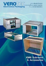
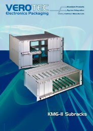
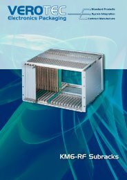
Subracks<br />
The KM6 subrack range; KM6-II, KM6-RF, KM6-EC and KM6-HD, is recognised<br />
worldwide as one of the leading products in its field having evolved around<br />
a number of international standards and in response to a number of trends.<br />
Principal among these trends are increased component densities, higher speed<br />
bus systems, greater connector contact counts, a greater range of operating<br />
environments, EMC and electrical safety regulations and, of course, economic<br />
pressures.<br />
The Subrack principle<br />
Why would you choose to use an extrusion based subrack ?<br />
In a word, accuracy. The need to provide a precise framework in which PCBs<br />
are supported and guided into connector positions is most efficiently achieved<br />
using accurate extrusion technology and hard-tooled end plate design. The<br />
subrack function now extends far beyond the pure support role and covers such<br />
areas as RFI protection, Shock and vibration protection, ESD protection and Fire<br />
enclosure safety to name but a few. Let’s examine a number of the functional<br />
aspects of the subrack and look at the alternative solutions available<br />
RFI protection<br />
This is achieved by the use of covers, EMC contact fingers and conductively<br />
finished mating parts. The Faraday cage achieved with subracks can give very<br />
high levels of signal attenuation across a wide band of frequencies. The nature<br />
of the construction also allows the user to define a balance between EMC and<br />
ventilation. Selective RFI protection is another option, with the use of plug in<br />
screened modules.<br />
There are a couple of alternatives, either the problem can be designed out at<br />
board level ( there is some doubt, however, that susceptibility problems can be<br />
designed out through tracking and layout changes), or the problem areas can<br />
be ‘canned’, but again there are some doubts regarding susceptibility.<br />
Shock and vibration<br />
This is achieved with the use of secure card guides (screwed in), two point<br />
extrusion to endplate fixing and additional mounting at the rear of the frame. It<br />
should be remembered that the effectiveness of the mounting is only as good<br />
as the rack/system into which the frame is mounted.<br />
There are only custom solutions for securely mounting PCBs without using a<br />
subrack and these are normally loosely based around the subrack principle.<br />
1 KM6 Subracks<br />
ESD protection<br />
This is achieved using grounding clips in the card guide system to discharge<br />
Electrostatic build up from the PCB either during insertion or during the course<br />
of normal operation in situ. Additional grounding at the front panel is now seen<br />
as good ESD practise and this is achieved either with the use of metal inserts or<br />
through the grounding pin in IEEE1101.10 Injector/Ejector mechanisms.<br />
Alternative methods of ESD are hard to define. Some claim that good<br />
production methods ie .operators fitted with discharge clips and product<br />
storage in anti-static packaging are helpful. Others claim sufficient discharge<br />
through an allocated pin(s) in the connector.<br />
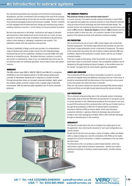
Extrusion based subrack<br />
RFI protected subrack<br />
Versatility<br />
The Subrack concept allows the user to configure the usable space to suit<br />
the application, thus removing the necessity to ‘tool’ each configuration as a<br />
custom solution.<br />
Divider kits for the front and rear allow a variety of heights, widths and depths<br />
within a single envelope size. Even the orientation of the PCBs can be readily<br />
changed from vertical to horizontal, or indeed a combination of the two within<br />
the same frame.<br />
The alternative to this is to produce a custom based solution, which may<br />
well produce a high tooling investment requirement. <strong>Verotec</strong> have made a<br />
significant investment in tooling to produce good quality, versatile subrack<br />
products.<br />
UK Tel: +44 (0)2380-246900 sales@verotec.co.uk<br />
USA Tel: 603.821.9921 sales@verotec.us<br />
1.03