Ch. 15 - (Part 2) Navigation - St. Louis Pilot Services
Ch. 15 - (Part 2) Navigation - St. Louis Pilot Services
Ch. 15 - (Part 2) Navigation - St. Louis Pilot Services
- No tags were found...

Create successful ePaper yourself
Turn your PDF publications into a flip-book with our unique Google optimized e-Paper software.
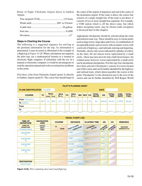
Airport which is directly to the east. <strong>Ch</strong>eckpoint 3 is WileyPost Airport, which the aircraft should fly directly over.<strong>Ch</strong>eckpoint 4 is a private, non-surfaced airport to the west ofthe course and can be further identified by the railroad trackand highway to the east of the course.The course and areas on either side of the planned routeshould be checked to determine if there is any type of airspacewith which the pilot should be concerned or which hasspecial operational requirements. For this trip, it should benoted that the course passes through a segment of the ClassC airspace surrounding Will Rogers World Airport where thefloor of the airspace is 2,500 feet mean sea level (MSL) andthe ceiling is 5,300 feet MSL (point B). Also, there is ClassD airspace from the surface to 3,800 feet MSL surroundingWiley Post Airport (point C) during the time the controltower is in operation.<strong>St</strong>udy the terrain and obstructions along the route. This isnecessary to determine the highest and lowest elevationsas well as the highest obstruction to be encountered so thatan appropriate altitude which conforms to 14 CFR part 91regulations can be selected. If the flight is to be flown at analtitude more than 3,000 feet above the terrain, conformanceto the cruising altitude appropriate to the direction of flightis required. <strong>Ch</strong>eck the route for particularly rugged terrain soit can be avoided. Areas where a takeoff or landing is madeshould be carefully checked for tall obstructions. Televisiontransmitting towers may extend to altitudes over 1,500 feetabove the surrounding terrain. It is essential that pilots beaware of their presence and location. For this trip, it shouldbe noted that the tallest obstruction is part of a series ofantennas with a height of 2,749 feet MSL (point D). Thehighest elevation should be located in the northeast quadrantand is 2,900 feet MSL (point E).Since the wind is no factor and it is desirable and within theaircraft’s capability to fly above the Class C and D airspaceto be encountered, an altitude of 5,500 feet MSL is chosen.This altitude also gives adequate clearance of all obstructionsas well as conforms to the 14 CFR part 91 requirement tofly at an altitude of odd thousand plus 500 feet when on amagnetic course between 0 and 179°.Next, the pilot should measure the total distance of thecourse as well as the distance between checkpoints. The totaldistance is 53 NM and the distance between checkpoints isas noted on the flight log in Figure <strong>15</strong>-26.After determining the distance, the true course should bemeasured. If using a plotter, follow the directions on theplotter. The true course is 031°. Once the true heading isestablished, the pilot can determine the compass heading.This is done by following the formula given earlier in thischapter. The formula is:TC ± WCA = TH ± V = MH ± D = CHThe WCA can be determined by using a manual or electronicflight computer. Using a wind of 360° at 10 knots, it isdetermined the WCA is 3° left. This is subtracted from theTC making the TH 28°. Next, the pilot should locate theisogonic line closest to the route of the flight to determinevariation. Figure <strong>15</strong>-25 shows the variation to be 6.30° E(rounded to 7° E), which means it should be subtracted fromthe TH, giving an MH of 21°. Next, add 2° to the MH forthe deviation correction. This gives the pilot the compassheading which is 23°.Now, the GS can be determined. This is done using a manualor electronic calculator. The GS is determined to be 106knots. Based on this information, the total trip time, as wellas time between checkpoints, and the fuel burned can bedetermined. These calculations can be done mathematicallyor by using a manual or electronic calculator.For this trip, the GS is 106 knots and the total time is 35minutes (30 minutes plus 5 minutes for climb) with a fuelburn of 4.7 gallons. Refer to the flight log in Figure <strong>15</strong>-26for the time between checkpoints.As the trip progresses, the pilot can note headings and timeand make adjustments in heading, GS, and time.Filing a VFR Flight PlanFiling a flight plan is not required by regulations; however, itis a good operating practice, since the information containedin the flight plan can be used in search and rescue in the eventof an emergency.Flight plans can be filed in the air by radio, but it is best tofile a flight plan by phone just before departing. After takeoff,contact the AFSS by radio and give them the takeoff time sothe flight plan can be activated.When a VFR flight plan is filed, it is held by the AFSS until1 hour after the proposed departure time and then canceledunless: the actual departure time is received; a revisedproposed departure time is received; or at the time of filing,the AFSS is informed that the proposed departure time ismet, but actual time cannot be given because of inadequatecommunication. The FSS specialist who accepts the flightplan does not inform the pilot of this procedure, however.<strong>15</strong>-20
Figure <strong>15</strong>-27 shows the flight plan form a pilot files with theAFSS. When filing a flight plan by telephone or radio, givethe information in the order of the numbered spaces. Thisenables the AFSS specialist to copy the information moreefficiently. Most of the fields are either self-explanatory ornon-applicable to the VFR flight plan (such as item 13).However, some fields may need explanation.• Item 3 is the aircraft type and special equipment. Anexample would be C-<strong>15</strong>0/X, which means the aircrafthas no transponder. A listing of special equipmentcodes is found in the Aeronautical Information Manual(AIM).• Item 6 is the proposed departure time in UTC(indicated by the “Z”).• Item 7 is the cruising altitude. Normally, “VFR” can beentered in this block, since the pilot chooses a cruisingaltitude to conform to FAA regulations.• Item 8 is the route of flight. If the flight is to be direct,enter the word “direct;” if not, enter the actual routeto be followed such as via certain towns or navigationaids.• Item 10 is the estimated time en route. In the sampleflight plan, 5 minutes was added to the total time toallow for the climb.• Item 12 is the fuel on board in hours and minutes. Thisis determined by dividing the total usable fuel aboardin gallons by the estimated rate of fuel consumptionin gallons.Remember, there is every advantage in filing a flight plan;but do not forget to close the flight plan on arrival. Do thisby telephone to avoid radio congestion.Radio <strong>Navigation</strong>Advances in navigational radio receivers installed in aircraft,the development of aeronautical charts which show the exactlocation of ground transmitting stations and their frequencies,along with refined flight deck instrumentation make itpossible for pilots to navigate with precision to almost anypoint desired. Although precision in navigation is obtainablethrough the proper use of this equipment, beginning pilotsshould use this equipment to supplement navigation by visualreference to the ground (pilotage). This method provides theXN123DB C<strong>15</strong>0/X 1<strong>15</strong> CHK, CHICKASHAAIRPORT 1400 5500<strong>Ch</strong>ickasha direct GuthrieGOK, Guthrie AirportGuthrie, OK35Jane Smith4 45Aero Air, Oklahoma City, OK (405) 555-41491Red/WhiteMcAlesterFigure <strong>15</strong>-27. Flight plan form.<strong>15</strong>-21
pilot with an effective safeguard against disorientation in theevent of radio malfunction.There are four radio navigation systems available for use forVFR navigation. These are:• VHF Omnidirectional Range (VOR)• Nondirectional Radio Beacon (NDB)• Long Range <strong>Navigation</strong> (LORAN-C)• Global Positioning System (GPS)Very High Frequency (VHF) OmnidirectionalRange (VOR)The VOR system is present in three slightly differentnavigation aids (NAVAIDs): VOR, VOR/DME, andVORTAC. By itself it is known as a VOR, and it providesmagnetic bearing information to and from the station. WhenDME is also installed with a VOR, the NAVAID is referredto as a VOR/DME. When military tactical air navigation(TACAN) equipment is installed with a VOR, the NAVAIDis known as a VORTAC. DME is always an integral part of aVORTAC. Regardless of the type of NAVAID utilized (VOR,VOR/DME or VORTAC), the VOR indicator behaves thesame. Unless otherwise noted, in this section, VOR, VOR/DME and VORTAC NAVAIDs are all referred to hereafteras VORs.The prefix “omni-” means all, and an omnidirectional rangeis a VHF radio transmitting ground station that projectsstraight line courses (radials) from the station in all directions.From a top view, it can be visualized as being similar tothe spokes from the hub of a wheel. The distance VORradials are projected depends upon the power output of thetransmitter.The course or radials projected from the station are referencedto magnetic north. Therefore, a radial is defined as a line ofmagnetic bearing extending outward from the VOR station.Radials are identified by numbers beginning with 001,which is 1° east of magnetic north, and progress in sequencethrough all the degrees of a circle until reaching 360. To aidin orientation, a compass rose reference to magnetic north issuperimposed on aeronautical charts at the station location.VOR ground stations transmit within a VHF frequency bandof 108.0–117.95 MHz. Because the equipment is VHF, thesignals transmitted are subject to line-of-sight restrictions.Therefore, its range varies in direct proportion to the altitudeof receiving equipment. Generally, the reception range ofthe signals at an altitude of 1,000 feet above ground level(AGL) is about 40 to 45 miles. This distance increases withaltitude. [Figure <strong>15</strong>-28]Only “A” Signal ReceivedVOR<strong>St</strong>ation“A”“A” and “B” SignalReceivedNeither “A” nor “B”Signal ReceivedOnly “B” Signal ReceivedVOR<strong>St</strong>ation“B”Figure <strong>15</strong>-28. VHF transmissions follow a line-of-sight course.VORs and VORTACs are classed according to operationaluse. There are three classes:• T (Terminal)• L (Low altitude)• H (High altitude)The normal useful range for the various classes is shown inthe following table:VOR/VORTAC NAVAIDSNormal Usable Altitudes and Radius DistancesDistanceClass Altitudes (Miles)T 12,000' and below 25L Below 18,000' 40H Below 14,500' 40HWithin the conterminous 48 statesonly, between 14,500 and 17,999' 100H 18,000'—FL 450 130H 60,000'—FL 450 100The useful range of certain facilities may be less than 50 miles.For further information concerning these restrictions, refer tothe Communication/NAVAID Remarks in the A/FD.<strong>15</strong>-22
The accuracy of course alignment of VOR radials isconsidered to be excellent. It is generally within plus orminus 1°. However, certain parts of the VOR receiverequipment deteriorate, and this affects its accuracy. This isparticularly true at great distances from the VOR station. Thebest assurance of maintaining an accurate VOR receiver isperiodic checks and calibrations. VOR accuracy checks arenot a regulatory requirement for VFR flight. However, toassure accuracy of the equipment, these checks should beaccomplished quite frequently and a complete calibrationeach year. The following means are provided for pilots tocheck VOR accuracy:• FAA VOR test facility (VOT)• Certified airborne checkpoints• Certified ground checkpoints located on airportsurfacesIf an aircraft has two VOR receivers installed, a dual VORreceiver check can be made. To accomplish the dual receivercheck, a pilot tunes both VOR receivers to the same VORground facility. The maximum permissible variation betweenthe two indicated bearings is 4 degrees. A list of the airborneand ground checkpoints is published in the A/FD.Basically, these checks consist of verifying that the VORradials the aircraft equipment receives are aligned with theradials the station transmits. There are not specific tolerancesin VOR checks required for VFR flight. But as a guide toassure acceptable accuracy, the required IFR tolerances canbe used—±4° for ground checks and ±6° for airborne checks.These checks can be performed by the pilot.The VOR transmitting station can be positively identifiedby its Morse code identification or by a recorded voiceidentification which states the name of the station followedby “VOR.” Many FSS transmit voice messages on the samefrequency that the VOR operates. Voice transmissions shouldnot be relied upon to identify stations, because many FSSremotely transmit over several omniranges, which havenames different from that of the transmitting FSS. If the VORis out of service for maintenance, the coded identification isremoved and not transmitted. This serves to alert pilots thatthis station should not be used for navigation. VOR receiversare designed with an alarm flag to indicate when signalstrength is inadequate to operate the navigational equipment.This happens if the aircraft is too far from the VOR or theaircraft is too low and, therefore, is out of the line of sightof the transmitting signals.Using the VORIn review, for VOR radio navigation, there are twocomponents required: ground transmitter and aircraftreceiving equipment. The ground transmitter is located at aspecific position on the ground and transmits on an assignedfrequency. The aircraft equipment includes a receiver witha tuning device and a VOR or omninavigation instrument.The navigation instrument could be a course deviationindicator (CDI), horizontal situation indicator (HSI), or aradio magnetic indicator (RMI). Each of these instrumentsindicates the course to the tuned VOR.Course Deviation Indicator (CDI)The CDI is found in most training aircraft. It consists of(1) omnibearing selector (OBS) sometimes referred to asthe course selector, (2) a CDI needle (Left-Right Needle),and (3) a TO/FROM indicator.The course selector is an azimuth dial that can be rotated toselect a desired radial or to determine the radial over whichthe aircraft is flying. In addition, the magnetic course “TO”or “FROM” the station can be determined.When the course selector is rotated, it moves the CDI orneedle to indicate the position of the radial relative to theaircraft. If the course selector is rotated until the deviationneedle is centered, the radial (magnetic course “FROM” thestation) or its reciprocal (magnetic course “TO” the station)can be determined. The course deviation needle also movesto the right or left if the aircraft is flown or drifting awayfrom the radial which is set in the course selector.By centering the needle, the course selector indicates eitherthe course “FROM” the station or the course “TO” the station.If the flag displays a “TO,” the course shown on the courseselector must be flown to the station. [Figure <strong>15</strong>-29] If30W24OBSCourse index33CDI needleApproximately 2 degreesin the VOR mode21OBS knobFigure <strong>15</strong>-29. VOR indicator.NSNAV3Unreliable signal flagTO<strong>15</strong>6ETO/FROM indicator12<strong>15</strong>-23
24“FROM” is displayed and the course shown is followed, theaircraft is flown away from the station.Horizontal Situation IndicatorThe HSI is a direction indicator that uses the outputfrom a flux valve to drive the compass card. The HSI[Figure <strong>15</strong>-30] combines the magnetic compass withnavigation signals and a glideslope. The HSI gives the pilotan indication of the location of the aircraft with relationshipto the chosen course or radial.In Figure <strong>15</strong>-30, the aircraft magnetic heading displayedon the compass card under the lubber line is 184°. Thecourse select pointer shown is set to 295°; the tail of thepointer indicates the reciprocal, 1<strong>15</strong>°. The course deviationbar operates with a VOR/Localizer (VOR/LOC) or GPSnavigation receiver to indicate left or right deviations fromthe course selected with the course select pointer; operatingin the same manner, the angular movement of a conventionalVOR/LOC needle indicates deviation from course.The desired course is selected by rotating the course selectpointer, in relation to the compass card, by means of thecourse select knob. The HSI has a fixed aircraft symboland the course deviation bar displays the aircraft’s positionrelative to the selected course. The TO/FROM indicator is atriangular pointer. When the indicator points to the head ofthe course select pointer, the arrow shows the course selected.If properly intercepted and flown, the course will take theaircraft to the chosen facility. When the indicator points to thetail of the course, the arrow shows that the course selected, ifproperly intercepted and flown, will take the aircraft directlyaway from the chosen facility.When the NAV warning flag appears it indicates no reliablesignal is being received. The appearance of the HDG flagindicates the compass card is not functioning properly.To/From indicatorCompass cardNAV warning flagGlideslope deviation scaleCourse deviation scaleCompass warning flagLubber lineThe glideslope pointer indicates the relation of the aircraft tothe glideslope. When the pointer is below the center position,the aircraft is above the glideslope and an increased rateof descent is required. In some installations, the azimuthcard is a remote indicating compass; however, in others theheading must be checked occasionally against the magneticcompass and reset.GSI2I5NAVDC2IHDG24GSRadio Magnetic Indicator (RMI)The RMI [Figure <strong>15</strong>-31] is a navigational aid providingaircraft magnetic or directional gyro heading and very highfrequency omnidirectional range (VOR), GPS, and automaticdirection finder (ADF) bearing information. Remote indicating633330HDG<strong>15</strong>S2112WCourse select knobSymbolic aircraftCourse deviation barADFE630ADFHeading select bugCourse select pointer3N33Dual glideslope pointersHeading select knobNAVNAVFigure <strong>15</strong>-30. Horizontal situation indicator.Figure <strong>15</strong>-31. Radio magnetic indicator.<strong>15</strong>-24
63030612compasses were developed to compensate for errors in andlimitations of older types of heading indicators.73033N3333The remote compass transmitter is a separate unit usuallymounted in a wingtip to eliminate the possibility of magneticinterference. The RMI consists of a compass card, a headingindex, two bearing pointers, and pointer function switches.The two pointers are driven by any two combinations of aGPS, an ADF, and/or a VOR. The pilot has the ability toselect the navigation aid to be indicated. The pointer indicatescourse to selected NAVAID or waypoint. In Figure <strong>15</strong>-31the green pointer is indicating the station tuned on the ADF.The yellow pointer is indicating the course to a VOR ofGPS waypoint. Note that there is no requirement for a pilotto select course with the RMI, but only the NAVAID is tobe indicated.W2430OBS30243024212I2I333333SN3I5I5<strong>15</strong>363FROMI26I2612E627W24OBS21018S6FROM<strong>15</strong>12E242II533I2WOBS3330N2424332I21866FROMI2SI5E<strong>15</strong>N1. Viewposi2. MovreseturnTracking With VORThe following describes a step-by-step procedure to use whentracking to and from a VOR station using a CDI. Figure <strong>15</strong>-32illustrates the procedure.W2430OBS2133SNTO<strong>15</strong>3612E5First, tune the VOR receiver to the frequency of the selectedVOR station. For example, 1<strong>15</strong>.0 to receive Bravo VOR. Next,check the identifiers to verify that the desired VOR is beingreceived. As soon as the VOR is properly tuned, the coursedeviation needle deflects either left or right. Then, rotate theazimuth dial to the course selector until the course deviationneedle centers and the TO-FROM indicator indicates “TO.”If the needle centers with a “FROM” indication, the azimuthshould be rotated 180° because, in this case, it is desired tofly “TO” the station. Now, turn the aircraft to the headingindicated on the VOR azimuth dial or course selector, 350°in this example.W24W2430OBS30OBS212133303333SSNN3TO<strong>15</strong>TO<strong>15</strong>633612612EE30243024332I332I3I53I56I26I243WINDI2If a heading of 350° is maintained with a wind from the rightas shown, the aircraft drifts to the left of the intended track.As the aircraft drifts off course, the VOR course deviationneedle gradually moves to the right of center or indicates thedirection of the desired radial or track.W2430OBS2421332ISNTO<strong>15</strong>I53612E2BRAVOBRA 1<strong>15</strong>.0To return to the desired radial, the aircraft heading must bealtered to the right. As the aircraft returns to the desired track,the deviation needle slowly returns to center. When centered,the aircraft is on the desired radial and a left turn must bemade toward, but not to the original heading of 350° becausea wind drift correction must be established. The amount ofcorrection depends upon the strength of the wind. If the windvelocity is unknown, a trial-and-error method can be usedto find the correct heading. Assume, for this example, a 10°correction for a heading of 360° is maintained.W2430OBS2133SNTO<strong>15</strong>3612E24302I33Figure <strong>15</strong>-32. Tracking a radial in a crosswind.I536I21<strong>15</strong>-25
While maintaining a heading of 360°, assume that the coursedeviation begins to move to the left. This means that the windcorrection of 10° is too great and the aircraft is flying to theright of course. A slight turn to the left should be made topermit the aircraft to return to the desired radial.When the deviation needle centers, a small wind driftcorrection of 5° or a heading correction of 355° should beflown. If this correction is adequate, the aircraft remainson the radial. If not, small variations in heading should bemade to keep the needle centered, and consequently keep theaircraft on the radial.As the VOR station is passed, the course deviation needlefluctuates, then settles down, and the “TO” indicationchanges to “FROM.” If the aircraft passes to one side of thestation, the needle deflects in the direction of the station asthe indicator changes to “FROM.”Generally, the same techniques apply when trackingoutbound as those used for tracking inbound. If the intent isto fly over the station and track outbound on the reciprocal ofthe inbound radial, the course selector should not be changed.Corrections are made in the same manner to keep the needlecentered. The only difference is that the omnidirectionalrange indicator indicates “FROM.”If tracking outbound on a course other than the reciprocal ofthe inbound radial, this new course or radial must be set inthe course selector and a turn made to intercept this course.After this course is reached, tracking procedures are the sameas previously discussed.Tips on Using the VOR• Positively identify the station by its code or voiceidentification.• Keep in mind that VOR signals are “line-of-sight.” Aweak signal or no signal at all is received if the aircraftis too low or too far from the station.• When navigating to a station, determine the inboundradial and use this radial. Fly a heading that willmaintain the course. If the aircraft drifts, fly a headingto re-intercept the course then apply a correction tocompensate for wind drift.• If minor needle fluctuations occur, avoid changingheadings immediately. Wait momentarily to see if theneedle recenters; if it does not, then correct.• When flying “TO” a station, always fly the selectedcourse with a “TO” indication. When flying “FROM” astation, always fly the selected course with a “FROM”indication. If this is not done, the action of the coursedeviation needle is reversed. To further explain thisreverse action, if the aircraft is flown toward a stationwith a “FROM” indication or away from a stationwith a “TO” indication, the course deviation needleindicates in an direction opposite to that which itshould indicate. For example, if the aircraft drifts tothe right of a radial being flown, the needle moves tothe right or points away from the radial. If the aircraftdrifts to the left of the radial being flown, the needlemoves left or in the direction opposite to the radial.• When navigating using the VOR it is important to flyheadings that maintain or re-intercept the course. Justturning toward the needle will cause overshootingthe radial and flying an S turn to the left and right ofcourse.Time and Distance <strong>Ch</strong>eck From a <strong>St</strong>ationTo compute time and distance from a station, first turn theaircraft to place the bearing pointer on the nearest 90° index.Note time and maintain heading. When the bearing pointerhas moved 10°, note the elapsed time in seconds and applythe formulas in the following example to determine time anddistance. [Figure <strong>15</strong>-33]Time-Distance <strong>Ch</strong>eck ExampleTime in seconds between bearings= Minutes to stationDegrees of bearing changeFor example, if 2 minutes (120 seconds) is required to fly abearing change of 10 degrees, the aircraft is—120= 12 minutes to the station10Figure <strong>15</strong>-33. Time-distance check example.The time from station may also be calculated by using a shortmethod based on the above formula, if a 10° bearing changeis flown. If the elapsed time for the bearing change is notedin seconds and a 10° bearing change is made, the time fromthe station in minutes is determined by counting off onedecimal point. Thus, if 75 seconds are required to fly a 10°bearing change, the aircraft is 7.5 minutes from the station.When the bearing pointer is moving rapidly or when severalcorrections are required to place the pointer on the wingtipposition, the aircraft is at station passage.The distance from the station is computed by multiplying TASor GS (in miles per minute) by the previously determined timein minutes. For example, if the aircraft is 7.5 minutes fromstation, flying at a TAS of 120 knots or 2 NM per minute, thedistance from station is <strong>15</strong> NM (7.5 x 2 = <strong>15</strong>).<strong>15</strong>-26
The preceding are methods of computing approximate timeand distance. The accuracy of time and distance checks isgoverned by existing wind, degree of bearing change, andaccuracy of timing. The number of variables involved causesthe result to be only an approximation. However, by flying anaccurate heading and checking the time and bearing closely,the pilot can make a reasonable estimate of time and distancefrom the station.Course InterceptCourse interceptions are performed in most phases ofinstrument navigation. The equipment used varies, but anintercept heading must be flown that results in an angle orrate of intercept sufficient to solve a particular problem.Rate of InterceptRate of intercept, seen by the aviator as bearing pointer orHSI movement, is a result of the following factors:• The angle at which the aircraft is flown toward adesired course (angle of intercept)• True airspeed and wind (GS)• Distance from the stationAngle of InterceptThe angle of intercept is the angle between the heading of theaircraft (intercept heading) and desired course. Controllingthis angle by selection/adjustment of the intercept headingis the easiest and most effective way to control courseinterceptions. Angle of intercept must be greater than thedegrees from course, but should not exceed 90°. Within thislimit, adjust to achieve the most desirable rate of intercept.When selecting an intercept heading, the key factor is therelationship between distance from the station and degreesfrom the course. Each degree, or radial, is 1 NM wide ata distance of 60 NM from the station. Width increases ordecreases in proportion to the 60 NM distance. For example,1 degree is 2 NM wide at 120 NM—and ½ NM wide at 30NM. For a given GS and angle of intercept, the resultant rateof intercept varies according to the distance from the station.When selecting an intercept heading to form an angle ofintercept, consider the following factors:• Degrees from course• Distance from the station• True airspeed and wind (GS)Distance Measuring Equipment (DME)Distance measuring equipment (DME) consists of an ultrahigh frequency (UHF) navigational aid with VOR/DMEs andVORTACs. It measures, in NM, the slant range distance ofan aircraft from a VOR/DME or VORTAC (both hereafterreferred to as a VORTAC). Although DME equipment is verypopular, not all aircraft are DME equipped.To utilize DME, the pilot should select, tune, and identifya VORTAC, as previously described. The DME receiver,utilizing what is called a “paired frequency” concept,automatically selects and tunes the UHF DME frequencyassociated with the VHF VORTAC frequency selected bythe pilot. This process is entirely transparent to the pilot.After a brief pause, the DME display shows the slant rangedistance to or from the VORTAC. Slant range distance is thedirect distance between the aircraft and the VORTAC, andis therefore affected by aircraft altitude. (<strong>St</strong>ation passagedirectly over a VORTAC from an altitude of 6,076 feet aboveground level (AGL) would show approximately 1.0 NM onthe DME.) DME is a very useful adjunct to VOR navigation.A VOR radial alone merely gives line of position information.With DME, a pilot may precisely locate the aircraft on thatline (radial).Most DME receivers also provide GS and time-to-stationmodes of operation. The GS is displayed in knots (NMPH).The time-to-station mode displays the minutes remaining toVORTAC station passage, predicated upon the present GS.GS and time-to-station information is only accurate whentracking directly to or from a VORTAC. DME receiverstypically need a minute or two of stabilized flight directly toor from a VORTAC before displaying accurate GS or timeto-stationinformation.Some DME installations have a hold feature that permitsa DME signal to be retained from one VORTAC while thecourse indicator displays course deviation information froman ILS or another VORTAC.VOR/DME RNAVArea navigation (RNAV) permits electronic course guidanceon any direct route between points established by the pilot.While RNAV is a generic term that applies to a variety ofnavigational aids, such as LORAN-C, GPS, and others, thissection deals with VOR/DME-based RNAV. VOR/DMERNAV is not a separate ground-based NAVAID, but amethod of navigation using VOR/DME and VORTACsignals specially processed by the aircraft’s RNAV computer.[Figure <strong>15</strong>-34]NOTE: In this section, the term “VORTAC” also includesVOR/DME NAVAIDs.In its simplest form, VOR/DME RNAV allows the pilot toelectronically move VORTACs around to more convenientlocations. Once electronically relocated, they are referredto as waypoints. These waypoints are described as a<strong>15</strong>-27
Area <strong>Navigation</strong> Direct RouteFigure <strong>15</strong>-34. Flying an RNAV course.combination of a selected radial and distance within theservice volume of the VORTAC to be used. These waypointsallow a straight course to be flown between almost anyorigin and destination, without regard to the orientation ofVORTACs or the existence of airways.While the capabilities and methods of operation of VOR/DME RNAV units differ, there are basic principles ofoperation that are common to all. <strong>Pilot</strong>s are urged to studythe manufacturer’s operating guide and receive instructionprior to the use of VOR/DME RNAV or any unfamiliarnavigational system. Operational information and limitationsshould also be sought from placards and the supplementsection of the AFM/POH.VOR/DME-based RNAV units operate in at least threemodes: VOR, en route, and approach. A fourth mode, VORParallel, may also be found on some models. The units needboth VOR and DME signals to operate in any RNAV mode.If the NAVAID selected is a VOR without DME, RNAVmode will not function.In the VOR (or non-RNAV) mode, the unit simply functionsas a VOR receiver with DME capability. [Figure <strong>15</strong>-35] Theunit’s display on the VOR indicator is conventional in allrespects. For operation on established airways or any otherordinary VOR navigation, the VOR mode is used.OFFSET3 3RNABEARING LOAD DISTANCE4 43 3 4 8 8 2 7 9Figure <strong>15</strong>-35. RNAV controls.12 12EN ROUTETo utilize the unit’s RNAV capability, the pilot selects andestablishes a waypoint or a series of waypoints to definea course. To operate in any RNAV mode, the unit needsboth radial and distance signals; therefore, a VORTAC (orVOR/DME) needs to be selected as a NAVAID. To establisha waypoint, a point somewhere within the service range ofa VORTAC is defined on the basis of radial and distance.Once the waypoint is entered into the unit and the RNAV enroute mode is selected, the CDI displays course guidance tothe waypoint, not the original VORTAC. DME also displaysdistance to the waypoint. Many units have the capability tostore several waypoints, allowing them to be programmedprior to flight, if desired, and called up in flight.RNAV waypoints are entered into the unit in magneticbearings (radials) of degrees and tenths (i.e., 275.5°) anddistances in NM and tenths (i.e., 25.2 NM). When plottingRNAV waypoints on an aeronautical chart, pilots find itdifficult to measure to that level of accuracy, and in practicalapplication, it is rarely necessary. A number of flight planningpublications publish airport coordinates and waypoints withthis precision and the unit accepts those figures. There is asubtle, but important difference in CDI operation and displayin the RNAV modes.In the RNAV modes, course deviation is displayed in termsof linear deviation. In the RNAV en route mode, maximumdeflection of the CDI typically represents 5 NM on either sideof the selected course, without regard to distance from thewaypoint. In the RNAV approach mode, maximum deflectionof the CDI typically represents 1¼ NM on either side of theselected course. There is no increase in CDI sensitivity as theaircraft approaches a waypoint in RNAV mode.The RNAV approach mode is used for instrument approaches.Its narrow scale width (¼ of the en route mode) permits veryprecise tracking to or from the selected waypoint. In visualflight rules (VFR) cross-country navigation, tracking a coursein the approach mode is not desirable because it requires agreat deal of attention and soon becomes tedious.A fourth, lesser-used mode on some units is the VOR Parallelmode. This permits the CDI to display linear (not angular)deviation as the aircraft tracks to and from VORTACs.It derives its name from permitting the pilot to offset (orparallel) a selected course or airway at a fixed distance ofthe pilot’s choosing, if desired. The VOR parallel modehas the same effect as placing a waypoint directly over anexisting VORTAC. Some pilots select the VOR parallelmode when utilizing the navigation (NAV) tracking functionof their autopilot for smoother course following near theVORTAC.Confusion is possible when navigating an aircraft with VOR/DME-based RNAV, and it is essential that the pilot become<strong>15</strong>-28
familiar with the equipment installed. It is not unknown forpilots to operate inadvertently in one of the RNAV modeswhen the operation was not intended by overlooking switchpositions or annunciators. The reverse has also occurred witha pilot neglecting to place the unit into one of the RNAVmodes by overlooking switch positions or annunciators.As always, the prudent pilot is not only familiar with theequipment used, but never places complete reliance in justone method of navigation when others are available forcross-check.Automatic Direction Finder (ADF)Many general aviation-type aircraft are equipped with ADFradio receiving equipment. To navigate using the ADF, thepilot tunes the receiving equipment to a ground station knownas a nondirectional radio beacon (NDB). The NDB stationsnormally operate in a low or medium frequency band of200 to 4<strong>15</strong> kHz. The frequencies are readily available onaeronautical charts or in the A/FD.All radio beacons except compass locators transmit acontinuous three-letter identification in code except duringvoice transmissions. A compass locator, which is associatedwith an instrument landing system, transmits a two-letteridentification.One of the disadvantages that should be considered whenusing low frequency (LF) for navigation is that low frequencysignals are very susceptible to electrical disturbances, such aslightning. These disturbances create excessive static, needledeviations, and signal fades. There may be interference fromdistant stations. <strong>Pilot</strong>s should know the conditions underwhich these disturbances can occur so they can be more alertto possible interference when using the ADF.Basically, the ADF aircraft equipment consists of a tuner,which is used to set the desired station frequency, and thenavigational display.The navigational display consists of a dial upon which theazimuth is printed, and a needle which rotates around the dialand points to the station to which the receiver is tuned.Some of the ADF dials can be rotated to align theazimuth with the aircraft heading; others are fixed with 0°representing the nose of the aircraft, and 180° representingthe tail. Only the fixed azimuth dial is discussed in thishandbook. [Figure <strong>15</strong>-36]<strong>St</strong>andard broadcast stations can also be used in conjunctionwith ADF. Positive identification of all radio stations isextremely important and this is particularly true when usingstandard broadcast stations for navigation.NDBs have one advantage over the VOR. This advantage isthat low or medium frequencies are not affected by line-ofsight.The signals follow the curvature of the Earth; therefore,if the aircraft is within the range of the station, the signalscan be received regardless of altitude.3330NN-S E-WW324216ES12<strong>15</strong>The following table gives the class of NDB stations, theirpower, and usable range:NONDIRECTIONAL RADIOBEACON (NDB)(Usable Radius Distances for All Altitudes)PowerDistanceClass (Watts) (Miles)Compass Locator Under 25 <strong>15</strong>MH Under 50 25H 50–1999 * 50HH 2000 or more 75* Service range of individual facilities may be less than 50miles.Figure <strong>15</strong>-36. ADF with fixed azimuth and magnetic compass.Figure <strong>15</strong>-37 illustrates terms that are used with the ADFand should be understood by the pilot.To determine the magnetic bearing “FROM” the station,180° is added to or subtracted from the magnetic bearing tothe station. This is the reciprocal bearing and is used whenplotting position fixes.<strong>15</strong>-29
N-S E-W2421WS12E36Magnetic North330°Magnetic bearing to stationMagnetic heading3330WN36E<strong>15</strong>12Relative bearing3033N2421S<strong>15</strong>Radio stationFigure <strong>15</strong>-37. ADF terms.330°Keep in mind that the needle of fixed azimuth points to thestation in relation to the nose of the aircraft. If the needle isdeflected 30° to the left for a relative bearing of 330°, thismeans that the station is located 30° left. If the aircraft isturned left 30°, the needle moves to the right 30° and indicatesa relative bearing of 0°, or the aircraft is pointing towardthe station. If the pilot continues flight toward the stationkeeping the needle on 0°, the procedure is called homing tothe station. If a crosswind exists, the ADF needle continues todrift away from zero. To keep the needle on zero, the aircraftmust be turned slightly resulting in a curved flightpath to thestation. Homing to the station is a common procedure, butresults in drifting downwind, thus lengthening the distanceto the station.Figure <strong>15</strong>-38. ADF tracking.3330W24N3216SE<strong>15</strong>12340° bearing to stationTracking to the station requires correcting for wind drift andresults in maintaining flight along a straight track or bearingto the station. When the wind drift correction is established,the ADF needle indicates the amount of correction to theright or left. For instance, if the magnetic bearing to thestation is 340°, a correction for a left crosswind wouldresult in a magnetic heading of 330°, and the ADF needlewould indicate 10° to the right or a relative bearing of 010°.[Figure <strong>15</strong>-38]When tracking away from the station, wind corrections aremade similar to tracking to the station, but the ADF needlepoints toward the tail of the aircraft or the 180° position onthe azimuth dial. Attempting to keep the ADF needle onthe 180° position during winds results in the aircraft flyinga curved flight leading further and further from the desiredtrack. To correct for wind when tracking outbound, correctionshould be made in the direction opposite of that in which theneedle is pointing.Although the ADF is not as popular as the VOR for radionavigation, with proper precautions and intelligent use, theADF can be a valuable aid to navigation.Loran-C <strong>Navigation</strong>Long range navigation, version C (LORAN-C) is anotherform of RNAV, but one that operates from chains oftransmitters broadcasting signals in the LF spectrum. WorldAeronautical <strong>Ch</strong>art (WAC), sectional charts, and VFRterminal area charts do not show the presence of LORAN-C transmitters. Selection of a transmitter chain is eithermade automatically by the unit, or manually by the pilotusing guidance information provided by the manufacturer.LORAN-C is a highly accurate, supplemental form ofnavigation typically installed as an adjunct to VOR andADF equipment. Databases of airports, NAVAIDs, and ATCfacilities are frequently features of LORAN-C receivers.<strong>15</strong>-30
LORAN-C is an outgrowth of the original LORAN-Adeveloped for navigation during World War II. The LORAN-Csystem is used extensively in maritime applications. Itexperienced a dramatic growth in popularity with pilots withthe advent of the small, panel-mounted LORAN-C receiversavailable at relatively low cost. These units are frequentlyvery sophisticated and capable, with a wide variety ofnavigational functions.With high levels of LORAN-C sophistication and capability,a certain complexity in operation is an unfortunate necessity.<strong>Pilot</strong>s are urged to read the operating handbooks and toconsult the supplements section of the AFM/POH prior toutilizing LORAN-C for navigation. Many units offer so manyfeatures that the manufacturers often publish two differentsets of instructions: (1) a brief operating guide and (2) indepthoperating manual.While coverage is not global, LORAN-C signals are suitablefor navigation in all of the conterminous United <strong>St</strong>ates, andparts of Canada and Alaska. Several foreign countries alsooperate their own LORAN-C systems. In the United <strong>St</strong>ates,the U.S. Coast Guard operates the LORAN-C system.LORAN-C system status is available from: USCG <strong>Navigation</strong>Center, Alexandria, Virginia at (703) 313-5900.LORAN-C absolute accuracy is excellent—position errorsare typically less than .25 NM. Repeatable accuracy, orthe ability to return to a waypoint previously visited, iseven better. While LORAN-C is a form of RNAV, it differssignificantly from VOR/DME-based RNAV. It operates in a90–110 kHz frequency range and is based upon measurementof the difference in arrival times of pulses of radio frequency(RF) energy emitted by a chain of transmitters hundreds ofmiles apart.Within any given chain of transmitters, there is a masterstation, and from three to five secondary stations. LORAN-C units must be able to receive at least a master and twosecondary stations to provide navigational information.Unlike VOR/DME-based RNAV, where the pilot must selectthe appropriate VOR/DME or VORTAC frequency, there isnot a frequency selection in LORAN-C. The most advancedunits automatically select the optimum chain for navigation.Other units rely upon the pilot to select the appropriate chainwith a manual entry.After the LORAN-C receiver has been turned on, the unitmust be initialized before it can be used for navigation. Whilethis can be accomplished in flight, it is preferable to performthis task, which can take several minutes, on the ground.The methods for initialization are as varied as the numberof different models of receivers. Some require pilot inputduring the process, such as verification or acknowledgmentof the information displayed.Most units contain databases of navigational information.Frequently, such databases contain not only airport andNAVAID locations, but also extensive airport, airspace, andATC information. While the unit can operate with an expireddatabase, the information should be current or verified to becorrect prior to use. The pilot can update some databases,while others require removal from the aircraft and the servicesof an avionics technician.VFR navigation with LORAN-C can be as simple as tellingthe unit where the pilot wishes to go. The course guidanceprovided is a great circle (shortest distance) route to thedestination. Older units may need a destination entered interms of latitude and longitude, but recent designs need onlythe identifier of the airport or NAVAID. The unit also permitsdatabase storage and retrieval of pilot defined waypoints.LORAN-C signals follow the curvature of the Earth and aregenerally usable hundreds of miles from their transmitters.The LORAN-C signal is subject to degradation from avariety of atmospheric disturbances. It is also susceptible tointerference from static electricity buildup on the airframeand electrically “noisy” airframe equipment. Flight inprecipitation or even dust clouds can cause occasionalinterference with navigational guidance from LORAN-Csignals. To minimize these effects, static wicks and bondingstraps should be installed and properly maintained.LORAN-C navigation information is presented to the pilot ina variety of ways. All units have self-contained displays, andsome elaborate units feature built-in moving map displays.Some installations can also drive an external moving mapdisplay, a conventional VOR indicator, or a horizontalsituation indicator (HSI). Course deviation information ispresented as a linear deviation from course—there is noincrease in tracking sensitivity as the aircraft approachesthe waypoint or destination. <strong>Pilot</strong>s must carefully observeplacards, selector switch positions, and annunciatorindications when utilizing LORAN-C because aircraftinstallations can vary widely. The pilot’s familiarity withunit operation through AFM/POH supplements and operatingguides cannot be overemphasized.LORAN-C Notices to Airmen (NOTAMs) should bereviewed prior to relying on LORAN-C for navigation.LORAN-C NOTAMs are issued to announce outages forspecific chains and transmitters. <strong>Pilot</strong>s may obtain LORAN-CNOTAMs from FSS briefers only upon request.<strong>15</strong>-31
The prudent pilot never relies solely on one means ofnavigation when others are available for backup and crosscheck.<strong>Pilot</strong>s should never become so dependent upon theextensive capabilities of LORAN-C that other methods ofnavigation are neglected.Global Positioning SystemThe GPS is a satellite-based radio navigation system. ItsRNAV guidance is worldwide in scope. There are no symbolsfor GPS on aeronautical charts as it is a space-based systemwith global coverage. Development of the system is underwayso that GPS is capable of providing the primary means ofelectronic navigation. Portable and yoke mounted units areproving to be very popular in addition to those permanentlyinstalled in the aircraft. Extensive navigation databases arecommon features in aircraft GPS receivers.The GPS is a satellite radio navigation and time disseminationsystem developed and operated by the U.S. Department ofDefense (DOD). Civilian interface and GPS system statusis available from the U.S. Coast Guard.It is not necessary to understand the technical aspects ofGPS operation to use it in VFR/instrument flight rules (IFR)navigation. It does differ significantly from conventional,ground-based electronic navigation, and awareness of thosedifferences is important. Awareness of equipment approvalsand limitations is critical to the safety of flight.The GPS navigation system broadcasts a signal that is usedby receivers to determine precise position anywhere in theworld. The receiver tracks multiple satellites and determinesa pseudorange measurement to determine the user location.A minimum of four satellites is necessary to establish anaccurate three-dimensional position. The Department ofDefense (DOD) is responsible for operating the GPS satelliteconstellation and monitors the GPS satellites to ensure properoperation.The status of a GPS satellite is broadcast as part of the datamessage transmitted by the satellite. GPS status informationis also available by means of the U.S. Coast Guard navigationinformation service at (703) 313-5907 or online at http://www.navcen.uscg.gov/. Additionally, satellite status isavailable through the Notice to Airmen (NOTAM) system.The GPS receiver verifies the integrity (usability) of thesignals received from the GPS constellation through receiverautonomous integrity monitoring (RAIM) to determine ifa satellite is providing corrupted information. At least onesatellite, in addition to those required for navigation, must bein view for the receiver to perform the RAIM function; thus,RAIM needs a minimum of five satellites in view, or foursatellites and a barometric altimeter (baro-aiding) to detect anintegrity anomaly. For receivers capable of doing so, RAIMneeds six satellites in view (or five satellites with baro-aiding)to isolate the corrupt satellite signal and remove it from thenavigation solution. Baro-aiding is a method of augmentingthe GPS integrity solution by using a nonsatellite inputsource. GPS derived altitude should not be relied upon todetermine aircraft altitude since the vertical error can be quitelarge and no integrity is provided. To ensure that baro-aidingis available, the current altimeter setting must be entered intothe receiver as described in the operating manual.RAIM messages vary somewhat between receivers; however,generally there are two types. One type indicates that thereare not enough satellites available to provide RAIM integritymonitoring and another type indicates that the RAIM integritymonitor has detected a potential error that exceeds the limitfor the current phase of flight. Without RAIM capability, thepilot has no assurance of the accuracy of the GPS position.Selective AvailabilitySelective Availability (SA) is a method by which the accuracyof GPS is intentionally degraded. This feature is designedto deny hostile use of precise GPS positioning data. SA wasdiscontinued on May 1, 2000, but many GPS receivers aredesigned to assume that SA is still active.The GPS constellation of 24 satellites is designed so that aminimum of five satellites are always observable by a useranywhere on earth. The receiver uses data from a minimum offour satellites above the mask angle (the lowest angle abovethe horizon at which a receiver can use a satellite).VFR Use of GPSGPS navigation has become a great asset to VFR pilots,providing increased navigation capability and enhancedsituational awareness, while reducing operating costs dueto greater ease in flying direct routes. While GPS has manybenefits to the VFR pilot, care must be exercised to ensurethat system capabilities are not exceeded.Types of receivers used for GPS navigation under VFR arevaried, from a full IFR installation being used to support aVFR flight, to a VFR only installation (in either a VFR or IFRcapable aircraft) to a hand-held receiver. The limitations ofeach type of receiver installation or use must be understoodby the pilot to avoid misusing navigation information. In allcases, VFR pilots should never rely solely on one systemof navigation. GPS navigation must be integrated withother forms of electronic navigation as well as pilotageand dead reckoning. Only through the integration of thesetechniques can the VFR pilot ensure accuracy in navigation.<strong>15</strong>-32
Some critical concerns in VFR use of GPS include RAIMcapability, database currency and antenna location.RAIM CapabilityMany VFR GPS receivers and all hand-held units have noRAIM alerting capability. Loss of the required number ofsatellites in view, or the detection of a position error, cannotbe displayed to the pilot by such receivers. In receiverswith no RAIM capability, no alert would be provided to thepilot that the navigation solution had deteriorated, and anundetected navigation error could occur. A systematic crosscheckwith other navigation techniques would identify thisfailure, and prevent a serious deviation.In many receivers, an up-datable database is used fornavigation fixes, airports, and instrument procedures.These databases must be maintained to the current updatefor IFR operation, but no such requirement exists for VFRuse. However, in many cases, the database drives a movingmap display which indicates Special Use Airspace and thevarious classes of airspace, in addition to other operationalinformation. Without a current database the moving mapdisplay may be outdated and offer erroneous information toVFR pilots wishing to fly around critical airspace areas, suchas a Restricted Area or a Class B airspace segment. Numerouspilots have ventured into airspace they were trying to avoidby using an outdated database. If there is not a current database in the receiver, disregard the moving map display whenmaking critical navigation decisions.In addition, waypoints are added, removed, relocated, or renamedas required to meet operational needs. When usingGPS to navigate relative to a named fix, a current databasemust be used to properly locate a named waypoint. Withoutthe update, it is the pilot’s responsibility to verify thewaypoint location referencing to an official current source,such as the A/FD, sectional chart, or en route chart.In many VFR installations of GPS receivers, antenna locationis more a matter of convenience than performance. In IFRinstallations, care is exercised to ensure that an adequateclear view is provided for the antenna to see satellites. If analternate location is used, some portion of the aircraft mayblock the view of the antenna, causing a greater opportunityto lose navigation signal.This is especially true in the case of hand-helds. The use ofhand-held receivers for VFR operations is a growing trend,especially among rental pilots. Typically, suction cups areused to place the GPS antennas on the inside of aircraftwindows. While this method has great utility, the antennalocation is limited by aircraft structure for optimal receptionof available satellites. Consequently, signal losses may occurin certain situations of aircraft-satellite geometry, causing aloss of navigation signal. These losses, coupled with a lackof RAIM capability, could present erroneous position andnavigation information with no warning to the pilot.While the use of a hand-held GPS for VFR operations is notlimited by regulation, modification of the aircraft, such asinstalling a panel- or yoke-mounted holder, is governed by 14CFR part 43. <strong>Pilot</strong>s should consult with a mechanic to ensurecompliance with the regulation and a safe installation.Tips for Using GPS for VFR OperationsAlways check to see if the unit has RAIM capability. If noRAIM capability exists, be suspicious of a GPS displayedposition when any disagreement exists with the positionderived from other radio navigation systems, pilotage, ordead reckoning.<strong>Ch</strong>eck the currency of the database, if any. If expired, updatethe database using the current revision. If an update of anexpired database is not possible, disregard any moving mapdisplay of airspace for critical navigation decisions. Be awarethat named waypoints may no longer exist or may havebeen relocated since the database expired. At a minimum,the waypoints planned to be used should be checked againsta current official source, such as the A/FD, or a SectionalAeronautical <strong>Ch</strong>art.While a hand-held GPS receiver can provide excellentnavigation capability to VFR pilots, be prepared forintermittent loss of navigation signal, possibly with no RAIMwarning to the pilot. If mounting the receiver in the aircraft,be sure to comply with 14 CFR part 43.Plan flights carefully before taking off. If navigating to userdefinedwaypoints, enter them before flight, not on the fly.Verify the planned flight against a current source, such as acurrent sectional chart. There have been cases in which onepilot used waypoints created by another pilot that were notwhere the pilot flying was expecting. This generally resultedin a navigation error. Minimize head-down time in the aircraftand keep a sharp lookout for traffic, terrain, and obstacles.Just a few minutes of preparation and planning on the groundmakes a great difference in the air.Another way to minimize head-down time is to become veryfamiliar with the receiver’s operation. Most receivers are notintuitive. The pilot must take the time to learn the variouskeystrokes, knob functions, and displays that are used inthe operation of the receiver. Some manufacturers providecomputer-based tutorials or simulations of their receivers.Take the time to learn about the particular unit before usingit in flight.<strong>15</strong>-33
In summary, be careful not to rely on GPS to solve all VFRnavigational problems. Unless an IFR receiver is installed inaccordance with IFR requirements, no standard of accuracyor integrity has been assured. While the practicality ofGPS is compelling, the fact remains that only the pilot cannavigate the aircraft, and GPS is just one of the pilot’s toolsto do the job.VFR WaypointsVFR waypoints provide VFR pilots with a supplementarytool to assist with position awareness while navigatingvisually in aircraft equipped with area navigation receivers.VFR waypoints should be used as a tool to supplement currentnavigation procedures. The uses of VFR waypoints includeproviding navigational aids for pilots unfamiliar with an area,waypoint definition of existing reporting points, enhancednavigation in and around Class B and Class C airspace, andenhanced navigation around Special Use Airspace. VFRpilots should rely on appropriate and current aeronauticalcharts published specifically for visual navigation. Ifoperating in a terminal area, pilots should take advantage ofthe Terminal Area <strong>Ch</strong>art available for that area, if published.The use of VFR waypoints does not relieve the pilot of anyresponsibility to comply with the operational requirementsof 14 CFR part 91.VFR waypoint names (for computer entry and flight plans)consist of five letters beginning with the letters “VP”and are retrievable from navigation databases. The VFRwaypoint names are not intended to be pronounceable,and they are not for use in ATC communications. On VFRcharts, a stand-alone VFR waypoint is portrayed using thesame four-point star symbol used for IFR waypoints. VFRwaypoint collocated with a visual checkpoint on the chart isidentified by a small magenta flag symbol. A VFR waypointcollocated with a visual checkpoint is pronounceable basedon the name of the visual checkpoint and may be used forATC communications. Each VFR waypoint name appears inparentheses adjacent to the geographic location on the chart.Latitude/longitude data for all established VFR waypointsmay be found in the appropriate regional A/FD.When filing VFR flight plans, use the five-letter identifier asa waypoint in the route of flight section if there is an intendedcourse change at that point or if used to describe the plannedroute of flight. This VFR filing would be similar to VOR usein a route of flight. <strong>Pilot</strong>s must use the VFR waypoints onlywhen operating under VFR conditions.Any VFR waypoints intended for use during a flight shouldbe loaded into the receiver while on the ground and prior todeparture. Once airborne, pilots should avoid programmingroutes or VFR waypoint chains into their receivers.<strong>Pilot</strong>s should be especially vigilant for other traffic whileoperating near VFR waypoints. The same effort to seeand avoid other aircraft near VFR waypoints is necessary,as is the case when operating near VORs and NDBs. Infact, the increased accuracy of navigation through the useof GPS demands even greater vigilance, as off-coursedeviations among different pilots and receivers is less.When operating near a VFR waypoint, use whatever ATCservices are available, even if outside a class of airspacewhere communications are required. Regardless of the classof airspace, monitor the available ATC frequency closely forinformation on other aircraft operating in the vicinity. It isalso a good idea to turn on landing light(s) when operatingnear a VFR waypoint to make the aircraft more conspicuousto other pilots, especially when visibility is reduced.Lost ProceduresGetting lost in an aircraft is a potentially dangerous situationespecially when low on fuel. If a pilot becomes lost, thereare some good common sense procedures to follow. If atown or city cannot be seen, the first thing to do is climb,being mindful of traffic and weather conditions. An increasein altitude increases radio and navigation reception range,and also increases radar coverage. If flying near a town orcity, it might be possible to read the name of the town on awater tower.If the aircraft has a navigational radio, such as a VOR or ADFreceiver, it can be possible to determine position by plottingan azimuth from two or more navigational facilities. If GPSis installed, or a pilot has a portable aviation GPS on board,it can be used to determine the position and the location ofthe nearest airport.Communicate with any available facility using frequenciesshown on the sectional chart. If contact is made with acontroller, radar vectors may be offered. Other facilities mayoffer direction finding (DF) assistance. To use this procedure,the controller requests the pilot to hold down the transmitbutton for a few seconds and then release it. The controllermay ask the pilot to change directions a few times and repeatthe transmit procedure. This gives the controller enoughinformation to plot the aircraft position and then give vectorsto a suitable landing site. If the situation becomes threatening,transmit the situation on the emergency frequency 121.5 MHzand set the transponder to 7700. Most facilities, and evenairliners, monitor the emergency frequency.Flight DiversionThere probably comes a time when a pilot is not able tomake it to the planned destination. This can be the result ofunpredicted weather conditions, a system malfunction, or<strong>15</strong>-34
poor preflight planning. In any case, the pilot needs to beable to safely and efficiently divert to an alternate destination.Before any cross-country flight, check the charts for airportsor suitable landing areas along or near the route of flight.Also, check for navigational aids that can be used during adiversion.Computing course, time, speed, and distance information inflight requires the same computations used during preflightplanning. However, because of the limited flight deck space,and because attention must be divided between flying theaircraft, making calculations, and scanning for other aircraft,take advantage of all possible shortcuts and rule-of-thumbcomputations.When in flight, it is rarely practical to actually plot a courseon a sectional chart and mark checkpoints and distances.Furthermore, because an alternate airport is usually notvery far from your original course, actual plotting is seldomnecessary.A course to an alternate can be measured accurately with aprotractor or plotter, but can also be measured with reasonableaccuracy using a straightedge and the compass rose depictedaround VOR stations. This approximation can be made on thebasis of a radial from a nearby VOR or an airway that closelyparallels the course to your alternate. However, rememberthat the magnetic heading associated with a VOR radialor printed airway is outbound from the station. To find thecourse TO the station, it may be necessary to determine thereciprocal of that heading. It is typically easier to navigateto an alternate airport that has a VOR or NDB facility onthe field.After selecting the most appropriate alternate, approximatethe magnetic course to the alternate using a compass roseor airway on the sectional chart. If time permits, try to startthe diversion over a prominent ground feature. However,in an emergency, divert promptly toward your alternate.Attempting to complete all plotting, measuring, andcomputations involved before diverting to the alternate mayonly aggravate an actual emergency.Once established on course, note the time, and then use thewinds aloft nearest to your diversion point to calculate aheading and GS. Once a GS has been calculated, determinea new arrival time and fuel consumption. Give priority toflying the aircraft while dividing attention between navigationand planning. When determining an altitude to use whilediverting, consider cloud heights, winds, terrain, and radioreception.<strong>Ch</strong>apter SummaryThis chapter has discussed the fundamentals of VFRnavigation. Beginning with an introduction to the charts thatcan be used for navigation to the more technically advancedconcept of GPS, there is one aspect of navigation that remainsthe same. The pilot is responsible for proper planning and theexecution of that planning to ensure a safe flight.<strong>15</strong>-35
<strong>15</strong>-36