The Air Traffic Control System - St. Louis Pilot Services
The Air Traffic Control System - St. Louis Pilot Services
The Air Traffic Control System - St. Louis Pilot Services

Create successful ePaper yourself
Turn your PDF publications into a flip-book with our unique Google optimized e-Paper software.
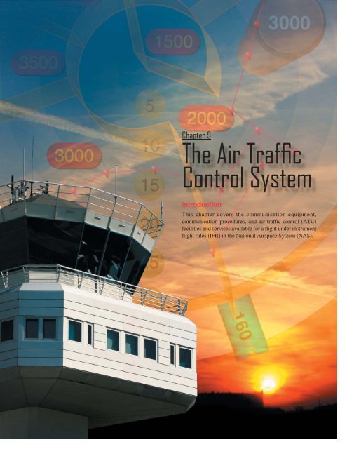
Chapter 9<strong>The</strong> <strong>Air</strong> <strong>Traffic</strong><strong>Control</strong> <strong>System</strong>IntroductionThis chapter covers the communication equipment,communication procedures, and air traffic control (ATC)facilities and services available for a flight under instrumentflight rules (IFR) in the National <strong>Air</strong>space <strong>System</strong> (NAS).9-1
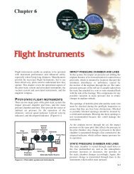
Communication EquipmentNavigation/Communication (NAV/COM)EquipmentCivilian pilots communicate with ATC on frequencies inthe very high frequency (VHF) range between 118.000 and136.975 MHz. To derive full benefit from the ATC system,radios capable of 25 kHz spacing are required (e.g., 134.500,134.575, 134.600). If ATC assigns a frequency that cannotbe selected, ask for an alternative frequency.Figure 9-1 illustrates a typical radio panel installation,consisting of a communications transceiver on the left and anavigational receiver on the right. Many radios allow the pilotto have one or more frequencies stored in memory and onefrequency active for transmitting and receiving (called simplexoperation). It is possible to communicate with some automatedflight service stations (AFSS) by transmitting on 122.1 MHz(selected on the communication radio) and receiving on aVHF omnidirectional range (VOR) frequency (selected onthe navigation radio). This is called duplex operation.An audio panel allows a pilot to adjust the volume of theselected receiver(s) and to select the desired transmitter.[Figure 9-2] <strong>The</strong> audio panel has two positions for receiverselection, cabin speaker, and headphone (some units mighthave a center “off” position). Use of a hand-held microphoneand the cabin speaker introduces the distraction of reachingfor and hanging up the microphone. A headset with a boommicrophone is recommended for clear communications. <strong>The</strong>microphone should be positioned close to the lips to reduceFigure 9-1. Typical NAV/COM Installation.Figure 9-2. Audio Panel.9-2
Figure 9-4. Combination GPS-Com Unit.select the appropriate communications frequency for thatlocation in the communications radio.Radar and TranspondersATC radars have a limited ability to display primary returns,which is energy reflected from an aircraft’s metallic structure.<strong>The</strong>ir ability to display secondary returns (transponder repliesto ground interrogation signals) makes possible the manyadvantages of automation.Figure 9-3. Boom Microphone, Headset, and Push-To-TalkSwitch.the possibility of ambient flight deck noise interfering withtransmissions to the controller. Headphones deliver thereceived signal directly to the ears; therefore, ambient noisedoes not interfere with the pilot’s ability to understand thetransmission. [Figure 9-3]Switching the transmitter selector between COM1 andCOM2 changes both transmitter and receiver frequencies.It is necessary only when a pilot wants to monitor onefrequency while transmitting on another. One example islistening to automatic terminal information service (ATIS)on one receiver while communicating with ATC on theother. Monitoring a navigation receiver to check for properidentification is another reason to use the switch panel.Most audio switch panels also include a marker beaconreceiver. All marker beacons transmit on 75 MHz, so thereis no frequency selector.Figure 9-4 illustrates an increasingly popular form ofNAV/COM radio; it contains a global positioning system(GPS) receiver and a communications transceiver. Using itsnavigational capability, this unit can determine when a flightcrosses an airspace boundary or fix and can automaticallyA transponder is a radar beacon transmitter/receiver installedin the instrument panel. ATC beacon transmitters send outinterrogation signals continuously as the radar antennarotates. When an interrogation is received by a transponder, acoded reply is sent to the ground station where it is displayedon the controller’s scope. A reply light on the transponderpanel flickers every time it receives and replies to a radarinterrogation. Transponder codes are assigned by ATC.When a controller asks a pilot to “ident” and the ident buttonis pushed, the return on the controller’s scope is intensified forprecise identification of a flight. When requested, briefly pushthe ident button to activate this feature. It is good practicefor pilots to verbally confirm that they have changed codesor pushed the ident button.Mode C (Altitude Reporting)Primary radar returns indicate only range and bearing fromthe radar antenna to the target; secondary radar returns candisplay altitude, Mode C, on the control scope if the aircraftis equipped with an encoding altimeter or blind encoder. Ineither case, when the transponder’s function switch is in theALT position the aircraft’s pressure altitude is sent to thecontroller. Adjusting the altimeter’s Kollsman window hasno effect on the altitude read by the controller.Transponders, when installed, must be ON at all times whenoperating in controlled airspace; altitude reporting is requiredby regulation in Class B and Class C airspace and inside a30-mile circle surrounding the primary airport in Class Bairspace. Altitude reporting should also be ON at all times.9-3
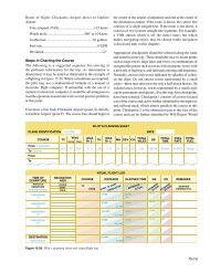
Communication ProceduresClarity in communication is essential for a safe instrumentflight. This requires pilots and controllers to use terms thatare understood by both—the <strong>Pilot</strong>/<strong>Control</strong>ler Glossary in theAeronautical Information Manual (AIM) is the best source ofterms and definitions. <strong>The</strong> AIM is revised twice a year andnew definitions are added, so the glossary should be reviewedfrequently. Because clearances and instructions are comprisedlargely of letters and numbers, a phonetic pronunciation guidehas been developed for both. [Figure 9-5]ground communication outlets (GCOs), and by using duplextransmissions through navigational aids (NAVAIDs). <strong>The</strong>best source of information on frequency usage is the <strong>Air</strong>port/Facility Directory (A/FD) and the legend panel on sectionalcharts also contains contact information.ATCs must follow the guidance of the <strong>Air</strong> <strong>Traffic</strong> <strong>Control</strong>Manual when communicating with pilots. <strong>The</strong> manualpresents the controller with different situations and prescribesprecise terminology that must be used. This is advantageousfor pilots because once they have recognized a patternor format they can expect future controller transmissionsto follow that format. <strong>Control</strong>lers are faced with a widevariety of communication styles based on pilot experience,proficiency, and professionalism.<strong>Pilot</strong>s should study the examples in the AIM, listen toother pilots communicate, and apply the lessons learnedto their own communications with ATC. <strong>Pilot</strong>s should askfor clarification of a clearance or instruction. If necessary,use plain English to ensure understanding, and expect thecontroller to reply in the same way. A safe instrument flightis the result of cooperation between controller and pilot.Communication Facilities<strong>The</strong> controller’s primary responsibility is separation ofaircraft operating under IFR. This is accomplished with ATCfacilities which include the AFSS, airport traffic control tower(ATCT), terminal radar approach control (TRACON), andair route traffic control center (ARTCC).Automated Flight Service <strong>St</strong>ations (AFSS)A pilot’s first contact with ATC is usually through AFSS,either by radio or telephone. AFSSs provide pilot briefings,receive and process flight plans, relay ATC clearances,originate Notices to <strong>Air</strong>men (NOTAMs), and broadcastaviation weather. Some facilities provide En Route FlightAdvisory Service (EFAS), take weather observations,and advise United <strong>St</strong>ates Customs and Immigration ofinternational flights.Telephone contact with Flight Service can be obtainedby dialing 1-800-WX-BRIEF. This number can be usedanywhere in the United <strong>St</strong>ates and connects to the nearestAFSS based on the area code from which the call originates.<strong>The</strong>re are a variety of methods of making radio contact:direct transmission, remote communication outlets (RCOs),Figure 9-5. Phonetic Pronunciation Guide.9-4
<strong>The</strong> briefer sends a flight plan to the host computer atthe ARTCC (Center). After processing the flight plan,the computer will send flight strips to the tower, to theradar facility that will handle the departure route, and tothe Center controller whose sector the flight first enters.Figure 9-6 shows a typical strip. <strong>The</strong>se strips are deliveredapproximately 30 minutes prior to the proposed departuretime. <strong>St</strong>rips are delivered to en route facilities 30 minutesbefore the flight is expected to enter their airspace. If aflight plan is not opened, it will “time out” 2 hours after theproposed departure time.When departing an airport in Class G airspace, a pilot receivesan IFR clearance from the AFSS by radio or telephone. Itcontains either a clearance void time, in which case an aircraftmust be airborne prior to that time, or a release time. <strong>Pilot</strong>sshould not take-off prior to the release time. <strong>Pilot</strong>s can helpthe controller by stating how soon they expect to be airborne.If the void time is, for example, 10 minutes past the hour andan aircraft is airborne at exactly 10 minutes past the hour,the clearance is void—a pilot must take off prior to the voidtime. A specific void time may be requested when filing aflight plan.ATC TowersSeveral controllers in the tower cab are involved in handlingan instrument flight. Where there is a dedicated clearancedelivery position, that frequency is found in the A/FD andon the instrument approach chart for the departure airport.Where there is no clearance delivery position, the groundcontroller performs this function. At the busiest airports, pretaxiclearance is required; the frequency for pre-taxi clearancecan be found in the A/FD. Taxi clearance should be requestednot more than 10 minutes before proposed taxi time.It is recommended that pilots read their IFR clearance back tothe clearance delivery controller. Instrument clearances canbe overwhelming when attempting to copy them verbatim,but they follow a format that allows a pilot to be preparedwhen responding “Ready to copy.” <strong>The</strong> format is: clearancelimit (usually the destination airport); route, including anydeparture procedure; initial altitude; frequency (for departurecontrol); and transponder code. With the exception of thetransponder code, a pilot knows most of these items beforeengine start. One technique for clearance copying is writingC-R-A-F-T.Assume an IFR flight plan has been filed from Seattle,Washington to Sacramento, California via V-23 at 7,000feet. <strong>Traffic</strong> is taking off to the north from Seattle-Tacoma(Sea-Tac) airport and, by monitoring the clearance deliveryfrequency, a pilot can determine the departure procedurebeing assigned to southbound flights. <strong>The</strong> clearance limitis the destination airport, so write “SAC” after the letter C.Write “SEATTLE TWO – V23” after R for Route, becausedeparture control issued this departure to other flights. Write“7” after the A, the departure control frequency printed onthe approach charts for Sea-Tac after F, and leave the spaceafter the letter T blank—the transponder code is generated bycomputer and can seldom be determined in advance. <strong>The</strong>n,call clearance delivery and report “Ready to copy.”As the controller reads the clearance, check it against whatis already written down; if there is a change, draw a linethrough that item and write in the changed item. Chancesare the changes are minimal, and most of the clearance iscopied before keying the microphone. <strong>St</strong>ill, it is worthwhileto develop clearance shorthand to decrease the verbiage thatmust be copied (see Appendix 1).<strong>Pilot</strong>s are required to have either the text of a departureprocedure (DP) or a graphic representation (if one isavailable), and should review it before accepting a clearance.This is another reason to find out ahead of time which DP isin use. If the DP includes an altitude or a departure controlfrequency, those items are not included in the clearance.<strong>The</strong> last clearance received supersedes all previous clearances.For example, if the DP says “Climb and maintain 2,000 feet,expect higher in 6 miles,” but upon contacting the departurecontroller a new clearance is received: “Climb and maintain8,000 feet,” the 2,000 feet restriction has been canceled. Thisrule applies in both terminal and Center airspace.Figure 9-6. Flight <strong>St</strong>rip.9-5
assigned code. For this reason, the transponder should remainon standby until takeoff clearance has been received.<strong>The</strong> aircraft appears on the controller’s radar display as atarget with an associated data block that moves as the aircraftmoves through the airspace. <strong>The</strong> data block includes aircraftidentification, aircraft type, altitude, and airspeed.A TRACON controller uses <strong>Air</strong>port Surveillance Radar(ASR) to detect primary targets and Automated RadarTerminal <strong>System</strong>s (ARTS) to receive transponder signals; thetwo are combined on the controller’s scope. [Figure 9-9]At facilities with ASR-3 equipment, radar returns fromprecipitation are not displayed as varying levels of intensity,and controllers must rely on pilot reports and experienceto provide weather avoidance information. With ASR-9equipment, the controller can select up to six levels ofintensity. Light precipitation does not require avoidancetactics but precipitation levels of moderate, heavy orextreme should cause pilots to plan accordingly. Alongwith precipitation the pilot must additionally consider thetemperature, which if between -20° and +5° C will cause icingeven during light precipitation. <strong>The</strong> returns from higher levelsof intensity may obscure aircraft data blocks, and controllersmay select the higher levels only on pilot request. Whenuncertainty exists about the weather ahead, ask the controllerif the facility can display intensity levels—pilots of smallaircraft should avoid intensity levels 3 or higher.Tower En Route <strong>Control</strong> (TEC)At many locations, instrument flights can be conductedentirely in terminal airspace. <strong>The</strong>se TEC routes are generallyfor aircraft operating below 10,000 feet, and they can befound in the A/FD. <strong>Pilot</strong>s desiring to use TEC should includethat designation in the remarks section of the flight plan.<strong>Pilot</strong>s are not limited to the major airports at the city pairslisted in the A/FD. For example, a tower en route flight froman airport in New York (NYC) airspace could terminateat any airport within approximately 30 miles of BradleyInternational (BDL) airspace, such as Hartford (HFD).[Figure 9-10]A valuable service provided by the automated radarequipment at terminal radar facilities is the Minimum SafeAltitude Warnings (MSAW). This equipment predicts anaircraft’s position in 2 minutes based on present path offlight—the controller issues a safety alert if the projectedpath encounters terrain or an obstruction. An unusuallyrapid descent rate on a nonprecision approach can triggersuch an alert.<strong>Air</strong> Route <strong>Traffic</strong> <strong>Control</strong> Center (ARTCC)ARTCC facilities are responsible for maintaining separationbetween IFR flights in the en route structure. Center radars(<strong>Air</strong> Route Surveillance Radar (ARSR)) acquire and tracktransponder returns using the same basic technology asterminal radars. [Figure 9-11]Earlier Center radars display weather as an area of slashes(light precipitation) and Hs (moderate rainfall), as illustratedin Figure 9-12. Because the controller cannot detect higherlevels of precipitation, pilots should be wary of areas showingmoderate rainfall. Newer radar displays show weather asthree levels of blue. <strong>Control</strong>lers can select the level of weatherto be displayed. Weather displays of higher levels of intensitycan make it difficult for controllers to see aircraft data blocks,so pilots should not expect ATC to keep weather displayedcontinuously.Center airspace is divided into sectors in the same manneras terminal airspace; additionally, most Center airspace isdivided by altitudes into high and low sectors. Each sectorhas a dedicated team of controllers and a selection of radiofrequencies, because each Center has a network of remotetransmitter/receiver sites. All Center frequencies can be foundin the back of the A/FD in the format shown in Figure 9-13;they are also found on en route charts.Each ARTCC’s area of responsibility covers several states;when flying from the vicinity of one remote communicationsite toward another, expect to hear the same controller ondifferent frequencies.Center Approach/Departure <strong>Control</strong><strong>The</strong> majority of airports with instrument approaches do notlie within terminal radar airspace, and when operating toor from these airports pilots communicate directly with theCenter controller. Departing from a tower-controlled airport,the tower controller provides instructions for contacting theappropriate Center controller. When departing an airportwithout an operating control tower, the clearance includesinstructions such as “Upon entering controlled airspace,contact Houston Center on 126.5.” <strong>Pilot</strong>s are responsiblefor terrain clearance until reaching the controller’s MVA.Simply hearing “Radar contact” does not relieve a pilot ofthis responsibility.If obstacles in the departure path require a steeper-thanstandardclimb gradient (200 FPNM), then the controlleradvises the pilot. However, it is the pilot’s responsibility tocheck the departure airport listing in the A/FD to determine ifthere are trees or wires in the departure path. When in doubt,ask the controller for the required climb gradient.9-7
Figure 9-9. <strong>The</strong> top image is a display as seen by controllers in an <strong>Air</strong> Traffi c Facility. <strong>The</strong> one illustrated is an ARTS III (AutomatedRadar Terminal <strong>System</strong>). <strong>The</strong> display shown provides an explanation of the symbols in the graphic. <strong>The</strong> lower fi gure is an example ofthe Digital Bright Radar Indicator Tower Equipment (DBRITE) screen as seen by tower personnel. It provides tower controllers witha visual display of the airport surveillance radar, beacon signals, and data received from ARTS III. <strong>The</strong> display shown provides anexplanation of the symbols in the graphic.9-8
Figure 9-11. Center Radar Displays.Figure 9-12. A Center <strong>Control</strong>ler’s Scope.A common clearance in these situations is “When able,proceed direct to the Astoria VOR…” <strong>The</strong> words “when able”mean to proceed to the waypoint, intersection, or NAVAIDwhen the pilot is able to navigate directly to that point usingonboard available systems providing proper guidance, usablesignal, etc. If provided such guidance while flying VFR, thepilot remains responsible for terrain and obstacle clearance.Using the standard climb gradient, an aircraft is 2 milesfrom the departure end of the runway before it is safe toturn (400 feet above ground level (AGL)). When a Centercontroller issues a heading, a direct route, or says “directwhen able,” the controller becomes responsible for terrainand obstruction clearance.Another common Center clearance is “Leaving (altitude)fly (heading) or proceed direct when able.” This keeps theterrain/obstruction clearance responsibility in the flight deckuntil above the minimum IFR altitude. A controller cannotissue an IFR clearance until an aircraft is above the minimumIFR altitude unless it is able to climb in VFR conditions.On a Center controller’s scope, 1 NM is about 1/28 of an inch.When a Center controller is providing Approach/Departurecontrol services at an airport many miles from the radarantenna, estimating headings and distances is very difficult.<strong>Control</strong>lers providing vectors to final must set the range ontheir scopes to not more than 125 NM to provide the greatestpossible accuracy for intercept headings. Accordingly, atlocations more distant from a Center radar antenna, pilotsshould expect a minimum of vectoring.Figure 9-13. Center Symbology.9-10
stated in 14 CFR part 91, section 91.3 should an immediatedeviation from the assigned clearance be necessary and timedoes not permit approval by ATC.Generally, when weather disrupts the flow of air traffic,greater workload demands are placed on the controller.Requests for deviations from course and other servicesshould be made as far in advance as possible to better assurethe controller’s ability to approve these requests promptly.When requesting approval to detour around weather activity,include the following information to facilitate the request:1. <strong>The</strong> proposed point where detour commences;2. <strong>The</strong> proposed route and extent of detour (directionand distance);3. <strong>The</strong> point where original route will be resumed;4. Flight conditions (IMC or VMC);5. Whether the aircraft is equipped with functioningairborne radar; and6. Any further deviation that may become necessary.Approach <strong>Control</strong> FacilityAn approach control facility is a terminal ATC facilitythat provides approach control service in the terminal area.<strong>Services</strong> are provided for arriving and departing VFR andIFR aircraft and, on occasion, en route aircraft. In addition,for airports with parallel runways with ILS or LDAapproaches, the approach control facility provides monitoringof the approaches.Approach <strong>Control</strong> AdvancesPrecision Runway Monitor (PRM)Over the past few years, a new technology has been installedat airports that permits a decreased separation distancebetween parallel runways. <strong>The</strong> system is called a PrecisionRunway Monitor (PRM) and is comprised of high-updateradar, high-resolution ATC displays, and PRM-certifiedcontrollers. [Figure 9-14]To a large degree, the assistance that might be renderedby ATC depends upon the weather information availableto controllers. Due to the extremely transitory nature ofhazardous weather, the controller’s displayed precipitationinformation may be of limited value.Obtaining IFR clearance or approval to circumnavigatehazardous weather can often be accommodated more readilyin the en route areas away from terminals because thereis usually less congestion and, therefore, greater freedomof action. In terminal areas, the problem is more acutebecause of traffic density, ATC coordination requirements,complex departure and arrival routes, and adjacent airports.As a consequence, controllers are less likely to be able toaccommodate all requests for weather detours in a terminalarea. Nevertheless, pilots should not hesitate to advisecontrollers of any observed hazardous weather and shouldspecifically advise controllers if they desire circumnavigationof observed weather.<strong>Pilot</strong> reports (PIREPs) of flight conditions help define thenature and extent of weather conditions in a particular area.<strong>The</strong>se reports are disseminated by radio and electronic meansto other pilots. Provide PIREP information to ATC regardingpertinent flight conditions, such as:1. Turbulence;2. Visibility;3. Cloud tops and bases; and4. <strong>The</strong> presence of hazards such as ice, hail, andlightning.Figure 9-14. High Resolution ATC Displays Used in PRM.Precision Runway Monitor (PRM) Radar<strong>The</strong> PRM uses a Monopulse Secondary Surveillance Radar(MSSR) that employs electronically scanned antennas.Because the PRM has no scan rate restrictions, it is capableof providing a faster update rate (up to 0.5 second) overconventional systems, thereby providing better targetpresentation in terms of accuracy, resolution, and trackprediction. <strong>The</strong> system is designed to search, track, process,and display SSR-equipped aircraft within airspace of over30 miles in range and over 15,000 feet in elevation. Visualand audible alerts are generated to warn controllers to takecorrective actions.9-12
Figure 9-15. <strong>Air</strong>craft Management Using PRM. (Note the no transgression zone (NTZ) and how the aircraft are separated.)PRM BenefitsTypically, PRM is used with dual approaches with centerlinesseparated less than 4,300 feet but not less than 3,000 feet(under most conditions). [Figure 9-15] Separating the twofinal approach courses is a No Transgression Zone (NTZ)with surveillance of that zone provided by two controllers,one for each active approach. <strong>The</strong> system tracking softwareprovides PRM monitor controllers with aircraft identification,position, speed, projected position, as well as visual andaural alerts.<strong>Control</strong> Sequence<strong>The</strong> IFR system is flexible and accommodating if pilots dotheir homework, have as many frequencies as possible writtendown before they are needed, and have an alternate in mindif the flight cannot be completed as planned. <strong>Pilot</strong>s shouldfamiliarize themselves with all the facilities and servicesavailable along the planned route of flight. [Figure 9-16]Always know where the nearest VFR conditions can befound, and be prepared to head in that direction if the situationdeteriorates.A typical IFR flight, with departure and arrival at airportswith control towers, would use the ATC facilities and servicesin the following sequence:1. AFSS: Obtain a weather briefing for a departure,destination and alternate airports, and en routeconditions, and then file a flight plan by calling1-800-WX-BRIEF.2. ATIS: Preflight complete, listen for present conditionsand the approach in use.3. Clearance Delivery: Prior to taxiing, obtain a departureclearance.4. Ground <strong>Control</strong>: Noting that the flight is IFR, receivetaxi instructions.5. Tower: Pre-takeoff checks complete, receive clearanceto takeoff.6. Departure <strong>Control</strong>: Once the transponder “tags up”with the ARTS, the tower controller instructs the pilotto contact Departure to establish radar contact.9-13
7. ARTCC: After departing the departure controller’sairspace, aircraft is handed off to Center, whocoordinates the flight while en route. <strong>Pilot</strong>s maybe in contact with multiple ARTCC facilities; theycoordinate the hand-offs.8. EFAS/HIWAS: Coordinate with ATC beforeleaving their frequency to obtain inflight weatherinformation.9. ATIS: Coordinate with ATC before leaving theirfrequency to obtain ATIS information.10. Approach <strong>Control</strong>: Center hands off to approachcontrol where pilots receive additional informationand clearances.11. Tower: Once cleared for the approach, pilots areinstructed to contact tower control; the flight plan iscanceled by the tower controller upon landing.A typical IFR flight, with departure and arrival at airportswithout operating control towers, would use the ATCfacilities and services in the following sequence:1. AFSS: Obtain a weather briefing for departure,destination, and alternate airports, and en routeconditions, and then file a flight plan by calling1-800-WX-BRIEF. Provide the latitude/longitudedescription for small airports to ensure that Center isable to locate departure and arrival locations.2. AFSS or UNICOM: ATC clearances can be filed andreceived on the UNICOM frequency if the licenseehas made arrangements with the controlling ARTCC;otherwise, file with AFSS via telephone. Be sure allpreflight preparations are complete before filing. <strong>The</strong>clearance includes a clearance void time. <strong>Pilot</strong>s mustbe airborne prior to the void time.3. ARTCC: After takeoff, establish contact with Center.During the flight, pilots may be in contact withmultiple ARTCC facilities; ATC coordinates the handoffs.4. EFAS/HIWAS: Coordinate with ATC beforeleaving their frequency to obtain in-flight weatherinformation.5. Approach <strong>Control</strong>: Center hands off to approachcontrol where pilots receive additional information andclearances. If a landing under visual meteorologicalconditions (VMC) is possible, pilots may cancel theirIFR clearance before landing.Letters of Agreement (LOA)<strong>The</strong> ATC system is indeed a system, and very little happensby chance. As a flight progresses, controllers in adjoiningsectors or adjoining Centers coordinate its handling bytelephone or by computer. Where there is a boundary betweenthe airspace controlled by different facilities, the location andaltitude for hand-off is determined by Letters of Agreement(LOA) negotiated between the two facility managers. Thisinformation is not available to pilots in any Federal AviationAdministration (FAA) publication. For this reason, it is goodpractice to note on the en route chart the points at which handoffsoccur. Each time a flight is handed-off to a differentfacility, the controller knows the altitude and location—thiswas part of the hand-off procedure.9-14
Figure 9-16. ATC Facilities, <strong>Services</strong>, and Radio Call Signs.9-15
9-16