Lancair IV-P - CAFE Foundation
Lancair IV-P - CAFE Foundation
Lancair IV-P - CAFE Foundation
- No tags were found...

Create successful ePaper yourself
Turn your PDF publications into a flip-book with our unique Google optimized e-Paper software.
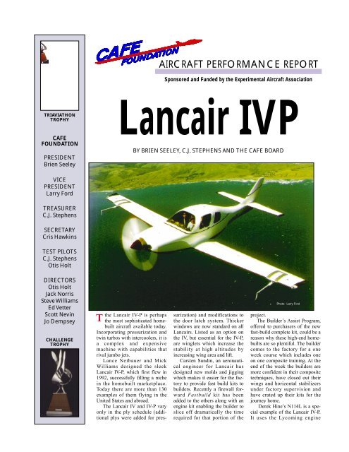
AIRCRAFT PERFORMANCE REPORTSponsored and Funded by the Experimental Aircraft AssociationTRIAVIATHONTROPHY<strong>CAFE</strong>FOUNDATIONPRESIDENTBrien Seeley<strong>Lancair</strong> <strong>IV</strong>PBY BRIEN SEELEY, C.J. STEPHENS AND THE <strong>CAFE</strong> BOARDVICEPRESIDENTLarry FordTREASURERC.J. StephensSECRETARYCris HawkinsTEST PILOTSC.J. StephensOtis HoltDIRECTORSOtis HoltJack NorrisSteve WilliamsEd VetterScott NevinJo DempseyCHALLENGETROPHYTthe <strong>Lancair</strong> <strong>IV</strong>-P is perhapsthe most sophisticated homebuiltaircraft available today.Incorporating pressurization andtwin turbos with intercoolers, it isa complex and expensivemachine with capabilities thatrival jumbo jets.Lance Neibauer and MickWilliams designed the sleek<strong>Lancair</strong> <strong>IV</strong>-P, which first flew in1992, successfully filling a nichein the homebuilt marketplace.Today there are more than 130examples of them flying in theUnited States and abroad.The <strong>Lancair</strong> <strong>IV</strong> and <strong>IV</strong>-P varyonly in the ply schedule (additionalplys were added for pressurization)and modifications tothe door latch system. Thickerwindows are now standard on all<strong>Lancair</strong>s. Listed as an option onthe <strong>IV</strong>, but essential for the <strong>IV</strong>-P,are winglets which increase thestability at high altitudes byincreasing wing area and lift.Carsten Sundin, an aeronauticalengineer for <strong>Lancair</strong> hasdesigned new molds and jiggingwhich makes it easier for the factoryto provide fast build kits tobuilders. Recently a firewall forwardFastbuild kit has beenadded to the others along with anengine kit enabling the builder toslice off dramatically the timerequired for that portion of thePhoto: Larry Fordproject.The Builder’s Assist Program,offered to purchasers of the newfast-build complete kit, could be areason why these high-end homebuiltsare so plentiful. The buildercomes to the factory for a oneweek course which includes oneon one composite training. At theend of the week the builders aremore confident in their compositetechniques, have closed out theirwings and horizontal stabilizersunder factory supervision andhave crated up their kits for thejourney home.Derek Hine’s N114L is a specialexample of the <strong>Lancair</strong> <strong>IV</strong>-P.It uses the Lycoming engine
installation developed by Brent Regan anddescribed here in the pages of SportAviation in December 1996.Basically, Brent modified the LycomingTIO-540, which is a rear mount engine, tocomply with the bed mount design that<strong>Lancair</strong> incorporated for the standardContinental TSIO-550-B. Although comparablein power, the Lycoming has a largerdiameter crankshaft which is beneficialfor running at high power. The enginecompression ratio is also increased to8.5:1, permitting less boost pressure forthe same or better performance.All of these changes required that Brentdesign and build a custom engine oil sumpthat puts the engine mounts and propellerthrust line in the same place. The entirealuminum induction and stainless steelexhaust systems were redesigned andhandcrafted by Brent to include Garret turbochargers,intercoolers and associatedplumbing. He also designed a snazzy carbonfiber plenum chamber which reducesengine operating temps while minimizingcooling drag. In addition, the entire electricaland ignition systems were alsoredesigned. Brent contributed many othermodifications to both his own and Derek’splanes.SUBJECT<strong>IV</strong>EEVALUATION<strong>Lancair</strong> <strong>IV</strong>-P, N114LBY C.J. StephensFirst ImpressionThe <strong>Lancair</strong> <strong>IV</strong>-P stands tall on its tubular,low drag landing gear. Noticeablyabsent are the landing gear doors that arenormally attached to the landing gear legs.This gives the airplane an almost spindlyappearance. The sleek, and sturdy steellegs, with the gear doors flush to the fuselage(except during the retraction/extensioncycle) adds to the flowing clean linesof the airplane. I found the operation of themain gear doors to be both innovative andsimple. The doors are held firmly shutwith springs and a tension strap. The doorsare held closed with springs and a tensionstrap that the gear leg engages when thegear is up. On extension, the gear legopens the door by pushing against a wearstrip in the door and a small elliptical holein the front of the door allows the doors toclose again with the gear down and locked.On retraction it all works in reverse.The next impression of the airplanecomes from the smooth flowing, high rise,contour of the fuselage. All of the externalsurfaces blend with each other and are finishedperfe c t l ysmooth. Thepaint isblemish freeand regardlessof theamount ofsearchingthere is nota singleimperfectionnoted inthe constructionor finish. This <strong>Lancair</strong> is largerthan most other homebuilt aircraft, butthen, this is no ordinary homebuilt.OverallLocated on each side of the front cockpitis a side-stick for control of the aileronsand elevators. Both sticks are cantedinboard to match a natural grasp of thepilot’s hand. It pivots at the base and haslight and equal motion of about three inchesin all directions.As reported in the <strong>CAFE</strong>’s Cozy article(April 1999 issue of Sport Aviation,) thereare many advantages of the side stickflight control. Wrist motion controls operationrather than upper arm movement asin most stick controlled aircraft. Thisallows precise but small motion to beexerted on the controls. It may not be at allfair to measure and compare the stickforces of this type of control with those inconventional center stick (arm movement)since they involve such different leverages.We have, however, measured andreported the stick forces later in this reportfor general information and comparison.An electric motor and pump provideshydraulic pressure to operate the landinggear and flaps. No parking brake isinstalled on the self-contained hydraulicLarry Fordtoe brakes. Ninety-four gallons of fuel iscontained in the wing and selectable by aleft/right/off valve on the lower centerconsole. All 94 gallons of fuel are usable.Ground HandlingEven with the hefty empty weight of2212.5 lbs it is possible for one person topush or pull the airplane, although itrequires a pretty good shove and a smoothlevel surface to do so. Getting into thecockpit requires either a knee to get up onthe wing, or to sit on the leading edge andthen stand up. There is no anti-skid “wingwalk” which added to the good lookingsmooth surface, however it also necessitatesthe placement of a protective pad onthe wing to keep from scratching the paint.Once on the wing it is easy to step directlyonto the floor of the cabin without steppingon the upholstery of the seat. Theerect seats put all occupants in a conventionalupright sitting position. All fourseats are comfortably padded withTemperfoam which is most appreciated onlong high altitude flights.The ignition system on N114L is a conventionaldual magneto set up. Therewould be little advantage to be gained withthe installation of electronic ignitions sincesea level manifold pressures are nearlyalways attainable, negating some of theadvantages of ignition advance. The injectedTIO-540 Regan/Lycoming engine has apurge valve installed to purge any air outof the injector lines prior to start. This wasvery effective during those difficult hotstarts. To operate the purge system, oneonly needs to turn on the low boost pumpfor about 20 seconds with the purge knobpulled out. This circulates cool fuelthrough the injector lines, purging the airand vapor out. The fast spinning starteralso aids in the quick start of a hot engine.Taxi operation is very easy with toe
Larry FordJo DempseyMain gear, emptyNosewheel, emptyPilot, front seatPassenger, front seatPassenger(s), rear seatsFuel, wing tanks fullOil, included 6.5 qt.Baggage, aft limit 140 lbTOTALSDatum = a pt. fwd of firewallc.g., inchesc.g., % aft of fwd limitGross weight, lbGross weight, landing, lbEmpty weight, lbUseful load, lbPayload, lb, full fuelFuel capacity, gallons*Empty weight c.g., inchesc.g. range, inches*as determined by <strong>CAFE</strong>Weight, lb1606.5606.0170.0170.080.2564.30.00.03200.090.8855%3200.02900.02215.5984.5420.294.0587.5386.5-94.5Larry Ford<strong>Lancair</strong> <strong>IV</strong>P N114L, Sample c.g.Arm107.6334.2598.0098.00129.0094.800.00140.00brakes located on the rudder pedals forsteering and stopping control. The planemoves easily, and comfortably holds normaltaxi speed with about 1,000 rpm. Anexcellent laminated checklist is providedby Derek which is easy to follow.Prior to take off an important item is tolock the one entry door located on theleft side of the fuselage. The door isheld in place with two hinges and eightsturdy latches and is operated by twolever type handles that snapped overcenter with a positive locking motion.The outward forces on the door aretremendous once the 5.2 psi cabin pressureis reached at flight altitude. All ofthe mechanisms holding the door inplace during flight appeared to be builtstrong enough to do the job without fail.A flat door seal, to help maintain cabinpressure, is mounted in the channel thatmates with the door and is inflatedpneumatically prior to takeoff. Thisplane was pressure-tested on the groundat 7.5 psi to verify a good safety margin.A light on the enunciator panel notifiesthe pilot if the baggage door is notproperly locked. This seems like a goodidea since it is not visible from the cabinand could be overlooked until aftereveryone is strapped in for flight. Thebaggage compartment is eye level andspacious but un-pressurized.Take off and climbA flap setting of 10 degrees, as notedby a paint stripe on the flap hinge or bythe flap indicator, is used for take off.The boost pump needs to be on at thelow setting until reaching 1,000 feet ofaltitude. Full throttle holds 35 inches ofmanifold pressure, 2700 rpm, and a fuelflow of 40 gallons per hour. The airplanetracks straight down the center of therunway with only light rudder pressurerequired to maintain directionalcontrol. Moderate rotation producesa nice liftoff which quicklyMoment turns into a substantial climb rate.172894 After becoming safely airborne20757 the landing gear and flaps are16660 raised, followed by a power16660 reduction to 32”/2500 rpm which10346 reduces the fuel flow to 25 gph. A53496 waste gate holds manifold pressureconstant during the climb; a00 nice feature that keeps the pilot290813 workload to a minimum. Since themanifold pressure holds constantduring the climb, it eliminates therequirement of constantly addingthrottle or leaning the mixture.The next necessary adjustment ofthe throttle or mixture is at leveloff.Cabin PressurizationSystemThe <strong>Lancair</strong> received an extrameasure of design engineering in order tomake it a safe pressurized airplane forflights at higher altitudes. By using airpressure from the turbo-charger, a pressurizationdump valve (regulated to 5.2 psimaximum), installing sturdy latches tohold the cabin entry door against the outwardpressure, and an inflatable rubberdoor seal to minimize leaks, this airplaneis able to produce a comfortable environmentfor the occupants. It eliminates therequirement of wearing oxygen masks duringflights at high altitude provided thesystem operates normally. Emergencydescent oxygen and masks are availableshould a situation occur that caused cabinpressure loss. The added material requiredfor pressurization and the lack of air noisefrom the air-sealed cabin contributed to anoticeably lower noise level than would beexpected.A flapper valve located above the rearseat automatically activates during thetransition between pressurized and non-ABOUT THE BUILDERDerek Hine is the talentedowner/builder of the <strong>Lancair</strong> <strong>IV</strong>-P featuredin this article. Derek began hiscareer in aviation at the early age of16 as an aeronautical engineerapprentice at Armstrong WhitworthAircraft, Ltd. in Coventry, England.He attended college at the same timeearning the equivalent of a bachelor’sdegree in Aeronautical Engineeringand his master’s in MechanicalEngineering. He has worked for overthirty years in mechanical engineeringand management involving aerospace,vehicles, lasers and semiconductors.Included in his accomplishments isthe design and construction ofNASA’s Mobility Test Article details,a vehicle designed to simulate themoon’s gravity and give astronauts“driver’s training”.Derek has logged about 3000hours of single and multi-engine flying.He chose the <strong>Lancair</strong> <strong>IV</strong>-P tobuild based on the aircraft’s performance.Getting places fast is high onhis list! He also needed a four-placecabin and the pressurization optioncapped off his decision process. He isdelighted with the results whichearned him an award for outstandingworkmanship at Oshkosh ‘98.His advice to builders is that theplane will go together the way themanual suggests it will. And, that abuilder can finish the project in thetime suggested by the factory, ifyou’ve built a plane before; but if it’sa hobby, then you’re likely to put inextra time anyway.
pressurized flight and causes muffledbanging sounds during flight which wassomewhat distracting.Trim SystemElectric trim is installed in all threeaxes. The hat switch at the top of the controlside stick operates the elevator andrudder trim tabs. A spring loaded threeposition rocker switch on the right instrumentpanel operates the aileron trim tab.Considerable rudder trimming is requiredas power and airspeed change since thetrim actuator operates quite slowly. Anelectronic device was installed that doublesthe rate of travel of the elevator trimduring times when the landing gear isextended. This helped, but the rudder stillseems to require a lot of trimming duringthe many maneuvers performed on theflight tests.Static Longitudinal StabilityThe static longitudinal stability, speedstability, was evaluated by fully trimmingto 170 KIAS then changing the airspeed in10 knot increments throughout the entireattainable envelope, without retrimming,and measuring the amount of stick forcerequired to hold level flight. The resultantcurve indicates the airplane’s tendency toreturn to its trimmed airspeed. The greaterthe tendency to return, the greater the staticstability. Figure _____ shows the elevatorstick forces recorded during this evalualtion.As the airplane’s center of gravityshifts to the aft, the static stability isreduced resulting in less stick forces orlower a stability margin. There was a veryslight reversal of stick force gradient at theslowest airspeed measured during theexploration of the forward center of gravity;however, it was minimal and not consideredto be a problem.During the aft center of gravity measurementsthere was a considerable reductionof the stick force required to maintainlevel flight, even though only at 84% aftwithin the allowable limits. Upon reaching90 knots airspeed, with only 50% of thehigh stick force (1.5 lbs at 90 knots)Photo: Larry Fordremaining (3.1 lbs at110 knots), I terminatedthe test anddecided not to attempta stall series. Tests ofthis nature (aft CGstalls) are beyond thetime and scope andequipment of the<strong>CAFE</strong> <strong>Foundation</strong>evaluation and shouldalways be approachedwith respect and caution.Turbo-Charger OperationI don’t recall ever seeing a nicer installationof a turbo-charging system as far asuncluttered equipment inside the cowlgoes. The exhaust plumbing seems tightand about as simple as the system could bedesigned. There is one compact turbo nicelyinstalled on each side of the engine atthe aft end of the header that exhausts thethree cylinders on that same side. It eliminatesall of the crossover plumbing that isusually associated with single turbo installations.Flying with a turbo-charged engine issomewhat differentfrom the pilot’s pointof view. A largeamount of heat isbuilt up within theturbo system andmust be dealt with toprevent mechanicalproblems. A consciouseffort must bemade to cool theengine and turbo aspower is reducedfrom cruise settingsto descent, landingand shut down.Turbo-chargedengines also tend tocause greater difficultyduring hot startsfor many pilots. Thepurge valve mentionedearlier seemsto eliminate the startingdifficulty problem.On the good sidethough, besides theobvious ability to getgreater power from agiven engine size andmaintain greaterpower to higher altitudes,the throttleremains right at theset manifold pressureduring climb. If 32”of manifold pressure is set for climb, thatnumber remains constant all of the way tothe top of the climb without having toreadjust throttle; even if your level off isup in the flight levels. Also, since thepower, manifold pressure, and rpm remainconstant, there is no need to adjust themixture until the throttle is re-set.Maneuvering stabilityAn examination was made of the elevatorforces on the control stick as the aircraftis turned at an increasing G force tomeasure the tendency of the airplane toreturn to level flight after displacement.Measurements were made in clean configurationat 170 KIAS, and with landingconfiguration at 100 KIAS, during flightsat a forward CG and at an aft CG. Thegraph_____ shows that the <strong>Lancair</strong> has astrong dynamic stability in each of themodes sampled.Spiral stabilityTo measure the airplane’s natural tedencyroll out of a bank or to over bank,known as spiral stability, the airplane wasfully trimmed and set into a 15 degree
Larry Ford photoscabin pressurization system fail.It is my opinion that even pressurizedflights above 25,000 feet should only be3530252015105Elevator Stick Force, lbs.Ο∆∇FΧBFΟ∇∆<strong>Lancair</strong> <strong>IV</strong>P, fwdc.g., 170 kts.<strong>Lancair</strong> <strong>IV</strong>P, aftc.g., 170 kts.<strong>Lancair</strong> <strong>IV</strong>P, fwdc.g., 100 kts.RV-8A, fwd c.g.,140 IASW10 @ 18% MACB Cessna 152BΟF∇∆ΧBF0 Ο∇ΧFB∆1 1.5 2 2.5 3 3.5Load in G'sManeuvering stabilityΟ∆FΟΧ∆attempted by the most experienced andprepared pilots. If a cabin pressure leak oran engine failure occurs, the results can bedisastrous without the immediate implementationof the proper breathing equipment.The oxygen equipment available inmost general aviation airplanes is less thanadequate for unpressurized flight above25,000 feet. The survival problem is furthercompounded in that the time todescend to a safe altitude becomes excessiveshould a pressurization failure occurat altitudes above 25,000 feet.<strong>Lancair</strong> N114L climbed smartly to24,000’ maintaining 32”/2400 rpm all ofthe way. While level at that altitude Iadvanced the power and easily attained35”/2700 rpm. Although I did not attemptto climb higher, it seemed to me that theplane could reach on the order of 35,000feet with little difficulty. The 5.2 psi pressuredifference between the inside and theoutside pressure provided a comfortable8,000’ cabin while operating at 24,000feet.This is where you fully realize that ‘thisis a significant airplane’. Here is a homebuiltairplane flying at four nautical milesof altitude, at 310 KTAS with cruise powerof 30/2500. It was indicating 185 KIASand handled quite nicely. This speed calculatedto .53 MACH.N114L develops a very mild divergentmovement in pitch and roll in level flightwith smooth air starting at altitudes above12,000’. The intensity increases steadily asthe altitude increases. It is quite mild andmight not even be noticed below 20,000’ ifthe airplane was flying in any turbulenceor was on autopilot. The only times that Iobserved this event was while flying at185 KIAS and at high altitude. The motionwas an exaggeration of any input in pitchor roll. By that I mean, if I made a normalsmall control input it seemed to be morethan was needed. It was as if the planebecame more sensitive to the controls.I had the opportunity to discuss thisoversensitivity with Dave Morss, who hasconsiderable experience in <strong>Lancair</strong> <strong>IV</strong>P.He indicated that this trait was commonlyknown by those who fly the <strong>IV</strong>P and thatthe installations of winglets eliminates thisphenomenon.DescentsTurbo-chargers operate at a high temperatureand need special attention to coolthem properly as the power is reduced justprior to and during descent. The generallyaccepted method is to reduce the power inseveral small steps so as not to rapidlyshock the system or cause carbon build up.This becomes a planning item, especiallywhen you figure that you may be at 24,000feet altitude requiring about 100 nauticalmiles of descent. The speed brakes workwell to expedite the descent but it causessome aerodynamic rumbling within theairframe while extended at high speed.Drag Producing DevicesAt given airspeeds drag producingdevices were extended and measurementswere made of the increase in rate ofdescent that was produced by that devicewhile keeping all else constant. All testswere commenced from level flight andconstant power. The amount of drag isexpressed in terms of rate of descent afterthe descent stabilized. (See the tabulardata.)During the fully-instrumented flights atthe <strong>CAFE</strong> test facility the laptop computerin the cockpit shows a continual readout ofthe glide ratio. It is interesting to note thedramatic increase in the glide ratio in apower off glide with the only difference
eing that propeller control is pulled fullback. Should the pilot ever be faced withneeding to stretch the glide it would certainlybe an advantage to remember thebig improvement with the propeller fullcoarse.Traffic pattern/ landingThe beautiful Fowler flap design adds tothe total wing area when extended and isvery effective in reducing the approachand landing speed as reflected on thegraph of stalls. Extension of the flap isquite slow causing no associated pitchchange with their operation. A paint markon the flap leading edge, visible from thecockpit, indicates 10 degrees flap deployment.This amount of flap can be used ashigh as 174 knots. As the flaps extend tothe full down position the drag increases toa comfortable lift and drag combination.This is reflected by the nominal powerrequired on final approach with gear andfull flaps down. Flap retraction, however,is very quick and in flight causes a noticeabledrop which must be allowed for duringa go around situation. Early flap retractionis not recommended.<strong>Lancair</strong> <strong>IV</strong>PN114L ASI calibrationCabin Baro #1 hassame pitot/staticas panel ASIWing Baro #3 usesa calibrated, certifiedgimbaled pitot/staticPanelIAS, kts66828590100110120130140150160170180190200210220CabinBaro,mphnana99.0103.8116.2127.6138.5151.0162.4174.6185.5195.8205.1220.7234.1248.0260.6The work load in thepattern is no more that inany other complex airplane.The visibility isexcellent and with the 10degree flap setting availableas high as 174 KIASthere is never the feelingthat the plane is behindthe power curve on downwindleg. The low drag ofthe landing gear requiresvery little additionalpower to compensate,once extended. The flapextension, base turn, and turn to finalapproach all fall well within the normalrange and feel solid and straight forward.The handling seemed to be best at 100KIAS on final, arriving at the flare at 85KIAS and reducing the power to idle.Flare out and touch down seemed easy tomanage once I got used to the length of themain landing gear. My initial tendencywas to touch when I thought I was still 2feet in the air, however by the third landingthe whole process was producing predictablysmooth landings.During the landing roll out, the weightof the airplane became evident with a littlemore than normal braking required to stopthe airplane. After landing a full four minutesof engine run at idle power was recommendedto dissipate the engine/turboheat prior to shut down.ConclusionsThe <strong>Lancair</strong> <strong>IV</strong>-P is a beautiful four passengerairplane that is for the serioushomebuilder. It is intended to make longtrips at a fantastic speed. It is capable ofcarrying all of the equipment necessary todo whatever level of flying might beintended. It isCAS inmph,Wing Baro76.389.994.6100.2111.9122.6133.7145.8157.8170.2180.3191.2201.2216.2229.8243.8255.9Config.dirty stallclean stallnot withineveryone’s budgetto build andfly such an airplane,but if youdo get thechance to, youwill truly enjoythe experience.The installationof cabin pressurizationallows flightabove much ofthe turbulenceand a lot of theunpleasantweather, addinggreatly topassenger comfort.My specialthanks to DerekROLL RATE, deg./second, includes input timeVa<strong>Lancair</strong> <strong>IV</strong>P N114L 79 Rt./ 90 Lt.RV-8A N58VA 109 Rt./102 Lt.Cessna 15247RANS S-7C 61 Rt./63 Lt.52 Rt./50 Lt.GlaStar**full flaps, 80 IAS1.3 Vso70 Rt./ 56 Lt.78 Rt./80 Lt.**3450 Rt./53 Lt.47 Rt./43 Lt.Hine for allowing the <strong>CAFE</strong> <strong>Foundation</strong> totest his gorgeous airplane. It is perfectlybuilt, beautiful to look at and a joy to fly.THANK-YOU, Derek.
LANCAIR <strong>IV</strong>P, N114L, SPECIFICATIONSEmpty weight/gross weightPayload, full fuelUseful loadENGINE:Engine make, modelEngine horsepowerEngine TBOEngine RPM, maximumMan. Pressure, maximum, 2 min.Turbine inlet, max/cruise/climbTurbochargerWastegateStarterAlternatorCyl head temp., maximumOil pressure rangeOil temp., maximumFuel pressure range, pump inletWeight of prop/spinner/crankInduction systemInduction inlet areaExhaust systemOil capacity, type, coolerIgnition systemCooling systemCooling inlet areaCooling outlet areaPROPELLER:MakeMaterialDiameter/PitchProp extension, lengthProp ground clearance, full fuelSpinner diameterFuel systemFuel pumpFuel typeFuel capacity, by <strong>CAFE</strong> scalesFuel unusableFlight control systemBraking SystemTire size, mains/noseSeatsCabin entryWidth at hips, front/rearWidth at shoulders, front/rearHeight, seat to headlinerBaggage capacityBaggage door sizeBaggage lift over heightStep-up height to wing step/T.E.2215.5 lb/3200 lb420.2 lb984.5 lbRegan Lycoming TIO-540 with 8.5 :1 c/r pistons360 BHP by dynona2700 RPM35 “ Hg.1650 °F/1550 °F/1450 °FGarrett 466642-9005Garrett 481064-9002B&C BCS206-149-24VB&C L-60 28 Volt, 60 Amp475˚ F30 - 60 psi245° FnanaBendix RSA-10 AD1 fuel injection11.5 sq in3 into 1 into turbo, each side, auto wastegates10 qts/Shell 15/50Bendix 1200 seriesDowndraft air, hot accesssory section77 sq in88 sq in, inc. 2 3 in ext. pipesMT 4 blade, 195-30A blade (experimental)composite78 inna12 in16 in2 wing tanks (L, R shutoff), FlowScan gph2 Duke 5134 elect. pumps, hi/lo press100 LL94.05 gal8 ozpushrods for aileron/elevator and cable for rudderCleveland disc, single caliper dual puck6:00 x 6 x 15/500 x 54gull wing door, pilot’s side37 in46 in37 in13.5 cu ft and 150 lb23w x 19h47 in19 inFLIGHT TEST DETAILSOne performance flight was made duringMay, 1999, in day VFR conditions. AFlowscan 201A fuel flow transducer wasused for the gph determinations and wascalibrated by measuring the weight of fuelburned on each flight. A PropTach digitaltachometer was mounted on the top of theinstrument panel. The performance dataflight was conducted with pilot and flightengineer aboard and flying qualities wereevaluated with other solo flights using ananalog G meter and Brooklyn Tool & MachineCo., Inc. NJ hand-held stick forcegauge.Cruise flight data was obtained withthe wingtip <strong>CAFE</strong> Barograph (#3)mounted on a wing cuff with a dummybarograph and cuff mounted on the oppositewing. These were correlated with thepanel airpseed indicator to produce theairspeed correction table shown here. Ourdata suggest that Vy is 135 mph CAS andVx is 105 mph CAS.Cowl exit temp (C.X.T.) is a functionof the OAT & CHT and is a measure ofthe efficiency with which the cooling systemremoves heat from the hot engine.This can be expressed as the temp rise relativeto the hottest CHT observed duringclimb:<strong>CAFE</strong>HONORARY ALUMNISteve Barnard--RV-6AJim Clement--Wittman TailwindJim Lewis--Mustang IIKen Brock--Thorp T-18Larry Black--Falco F.8LChuck Hautamaki--Glasair IIIJeff Ackland--LegendJerry Sjostrand--ExpressRandy Schlitter--RANS S-7CStoddard Hamilton Aircraft, Inc. GlaStarFred Baron--<strong>Lancair</strong> 320Mark Beduhn--Cozy Mark <strong>IV</strong>Dick VanGrunsven--RV-8ADerek Hine <strong>Lancair</strong> <strong>IV</strong>-P
COMPARAT<strong>IV</strong>E AIRCRAFTFLIGHT EFFICIENCY, INC.The <strong>CAFE</strong> <strong>Foundation</strong>:A Non Profit, All Volunteer, Tax-exemptEducational <strong>Foundation</strong>4370 Raymonde WaySanta Rosa, CA. 95404.FAX 707.544.2734Aircraft Test Facility, Santa Rosa Airport707/545-<strong>CAFE</strong> (hangar, message)IMPORTANT NOTICEEvery effort has been made to obtainthe most accurate information possible.The data are presented as measuredand are subject to errors from avariety of sources. Any reproduction,sale, republication, or other use of thewhole or any part of this report withoutthe consent of the ExperimentalAircraft Association and the <strong>CAFE</strong><strong>Foundation</strong> is strictly prohibited.Reprints of this report may beobtained by writing to: SportAviation, EAA Aviation Center, 3000Poberezny Road, Oshkosh, WI.54903-3086.ACKNOWLEDGEMENTSThis work was supported in part byFAA Research Grant Number 95-G-037. The <strong>CAFE</strong> <strong>Foundation</strong> gratefullyacknowledges the assistance ofAnne Seeley, EAA Chapter 124, andthe Sonoma County Airport FAAControl Tower staff.SPONSORSExperimental Aircraft AssociationFederal Aviation AdministrationAircraft Spruce & Specialty Co.Aerospace Welding Minneapolis, Inc.Fluke CorporationCessna Aircraft CorporationB & C Specialty CompanyEngineered Software “PowerCadd” and WildToolsBourns & Son SignsAeroLogic's Personal SimulationWorks SoftwareCardinal Electronics--makers of PropTachFlowscan flow transducersDreeseCode Software at www.dreesecode.comKIT SUPPLIERNeico aviation, Inc.2244 Airport WayRedmond OR 97756541-923-2244 www.lancair.comCost of airframe materials, no engine or inst.Kit starts sold to dateNumber completedEst. hours to buildPrototype first flewNormal empty wt. per Owner’s ManualDesign gross weight, lb, Takeoff/LandingRecommended engine(s)WingspanWing chord @ root/tipWing areaWing loadingPower loadingSpan loadingAirfoil, wingAirfoil, design lift coefficientAirfoil, thickness to chord ratioAspect ratioWing incidenceThrust line incidence, crankshaftWing dihedralWing taper ratio, tip/root,Wing twist or washoutWing sweepSteeringLanding gearHorizontal stab: spanHorizontal stab chord, root/tipElevator: total spanElevator chord: root/tipVertical stab: spanVertical stab chord: averageRudder: average spanRudder chord, bottom/topAilerons: span/average chord, eachFlaps: span/chord, eachTotal lengthHeight, static with full fuelMinimum turning circleMain gear trackWheelbase, nosewheel to main gearAcceleration Limits per factory:AIRSPEEDS PER OWNER’S MANUALNever exceed, V neManeuvering, V aBest angle of climb, V xBest rate of climb, V yStall, clean, V sStall, dirty, V soFlap Speed V feOWNER/BUILDER N114LDerek Hine5 Hawk ViewPortola Valley CA 94028derekhine@aol.com 650-858-8456 hangarDESIGNER’S INFORMATION$104,500, incl wing mating and Fast-Build4501305000-600019922200 lb3200/2900 lbTeledyne/Cont. TSIO-550<strong>CAFE</strong> FOUNDATION DATA, N114L30 ft 1.25 in47.25 in/ 30.125 at tip joint98 sq ft32.6 lb/sq ft9.1 lb/hp30 ft 3 in/3200 lnLaminar Flowmax 2d lift design coef. 2.517% at root9:11.6 °1.5 ° to right3 °50.26 in/ 29.95 inat least 2 °-1.6 °Diff. braking, int. nose shimmy damperRetractable electro-hydraulically130.625 in27.125/ 16.25 in132.875 in12 in/ 6.75 in~56 in21.5 in14.5 in~19.25/~8.375 in67.25/5.375 in78.5/8.5/11 in24 ft 9.25 in8 ft 5.5 inna6 ft 10 in74 in+4.4 G/-2.3 G274 kts CAS170 kts CAS126 mph155 mph69 mph84 mph10˚ @ 174 kts CAS, 40˚ @ 132 kts CAS150 kts/ 165 kts CAS
Cruise data, mphConfig./flight #DADCAS,CAS,Densalt.,Dens.NewM.P.,RPM GPH MPG Weight,Range, **<strong>CAFE</strong>Endur.,CommentClockBarono cuffsft.ratioTASin. Hg.lb.milesscorehrs.<strong>Lancair</strong> N114L#1, with cuffs, Baro #302:22:09238.9247.061000.833270.631.6250523.311.631321034173.9Vmax 6000'94.05 gallons fuel cap.#1, with cuffs, Baro #302:55:51231.9239.683870.777271.830.2250022.612.030631071184.0Max cruise 8500'for computing range#1, with cuffs, Baro #303:00:16230.8238.4120150.693286.430.0249521.713.230521175214.2Max cruise 12000'5 gallons VFR reserve#1, with cuffs, Baro #303:09:10224.5231.7175650.578304.629.8253623.013.230301179224.0Max cruise 17500'Wing cuff#1, with cuffs, Baro #303:24:59206.5212.6250000.448317.529.8254922.314.229911268254.1max cont. cruisedrag penalty = 6.4 mph#1, with cuffs, Baro #303:25:56214.1220.6250000.448329.534.4273032.910.02988892192.82 minute limitat 212 mph CAS#1, with cuffs, Baro #303:29:22208.7214.9250000.448321.029.8260725.112.829801139233.62600 RPM cruise**TAS^1.3 x MPG/1000 #1, with cuffs, Baro #303:31:18206.9213.0250000.448318.130.2242025.912.329751094223.52400 RPM cruise<strong>Lancair</strong> <strong>IV</strong>P N114LFlight/Date Start time Presalt., ft. Densalt rangeWeight,lbCAS,mphTAS,mphfpmcommentClimbsRate of climb,31.6" MP, 2510 RPM, 25 gph, C.X.T. 205°F#1--5/15/9914:26:4466477508-900631211521741431.032.0" MP, 2510 RPM, 26 gph, C.X.T. 184°F#1--5/15/9914:37:3866067513-900231001631851314.031.6" MP, 2504 RPM, 25 gph, C.X.T. 184°F#1--5/15/9914:45:1765887509-902430851741981357.031.6" MP, 2507 RPM, 26 gph, C.X.T. 196°F#1--5/15/9914:51:0466767510-900130721401591491.0Best rateC.X.T. = cowl exit air temp.DescentsRate of sink,Deploy dive brake, Va, level flt.#1--5/15/9915:44:001663718031-171532955190251-903.0brake effect @ Va2.2" MP, 2400 RPM, 1.8 gph, C.X.T. 145°F#1--5/15/9915:50:231246713616-129772948135165-1918.0flat pitch, clean3.6" MP, 1500 RPM, 1.2 gph, C.X.T. 133°F#1--5/15/9915:51:031134912555-118622948135164-1039.0steep pitch, clean42" MP 1445 RPM 1 1 gph C X T 115°F#1--5/15/9915:53:5789059820-95472946123144-820 0min sink clean