High-Speed Propeller Noise Prediction—A ... - CAFE Foundation
High-Speed Propeller Noise Prediction—A ... - CAFE Foundation
High-Speed Propeller Noise Prediction—A ... - CAFE Foundation

You also want an ePaper? Increase the reach of your titles
YUMPU automatically turns print PDFs into web optimized ePapers that Google loves.
the noise-generationbe reducedto exerciseInthe lastcopyrightsaleU.S.copyrightassertedoperatingroyalty-freea schemenecessarydevisedAIAA JOURNALVol. 30, No. 7, July 1992<strong>High</strong>-<strong>Speed</strong> <strong>Propeller</strong> <strong>Noise</strong> <strong>Prediction—A</strong> MultidisciplinaryApproachMark H. Dunn*Lockheed Engineering & Sciences Company, Hampton Virginia 23666andF. FarassattNASA Langley Research Center, Hampton, Virginia 23665The prediction of noise produced by advanced propellers is a multidisciplinary subject which involves theaeroelasticity, aerodynamics, and aeroacoustics of rotating blades. As part of the PTA (Propfan Test Assessment)noise-prediction project of NASA Langley, state-of-the-art computational methods in these disciplineswere combined to form a comprehensive propeller noise-prediction package. The primary function oftheproject was to assess current noise-prediction capability. This was accomplished by comparing predictions withthe extensive noise data provided bythePTA flight tests of NASA Lewis. The emphasis of this paper isonfree-field predictions, which correspond to boom microphone measurements, and conditions for which theinflow is approximately axial. Predictions made on the fuselage of the PTA aircraft and predictions correspondingto nonaxial inflow conditions form the subject matter of companion papers by the authors and co-workers.Excellent agreement in trends and generally good agreement in acoustic levels between free-field measured andpredicted data were observed. A secondary goal ofathe project wasto study systematically the effect of bladedeformation on propeller aerodynamics and acoustics. The twist and camber distributions of advanced propellersare altered by centrifugal and aerodynamic forces. Consequently, blade surface pressure, power, andthrust are influenced by blade deformation. It was demonstrated that the impact of blade deformation onpropeller noise can be significant and should be included.IntroductionTWO desired characteristics of an aircraft propulsion systemare high efficiency andlow noise radiation. <strong>High</strong>propulsive efficiency results inlow cost. Low noiseradiation means community acceptance, passenger comfort,and lower aircraft empty weight due to the reduction of acousticinsulation inthe fuselage. Thus, the noise issue also haseconomic impact onthe and usage of aircraft.A very attractive propulsor for high efficiency is the propeller.Modern advanced propellers have high disc loading andoperate at supersonic helical tip speed. To reduce the radiatednoise, the blades are thin and highly swept. Although highpropulsive efficiency compared to current turbofans isachieved, the noise issue needs further attention. The currentadvanced turboprops generate high-intensity noise which mustbefore these propulsion systems are considered foruse in future airliners. Therefore, an important aspect ofadvanced propeller design is noise prediction.two decades, significant advances have beenmade in rotating blade noise prediction. It can be argued thatmechanisms of advanced propellers arefully understood. Sophisticated codes based onthe acousticanalogy are available for advanced propeller noise predictionwhich model the blade geometry and kinematics accurately.Presented as Paper 90-3934 at the AIAA 13th Aeroacoustics Conference,Talahassee, FL, Oct. 22-24, 1990; received March 11, 1991;revision received Dec. 12, 1991; accepted for publication Dec 12,1991. Copyright © 1992Astronautics, Inc. Nobythe AmericanInstitute of Aeronauticsandis inthe United States underTitle 17, U.S. Code. The Government hasa licenseal rights under the claimed herein for Governmentalpurposes. All other rights are reserved by the copyright owner.*Principle Engineer. Member AIAA.tSenior Research Scientist, Applied Acoustics Branch. AssociateFellow AIAA.1716These codes require as input the deflected blade coordinates,surface pressure, and the flow in the blade vicinity (if quadrupolenoise calculations are performed). These input datashould be provided from aeroelastic and aerodynamic codes.This indicates the multidisciplinary nature of propeller noiseprediction. In the past, various groups of researchers havedeveloped propeller aeroelastic and aerodynamic codes forblade flutter and integrity analysis and calculation of propellerpower, thrust, and efficiency. These codes could certainly beused for supplying input data to a noise-prediction code. Themain difficulties in doing so are that 1) the codes are notcompatible and, because the volume of data transmitted betweencodes is enormous, interfaces among codes must bedeveloped for automatic computer execution; and2) sincesome of these codes require considerable computational time,should be that reduces computer executiontime while maintaining a reasonable degree of accuracy.In 1988, a full-scale advanced propeller was extensivelytested under the Propfan Test Assessment (PTA) program byLockheed Georgia. These tests covered a large range of operatingconditions at various altitudes. Both external and cabinacoustic data were collected, as well as engine and propelleroperating parameters. The availability of these data providedan opportunity to evaluate the state-of-the-art of advancedpropeller noise prediction. Such a study was conducted as partof thePTA noise-prediction project of NASA Langley, inwhich the aeroelastic, aerodynamic, and acousticcodes were evaluated and linked by interfaces. A data managementsystem was developed for the project so that inconsistenciesinthe measured PTA data could be easily discovered andeliminated from consideration. In addition, various displayoptions, such as contour plots of noise intensity on the fuselage,are available from the data management system. Thecombined noise-prediction package, which includes the datamanagement system, state-of-the-art engineering codes, interfaces,and an executive system, was completed in April 1990.Since that time, large-scale automated predictions and comparisonwith experimental data have been attempted.
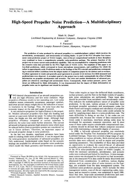
and seriesthe propellerand linkedThe primaryambientaverageseachbladepressureadditionDUNN AND FARASSAT: HIGH-SPEED PROPELLER NOISE 1717PTA Flight TestThe PTA flight tests were designed to evaluate the noisecharacteristics and structural integrity ofa single rotor, fullscaleadvanced propeller. 1 This propeller is designed for cruiseflight of Mach 0.8at 10.7 km (35,000 ft) altitude. The followingis a brief description of the test hardware, instrumentation,and procedure. Readers should consult the appropriateNASA Contractor Reports 1 ' 2 for more details.Advanced Propfan SR-7LThe advanced propeller, which was designed by HamiltonStandard, was of tractor type. It had eight thin, highly sweptblades using NACA series 16 airfoils in the outboard region65 circular arc airfoils inthe inboard region oftheblades, which had a 45-deg leading-edge sweep at the tip.Figure 1 shows this advanced propeller, known as the SR-7Lpropfan design, as installed onthe aircraft. The diameter ofwas 2.74 m(9ft) with the design disc powerloading of 257 kW/m 2 (32 shp/ft 2 ). The blades were made ofcomposite materials with a central aluminum spar.PTA AircraftThe testbed aircraft wasa Gulfstream Aerospace Gil businessjet aircraft (Fig. 1). The propulsion system for the propfanwas installed onthe left wing. The power tothe propellerwas transmitted by a gearbox, and the direction of rotation ofthe propeller was clockwise viewed from a position ahead ofthe disc (i.e., rotating upward at the inboard side). The nacelletilt angle could bechanged from -3to+2deg(relative tothefuselage reference plane) to vary the inflow angle. In thispaper, the results of nacelle tilt angle of -1 deg are utilizedsince this tilt angle corresponds most closely to uniform inflowconditions.Fig. 1PTA aircraftFuselage surfacemicrophonesProp plane of rotationAcoustic boommicrophonesandthe large-scale advanced propeller.PROP PLANEDISTANCE TO PROPELLER TIP = 1.24B (1.70 m, 5.58 ft)FLUSH MICROPHONES(5 PLACES)- 5.52BFAIRING -BLADE LENGTH, B= 1.37 m(4.5 ft)LEFT WINGL BOOMREAR BEAM (REF)Fig. 2 Acoustic boom installation and microphone location.InstrumentationExtensive instrumentation was used inthePTA flight program.Some ofthe instrumentation wasforthe integrityevaluation. 1 ' purpose 2Forthe of this paper, only the externalacoustic instrumentation will be covered here. On the exteriorsurface of the fuselage and on a wing-mounted boom, Kulitemicrophones of diameter 0.254 cm (0.1 in.) were mountedwhich had an accuracy of 1 dB from flight to flight. Therewere five microphones on the tapered boom. Figure 2 showsthe boom design andthe microphone positions. The boom isat the same distance from the propfan axis as the line nearestto the propfan axis on the fuselage. Since we will not presentresults for individual microphones onthe fuselage, the microphonelocations will not be given here. (See Table B-l in Ref.1 for more details.) Some important engine and flight conditionswere measured during the tests by instruments carriedonboard the aircraft. These were propfan rpm, blade pitchangle, engine torque, power and speed lever positions, sideslipangle, indicated air speed and Mach number, aircraft e.g.vertical acceleration, andthe air and temperature.Test ProcedureBoth high-altitude and low-altitude flights were conductedwith various nacelle tilt angles. In to acoustic objectives,the evaluation of propfan behavior under a wide rangeof dynamic loading conditions wasof primary importance inthe flight program. We are concerned with high-altitude testsin this paper. Three nacelle tilt angles of-3, -1, and2degwere used in these tests. A large range of flight parametervariations were tested. For each test, blade stress, noise, andvibration were recorded at transducer point for approximately60 s. The jet engine on the port side of the aircraft wasoperated at the lowest power setting needed for level flight. Toevaluate the background noise, some tests were flown withpropfan blades removed.Data AcquisitionAcoustic data were recorded byFM recorders using theconstant-bandwidth frequency division multiplexing technique.HP model 3562 narrowband analyzers were used forspectral analysis with 40or50 inthe frequency rangeof 0-2000 Hz. The effective bandwidth of 3.75 Hz wasachieved. Forthe most part, time histories ofthe acousticsignals are unavailable. With one exception, only spectralresults are presented in this paper.PTA <strong>Noise</strong>-Prediction ProjectThe PTA noise-prediction project was conducted at NASALangley Research Center from January 1989 to December1990 and was staffed by the authors and two co-workers.Details ofthe project objectives andits development are presentedin this section.Objectivesobjective ofthePTA noise-prediction projectwas to evaluate the current status of noise-prediction technologyfor advanced technology propellers in actual flight. Thiswas accomplished by the development of a system noise-predictionpackage that incorporates state-of-the-art methods inpropeller aeroelasticity, aerodynamics, and aeroacoustics. Theapplicability of the prediction system was assessed by comparingpredictions with actual flight data from the PTA tests, onboth the acoustic boom and fuselage.An advanced time domain propeller noise-prediction code,based on the acoustic analogy, provides the cornerstone forthe system noise-prediction package. To be effective, thenoise-prediction code requires accurate blade geometry andaerodynamic loading input. Asa result, state-of-the-art propelleraeroelasticity and aerodynamics codes were identifiedtothe noise prediction code via software interfaces.
The bladesA secondaryFig.suppliedimportantpropellerbladestudyaugmentedaffectbasedbeenshownnoise.to NASTRAN,hot bladethe aerodynamicBLP thenfullcalculatedapproximateonlynumberaerodynamicscontinued.bladesubsonicaerodynamicpredict1718 DUNN AND FARASSAT: HIGH-SPEED PROPELLER NOISEThe scattering and refraction of incident acoustic waves by ahard surface such as a fuselage and its boundary layer are alsoimportant facets of system noise predition. Consequently, thenoise-prediction package was bythe inclusion ofacomputer code that models these propagation effects. Thefinal aspect of the development phase was the creation of anexecutive system that was designed to operate the codes andmanipulate input and output data.aimofthe project wasto the effect ofblade deformation on aerodynamics and Inthe past, because of the use of straight metal blades with lowdisc loading and relatively thick sections, blade deformationwas not considered an issue in aerodynamic andacoustic calculations. However, the new advanced propellercomposite blades are highly loaded, thin, swept, and twisted.can deform sufficiently to aerodynamics andnoise. A systematic study of this effect hasnot donebefore, and for this reason, was one of the objectives of thisproject.ProcedureThe comprehensive noise prediction package contains fourmajor computer programs. Blade-deflection calculations areprovided bythe aeroelastic code NASTRAN. blade elasticbehavior was bya preprocessor known as COB-3TheSTRAN 4 which utilizes blade structural design and materialproperties to generate elasticity data tobe used as input toNASTRAN. The output of COBSTRAN for SR-7L was obtainedfrom NASA Lewis Research Center foruseinthisAdamczyk'sproject. Blade surface pressures are supplied bypropeller aerodynamics code. 5 Free-field noise predictions arecalculated by the propeller noise-prediction code ASSPIN, 6and corrections due to the scattering and refraction of acousticalwaves by a hard cylindrical surface (fuselage or boom) andits boundary layer are determined by the code MRS-BLP. 7Brief descriptions of these codes are given inthe next subsection,andthe entire noise-prediction process is schematicallyin 3.Blade deflection and surface aerodynamics are coupledphenomena. This is because precise deflected blade coordinatescannot be calculated without a knowledge ofthe aerodynamicloads and vice versa. Consequently, accurate bladecoordinates and surface pressure data must be obtained by aniterative process between the aeroelasticity and aerodynamicscodes. The iterative procedure is ona similar processdeveloped by August et al. 8 and proceeds as follows: The firstiteration begins by executing NASTRAN without aerodynamicloads to get deformed (hot) blade coordinates due tocentrifugal forces only. The second iteration cycle is nowDEFLECTION & AERODYNAMICCALCULATIONSstarted by using the hot blade coordinates in the aerodynamiccode. The aerodynamic code itself requires many iterationcycles for convergence. Since at this stage, thehot bladecoordinates are approximate, the iterationcycles are stopped at a given cycle before full convergence.The resulting approximate blade loads arenow used as inputandnewhot blade coordinates are computedwhich now have the effects of centrifugal forces andtheapproximate blade loads. This completes the second aeroelastic-aerodynamiciteration cycle. The third iteration cycle isthen started by running the aerodynamic code with the latestcoordinates but starting the aerodynamic iterationcycle with the blade loads which were the resultof the previous aerodynamic calculation. Again, the aerodynamiciteration cycles are stopped before full convergence. Atthis stage, the blade loads are more accurate than those computedin the second aeroelastic-aerodynamic iteration cycle.NASTRAN is then run with the latest aerodynamic loads, anditeration is Convergence betweenthe two codes is attained when the angle athe15%radial station does not change appreciably. This usually occursafter three complete iterations. For this reason, aerodynamicloads at each iteration ofthe interaction process are calculatedusing only one-third ofthe of cycles normally neededfor full convergence ofthe code. Asa result,extraneous aerodynamic calculations are avoided and computationaltime is minimized.When the aeroelastic-aerodynamic iterations have convergedsatisfactorily, the hot blade coordinates and blade surfacepressures are used as input to the propeller noise codeASSPIN. This will give the free-field acoustics of the propeller.The results are compared with the measured acoustic datafrom the boom microphones after boom-scattering correctionsare applied tothe predictions. The boom-scattering correctionsare from MRS-BLP. To the propellernoise on the fuselage, ASSPIN is used to supply theincident pressure to MRS-BLP along the nearest line on thetop of the boundary layer parallel to the propeller axis. MRSgivesthe level of each harmonic ofthe noise onthefuselage surface.Code DescriptionsWe present a brief description of the codes used in theprediction procedure. Readers are referred tothe relevantreferences in this paper for more details.NASTRANThis code computes the blade deformation by centrifugaland aerodynamic forces. 3 The geometrically nonlinear (largedisplacement) analysis option of this code (NASTRAN SOL-64) is ordinarily used to obtain the aeroelastic computationsreported here. 9 The NASTRAN input was supplied by theComposite Blade Structural Analyzer (COBSTRAN) 4 whichcomputes the elastic characteristics of the blades based on thestructural design and materials of blade construction.Aerodynamic CodesThis code was developed by Adamcyzk and coworkers atNASA Lewis Research Center 10 and is based on the time-averagedEuler equation. flowfield 5Theis steady in timeframe fixed totheandperiodic azimuthally inthe rotating propeller.The finite volume method of Jameson based on a Runge-Kutta scheme is utilized in this code. An iterative procedure isused to solve the average-passage equation system through thepropeller. This code requires the propeller hub design for theblade load calculations.Fig. 3PTAnoise prediction procedure.ASSPINThis code was developed by Dunn etal. at NASA LangleyResearch Center. 6 ' this code, 11In the source formulation1-A 12 and transonic/supersonic source formulation 3 13 of
onthethe acoustica reasonabletothetopofthe boundaryPTA flightthe projectThe theoretical(35,000codeinflowderivedusingboundary-layerRawls,takenRef.the resultrapidshows% RadialinferredDUNN AND FARASSAT: HIGH-SPEED PROPELLER NOISE 1719Farassat are used with automatic switching between the formulationsinthe as needed. The formulations are basedFfowcs Williams-Hawkings (FW-H) equation withoutthe quadrupole term. Thus, the acoustic formulations fornoise generation are assumed to be linear. This appears to beapproximation because oftheuseof blades withvery thin sections. The computational methods employed, thealgorithm for coding, and sensitivity to time and surface meshsizes of ASSPIN are reported in Refs. 6and 11.MRS-BLPformulation forthe boundary-layer propagationcode was by McAninch 14andtheandcode, known as MRS-BLP, for a cylindrical fuselage wasdeveloped by Spence. problem 7The of wave propagation issolved in the frame fixed to the infinite cylinder with anincident wave prescribed on the top of the boundary layerfrom ASSPIN. The problem is solved in the frequency domainfor each harmonic of the blade-passing frequency of the incidentpressure. By using a Fourier transform inthe axial direction,a single linear ordinary differential equation is obtainedwhich is integrated numerically in the radial direction to findpressure onthe fuselage. incoming wave 14An ofunit amplitude is integrated outward from the fuselage surfacelayer, andthe amplitude is matchedto the incident pressure there by adjusting the wave amplitude.To save computation time, ASSPIN is only executed for observerpositions along a line on the top of the boundary layernearest tothe propeller axis. The incident pressure along thetop of the boundary layer around the remainder of the cylindricalsurface is reconstructed by Graf's theorem for cylindrical(Hankel) functions. 15 A users manual for the code can befound in Ref. 7.ResultsIn this section, results ofthe prediction effort correspondingtoa nacelle tilt angle of-1degathedesign cruise altitudeof 10.7 km ft)are presented. Measurements to validateuniformity ofthe velocity were not during thetests. Theoretical calculations performed by Lockheed,however, indicate that approximate uniform inflow conditionsexisted for many ofthe flight tests athe-1deg tiltangle. Predictions for nacelle tilt angles other than - 1 deg,corresponding to nonaxial inflow conditions, were a part ofandcanbe found in Ref. 16.Only the results for the acoustic boom are considered in thispaper. Reports by other members of the PTA noise-predictionproject team have been written in which fuselage predictionsand comparisons with PTA data have been conducted. In Ref.17, PTA measured data onthe fuselage were processed andanalyzed, and trends relating shaft horsepower, helical tipMach numbers, and angle-of-attack effects to fuselage noiselevels were established. By the boundary-layer propagationcode MRS-BLP, the effects of profile andthickness on fuselage noise were studied in 18.The operating conditions chosen for the studies consideredhere represent a wide range of propfan horsepower and tipspeeds and are shown in Table 1.Aeroelastic-Aerodynamic Interaction PredictionsThe effects of blade deflection on propfan aerodynamicsand noise are discussed in this subsection. As shown in theprediction procedure (Fig. 3), the aeroelastic-aerodynamic iterationscheme also hasa power loop in which the pitch angleat the 3/4 radial position, /3 3/4 , is adjusted so that the calculatedpower matches the measured power ofthe engine. Alofthe results presented in this subsection include the power loopcalculations.Results forthe design condition (condition 264) are consideredfirst. Figure 4 the results of several aeroelasticaerodynamiciterations on the twist-angle distribution of ablade. Note that the curve labeled centrifugal loads is theresult ofthe first aeroelastic-aerodynamic iteration in whichthe response due to the aerodynamic loads was not included.As expected, the outboard region ofthe blade is influencedmost by the deflection. The maximum change in twist is about4 deg (untwist) at the tip. As shown in Fig. 4, the aerodynamicloads produced only a small additional untwist. This curve isofthe third and final aeroelastic-aerodynamic iterationillustrating the convergence of this process.Figures 5a and 5b show the deflection of the camber bycentrifugal and aerodynamic loads at 81 and 100% radialpositions, respectively. Note that the vertical coordinate in thisfigure is exaggerated. Several results are from thisfigure. First, there is a change of up to 30% in maximumcamber, and this deflection has opposite sense in the tworadial positions. The camber is increased at the 81% locationand decreased at the tip section. In both cases, the effect of theO)0)Q8075706560555045UndeflectedDeflected - Cent. LoadsDeflected - Cent. + Aero. Loads40U.2 0.3 0.4 0.5 0.6 0.7 0.8 0.9 1.0 1.1StationFig. 4 Effects of centrifugal and aerodynamic loads on blade twistdistribution-design condition (condition 264).Table 1 Operatingconditions ofPTA aircraftused for predictionsaltitude = 10.7 km (35,000 ft)Condition264276348356357360361377378380383CO,m/s299.3299.3301.1301.0301.2301.1301.2302.4302.4303.5299.8PO,kg/m 30.3720.3700.3700.3680.3690.3680.3690.3670.3660.3640.369M F0.8140.8110.8080.8060.8020.8080.8050.7990.7970.8040.808Mip0.8140.8530.7570.8450.8470.7560.7580.6280.6260.6240.842rpm16961777158617701776158415891322131813181757J3.142.993.352.992.973.353.343.993.994.043.01C P1.730.372.110.770.371.010.470.701.623.201.56shp3029746300615277411426668570130825833089C T0.40-0.020.470.120.000.140.00-0.040.200.410.37183/4, deg57.751.360.352.952.154.554.155.458.062.654.3
most1720 DUNN AND FARASSAT: HIGH-SPEED PROPELLER NOISE0.0160.012K. 0.008E£ 0.004a) Camber Deflection @81% Radial Station145CD•o•5 140Io> 135PREDICTION - BOOM SCATTERING INCLUDED-o- Rigid blades"O" Flexible blades, centrif. loads-£r Flexible blades, centrif. +aero loads>§ 0.000occ-0.004-0.0080.0160.012-0.1 0.10.30.50.70.9UndetectedDeflected - Cent. LoadsDeflected • Cent. + Aero. LoadsRelative Chordb) Camber Deflection @ Tip Section1.12> 130D_T3g 1251202 3 4 5 6 7Harmonic NumberFig. 6 Effect of blade deformation on the acoustic spectrum ofboom microphone 3 [design condition (condition 264); power coefficient= 1.73 in all cases].0.0080.0040.000Fig. 5 Effect of centrifugalof blade camber.-0.004UndetectedDeflected - Cent. LoadsDeflected - Cent. + Aero. Loads-0.008-0.1 0.1 0.3 0.5 0.7 0.9Relative Chordand aerodynamicloads on deformationaerodynamic loading has been to reduce the camber. Also, itis seen that centrifugal forces account for ofthe chordwisedeflection. The smoothness ofthe deflected cambercurves seems to indicate that the deflection calculations arestable.Since the changes in blade twist and camber affect theaerodynamics, it is expected that there are differences in bladesurface aerodynamic loads if cold and hot blade coordinatesare used. Indeed, this is true. Using rigid (cold) blade coordinates,the predicted power coefficient forthe design condition(condition 264) was 1.99 which was 15% higher than themeasured power coefficient of 1.73. Note that to obtain thehot blade coordinates for use in the final aerodynamics calculations,airfoil thickness was added to the deflected cambershapes.A summary of aeroelastic-aerodynamic calculations correspondingtothe operating conditions of Table 1is given inTable 2. Table 2 shows the measured and predicted thrustcoefficient Cy, measured and predicted /3 3/4 , and predicted1.1o> 400Q.C °Dw -400-800V_L_L_L_\ 1 1 ^ 1_L _Vj \i ___L _ j _L _L _L _LPredicted SignatureBoom microphone 3, DesignFlight Mach no.= 0.81,Hel. tip Machcondition (cond. 264)no.= 1.15-12000.000 0.010 0.020 0.030 0.040Time (seconds)Fig. 7 Comparison of measured and predicted time histories forboom microphone 3 [design condition (condition 264)].untwist angle at the tip. The thrust coefficients were notdirectly measured during the PTA flight tests, but were estimatedfrom engine operating conditions. No assessment of thedegree of accuracy of C T measurements is available. The accuracyof 03/4 measurements is estimated to be ±1 deg (Ref. 2).From Table 2, it is seen that the untwist at the tip is betweenabout 2-4 deg for all conditions. Thrust coefficients are consistentlyoverpredicted, particularly for small values of C T . Asimilar situation exists for 0 3/4 , although there is no consistencyof behavior. Since the measurements of C T and 0 3/4 wereTable 2Results of aeroelastic-aerodynamic calculationsrpm CP CT CT 183/4, deg 183/4, deg Aj8 t i p , degCondition Measured Measured Measured Predicted Measured Predicted Predicted264276348356357360361377378380383169617771586177017761584158913221318131817571.730.372.110.770.371.010.470.701.623.201.560.40-0.020.470.120.000.140.00-0.040.200.410.370.470.070.580.230.130.270.100.190.390.570.4957.751.360.352.952.154.554.155.458.062.654.357.250.960.252.551.055.253.158.161.264.356.2-3.3-3.8-2.9-3.7-3.8-3.2-3.5-2.1-2.2-1.9-3.6
not precise,The impactcentrifugalpropellerdeflectionconsidered.M=0.8 AltitudeDistance<strong>Propeller</strong>the agreementasa 2-dBThe conditionlowereachshapeDUNN AND FARASSAT: HIGH-SPEED PROPELLER NOISE 1721the differences between measured and predictedquantities could be attributed to measurement errors.ofthe blade-deflection components, i.e., deflectiondueto loads and dueto aerodynamicloads, on noise isnow For this145140135130125120115PREDICTION - BOOM SCATTERING INCLUDEDo- Rigid bladesO" Flexible blades, centrif. loads&• Flexible blades, centrif. +aero loads2 3 4 5 6 7Harmonic NumberFig. 8 Effect of blade deformation on the acoustic spectrum ofboom microphone 3 [low aerodynamic loading condition (condition276); power coefficient = 0.37 in all cases].357+361+378+360+1000 2000Shaft Horsepower348+Fig. 9 Operating conditions for boom microphone directivity study(nominal flight Mach number = 0.8).purpose, two examples, corresponding to conditions 264 and276 of Table 1, are studied. All noise results discussed here arefor boom microphone 3 (see Fig. 2). Differences in aerodynamicloading are minimized by using the appropriate measuredpower coefficients.264 example is discussed first. Figure 6 presentsthe acoustic spectra using the rigid blade, blade deflectedby centrifugal forces, and blade deflected by both centrifugaland blade forces. For comparison, the measured acousticspectrum is also included. Note that a boom-scattering correction,calculated with MRS-BLP (see Ref. 19, Table 3), wasadded tothe predicted spectra forthe first three harmonics.For higher harmonics, a 6-dB correction was used. This figureshows that blade deflection, in thiscase, can producelevels oftheasdifference in some ofthe harmonicacoustic spectrum. In addition, the acoustic spectra of flexiblemuchblades with and without blade loads are very close. Comparisonwith the measured acoustic spectrum shows that, exceptfor the third harmonic, the inclusion of blade deflection hasimproved the prediction. In Fig. 7, the measured and predictedacoustic pressure signatures are displayed.Itis seenthatis very good, both in peak values and ofthe signature. Note that no scattering correction is applied tothe predicted signature.Figure 8 shows the boom microphone 3 acoustic spectra forrigid and flexible blades for condition 276 (see Table 1).Again, a measured spectrum is included. For this condition,the propeller operates at low power coefficient relative to theprevious example. This figure is shown to indicate that bladedeformation can have a very significant influence on the levelof some harmonics. For example, the fourth harmonic levelfor the rigid blade is about 10dB than that oftheflexible blade. The difference for most of the other harmonicsis also significant. Another important point to note is that theinclusion of blade aerodynamic loads inthe deformation calculationis important for the first harmonic level. For otherharmonic levels, it does not appear to be significant. Theinclusion of deformation, particularly by blade loads, inacoustic calculations have improved the prediction for allharmonic levels except the sixth and seventh.Boom-Directivity PredictionsThe results and discussions presented in this subsectionconcern the last nine conditions in Table 1. The flight Machnumber ofthe aircraft was approximately 0.8 for case inX == 35,000 ftR= BladeAlong Boom (X
and shaftnoise1 oToMachacousticM=0.8 AltitudeFor example,are given.Tablealmostboom1722 DUNN AND FARASSAT: HIGH-SPEED PROPELLER NOISE= 35,000 ft R= Blade Length =4.5ftX = Distance Along Boom (X < 0 Aft of <strong>Propeller</strong> Plane)Ibo01357 356 383iOoco>01X/RX/R1000 2000Shaft Horsepower3000Fig. lOb Comparison of measured and predicted axial directivity for boom microphones corresponding to operating conditions of Fig. 9 (secondharmonic).M = 0.8 Altitude = 35,000 ft R = Blade Length = 4.5 ftX = Distance Along Boom (X
our predictionsand2) scatteringThe majorForthe secondgeneral,thirdaboutexcellentnacellenacelleflownacellepredictedtrendseffectspropellerboth(tobeApplicationSucci,codesvarioussuchthisDUNN AND FARASSAT: HIGH-SPEED PROPELLER NOISE 1723Condition348356357360361377378380383Table 3 Measuredresults of fuselage microphonecorresponding to boom microphone 11 x BPF,adBa Blade passage frequency131.4134.6135.7132.2133.8126.2127.8129.2134.12 x BPF, dB123.0125.3127.3125.1124.5118.6119.1118.1122.93 x BPF,dB115.3112.4118.3118.4118.6112.1————113.2much higher than that measured at boom microphone 1, lendingsupport to the proposed microphone malfunction. Thelevels measured at boom microphone 5 were most likely affectedby reflections from the and wing leading edge.and harmonics, the peaklevels are, in closer to measured levels. The maximumdiscrepancy is 5dBforthe peak values. The directivityshapes are good except for the microphone 5 position and forthe lowest rotational tip Mach number of 0.65 at all enginehorsepowers. This sudden rise in directivity is unexplained andis perhaps due to nonuniform inflow. The fact that there isnow underprediction at microphone 1 supports this suspicion.Concluding RemarksIn this paper, we have used a series of flight test acousticdata of an advanced propeller to assess the current capabilityof propeller noise prediction. The best available aeroelastic,aerodynamic, and acoustic codes were employed for this project.Only acoustic data for uniform inflow cases have beenused in the study presented here. Direct measurement of inflowparameters wasnot available, and there are reasons tobelieve that uniformity of into the was onlyapproximated in these tests fora tilt angle of-1deg.Some predictions involving nonuniform inflow conditionswere calculated as part ofthe PTA noise-prediction projectand are reported elsewhere. An extensive study such as thatperformed here forthe uniform inflow case, however, hasnotbeen conducted. It is believed that the main sources of error inwere 1) nonuniform inflow into the propeller;of sound from the and wings that wasnot included in the prediction scheme.conclusions of this study areas follows:1) Blade deformation can significantly influence propelleraerodynamics and noise. An automated aeroelastic-aerodynamiciteration system has been developed forthe inclusion ofblade deformation which contains the of centrifugaland blade forces.2) Ifthe inflow is uniform andthe scattering of acousticwaves from noncylindrical geometric objects isthen the current capability for free-fieldadvanced propellers isnoise prediction forand generally goodinnegligible,in absolute levels.Future prediction studies should include 1) nonuniform inflowconditions and 2) installation effects and scattering fromrigid surfaces near the propeller. For 1, sophisticated unsteadyaerodynamics codes are needed. Unfortunately, little experimentaldata to validate these codes are available. Without fullvalidation of aerodynamic codes, the assessment of noise-predictiontechnology isnot possible. For2, new methods whichmodel realistic aircraft geometry must be developed. Options,such asthe boundary or finite element method, are possiblealternatives to classical CFD methods. Appropriate experimentsfor validation of based on methods must beperformed in order to assess their applicability.AcknowledgmentsThe authors thank Harold Bartel of Lockheed-Georgia, A.Aljabri of Lockheed-California, Rich August of Sverdrup,Chris Miller of NASA Lewis Research Center, and BernieMagliozzi andhis colleagues at Hamilton Standard for theirvaluable assistance on aspects of project.Referenceskittle, B. H., Bartel, H. W., Reddy, N. N., Swift, G., Withers, C.C., and Brown, P. C., "Propfan Test Assessment (PTA) Flight TestReport," NASA CR-182278, April 1989.2 Little, B. H., Poland, D. T., Bartel, H. W., Withers, C. C., andBrown, P. C., "Propfan Test Assessment (PTA) Final Project Report,"NASA CR-185138, July 1989.3 Lawrence, C., Aiello, R. A., Ernst, M. A., and McGee, O. G., "ANASTRAN Primer for the Analysis of Rotating Flexible Blades,"NASA TM-89861, May 1987.4 Aiello, R. A., "Composite Blade Structural Analyzer (COB-STRAN) Users' Manual," NASA TM-101461, April 1989.5 Adamczyk, J. J., "Model Equation for Simulating Flows in MultistageTurbomachinery," American Society of Mechanical Engineers,Paper 85-GT-226; also NASA TM-86869, Nov. 1984.6 Dunn, M. H., and Tarkenton, G. M., "Computational Methods inthe Prediction of Advanced Subsonic and Supersonic <strong>Propeller</strong> Induced<strong>Noise</strong>—ASSPIN Users Manual," NASA CR 4434, April 1992.7 Spence, P. L., "User's Manual for the Langley Boundary Layer<strong>Noise</strong> Propagation Program (MRS-BLP)." NASA CR-187559, Aug.1991.8 August, R., and Kaza, K. R. V., "Vibration, Performance, Flutter,and Forced Response Characteristics of a Large-Scale Propfanand Its Aeroelastic Model," AIAA Paper 88-3155, July 1988; alsoNASA TM-101322, July 1988.9 Lawrence, C., and Kielb, R. E., "Nonlinear Displacement Analysisof Advanced <strong>Propeller</strong> Structures Using NASTRAN," NASATM-83737, Aug. 1984.10 Celestina, M. L., Mulac, R. A., and Adamczyk, J. J., "A NumericalSimulation of the Inviscid Flow Through a Counter-Rotating<strong>Propeller</strong>," Transactions of the ASME, Journal of Turbomachinery,Vol. 108, 1986, pp. 187-193.H Farassat, F., Padula, S. L., and Dunn, M. H., "Advanced Turboprop<strong>Noise</strong> Prediction Based on Recent Theoretical Results," Journalof Sound and Vibration, Vol. 119, No. 1, 1987, p. 53-79.12 Farassat, F., and G. P., "The Prediction of HelicopterRotor Discrete Frequency <strong>Noise</strong>," Vertica, Vol. 7, 1983, pp. 309-320.13 Farassat, F., "Theoretical Analysis of Linearized Acoustics andAerodynamics of Advanced Supersonic <strong>Propeller</strong>s," AGARD CP-366(10), 1985, pp. 1-15.14 McAninch, G. L., and Rawls, J. W., "Effects of Boundary LayerRefraction and Fuselage Scattering on Fuselage Surface <strong>Noise</strong> fromAdvanced Turboprop <strong>Propeller</strong>s," AIAA Paper 84-0249, Jan. 1984.15 Abramowitz, M., and Stegan, I. A., (ed.), Handbook of MathematicalFunctions, National Bureau of Standards, Washington, DC,1964 (also published by Dover Books).16 Farassat, F., Dunn, M. H., and Spence, P. L., "A Note onAdvanced <strong>Propeller</strong> <strong>Noise</strong> Prediction inthe Time Domain," AIAAJournal (to be published).17 Block, P. J. W., and Spence, P. L., "Analysis ofthePTAExternal <strong>Noise</strong> Data," AIAA 13th Aeroacoustics Conf., AIAA Paper90-3935, Oct. 1990.18 Spence, P. L., "Development ofa Boundary Layer <strong>Noise</strong> PropagationCode andits to Advanced <strong>Propeller</strong>s," AIAAPaper 91-0593, Jan. 1991; also "Effects of Fuselage Boundary Layeron <strong>Noise</strong> Prediction from Advanced <strong>Propeller</strong>s," Journal of Aircraftpublished).19 Dunn, M. H., and Farassat, F., "State-of-the-Art of <strong>High</strong> <strong>Speed</strong><strong>Propeller</strong> <strong>Noise</strong> <strong>Prediction—A</strong> Multidisciplinary Approach and Comparisonwith Measured Data," AIAA 13th Aeroacoustics Conf.,AIAA Paper 90-3934, Oct. 1990.