Chapter 14. Anthropometry and Biomechanics - FAA
Chapter 14. Anthropometry and Biomechanics - FAA
Chapter 14. Anthropometry and Biomechanics - FAA

You also want an ePaper? Increase the reach of your titles
YUMPU automatically turns print PDFs into web optimized ePapers that Google loves.
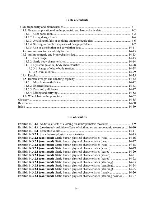
Table of contents14 <strong>Anthropometry</strong> <strong>and</strong> biomechanics........................................................................................ 14-1<strong>14.</strong>1 General application of anthropometric <strong>and</strong> biomechanic data .....................................14-2<strong>14.</strong>1.1 User population......................................................................................................14-2<strong>14.</strong>1.2 Using design limits ................................................................................................14-4<strong>14.</strong>1.3 Avoiding pitfalls in applying anthropometric data ................................................14-6<strong>14.</strong>1.4 Solving a complex sequence of design problems ..................................................14-7<strong>14.</strong>1.5 Use of distribution <strong>and</strong> correlation data...............................................................14-11<strong>14.</strong>2 Anthropometric variability factors..............................................................................14-13<strong>14.</strong>3 Anthropometric <strong>and</strong> biomechanics data......................................................................14-13<strong>14.</strong>3.1 Data usage............................................................................................................14-13<strong>14.</strong>3.2 Static body characteristics....................................................................................14-14<strong>14.</strong>3.3 Dynamic (mobile) body characteristics ...............................................................14-28<strong>14.</strong>3.3.1 Range of whole body motion........................................................................14-28<strong>14.</strong>3.3.2 Joint motion ..................................................................................................14-29<strong>14.</strong>4 Reach...........................................................................................................................14-35<strong>14.</strong>5 Human strength <strong>and</strong> h<strong>and</strong>ling capacity.......................................................................14-42<strong>14.</strong>5.1 Muscle strength factors........................................................................................14-42<strong>14.</strong>5.2 Exerted forces ......................................................................................................14-43<strong>14.</strong>5.3 Push <strong>and</strong> pull forces.............................................................................................14-47<strong>14.</strong>5.4 Lifting <strong>and</strong> carrying .............................................................................................14-52<strong>14.</strong>6 Wheelchair anthropometrics .......................................................................................14-52Glossary ................................................................................................................................... 14-55References................................................................................................................................ 14-58Index ........................................................................................................................................14-59List of exhibitsExhibit <strong>14.</strong>1.4.4 Additive effects of clothing on anthropometric measures ............................ 14-9Exhibit <strong>14.</strong>1.4.4 (continued) Additive effects of clothing on anthropometric measures..... 14-10Exhibit <strong>14.</strong>1.5.1 Percentile values..........................................................................................14-11Exhibit <strong>14.</strong>3.2.1 Static human physical characteristics..........................................................14-15Exhibit <strong>14.</strong>3.2.1 (continued) Static human physical characteristics (head)..........................14-16Exhibit <strong>14.</strong>3.2.1 (continued) Static human physical characteristics (head)..........................14-17Exhibit <strong>14.</strong>3.2.1 (continued) Static human physical characteristics (head)..........................14-18Exhibit <strong>14.</strong>3.2.1 (continued) Static human physical characteristics (seated) .......................14-19Exhibit <strong>14.</strong>3.2.1 (continued) Static human physical characteristics (seated) .......................14-20Exhibit <strong>14.</strong>3.2.1 (continued) Static human physical characteristics (seated) .......................14-21Exhibit <strong>14.</strong>3.2.1 (continued) Static human physical characteristics (seated) .......................14-22Exhibit <strong>14.</strong>3.2.1 (continued) Static human physical characteristics (st<strong>and</strong>ing)....................14-23Exhibit <strong>14.</strong>3.2.1 (continued) Static human physical characteristics (st<strong>and</strong>ing)....................14-24Exhibit <strong>14.</strong>3.2.1 (continued) Static human physical characteristics (st<strong>and</strong>ing)....................14-25Exhibit <strong>14.</strong>3.2.1 (continued) Static human physical characteristics (h<strong>and</strong>)..........................14-26Exhibit <strong>14.</strong>3.2.1 (continued) Static human physical characteristics (st<strong>and</strong>ing position)...... 14-2714-i
Exhibit <strong>14.</strong>3.3.2.1 Joint movement ranges.............................................................................14-30Exhibit <strong>14.</strong>3.3.2.1 (continued) Joint movement ranges .......................................................14-31Exhibit <strong>14.</strong>3.3.2.1 (continued) Joint movement ranges .......................................................14-32Exhibit <strong>14.</strong>3.3.2.2 Change in range of joint movement with movement in an adjacent joint 14-34Exhibit <strong>14.</strong>4.2 Reach envelopes in vertical <strong>and</strong> horizontal planes.........................................14-36Exhibit <strong>14.</strong>4.3 (a) Touch, grip, <strong>and</strong> grasp functions ..............................................................14-37Exhibit <strong>14.</strong>4.3 (a) (continued) Touch, grip, <strong>and</strong> grasp functions.........................................14-38Exhibit <strong>14.</strong>4.3 (b) Thumb <strong>and</strong> forefinger grasp boundary data for females in the 46 cm <strong>and</strong> 61cm horizontal planes ........................................................................................................14-39Exhibit <strong>14.</strong>4.3 (c) Thumb <strong>and</strong> forefinger grasp boundary data for females in the 0 <strong>and</strong> -15 cmvertical planes ..................................................................................................................14-40Exhibit <strong>14.</strong>5.2.1 Male muscle strength of the arm, h<strong>and</strong>, <strong>and</strong> thumb for control forces (5thpercentile values) .............................................................................................................14-44Exhibit <strong>14.</strong>5.2.1 (continued) Design criteria for male muscle strength of the arm, h<strong>and</strong>, <strong>and</strong>thumb for control forces (5th percentile values)..............................................................14-45Exhibit <strong>14.</strong>5.3.1 Horizontal push <strong>and</strong> pull forces that can be exerted ...................................14-47Exhibit <strong>14.</strong>5.3.2 Static muscle strength data for vertical pull exertions ................................14-49Exhibit <strong>14.</strong>5.3.2 (continued) Static muscle strength data for vertical pull exertions...........14-50Exhibit <strong>14.</strong>5.3.2 (continued) Static muscle strength data for vertical pull exertions...........14-51Exhibit <strong>14.</strong>6.1 Forward reach from a wheelchair...................................................................14-52Exhibit <strong>14.</strong>6.1 (continued) Forward reach from a wheelchair.............................................14-53Exhibit <strong>14.</strong>6.4 Side reach from a wheelchair.........................................................................14-53Exhibit <strong>14.</strong>6.6 Wheelchair dimensions. .................................................................................14-5414-ii
HFDS 2003 (amended Oct 2009)<strong>Chapter</strong> 14 <strong>Anthropometry</strong> <strong>and</strong> biomechanics14 <strong>Anthropometry</strong> <strong>and</strong> biomechanicsDesigners <strong>and</strong> human factors specialists incorporate scientificdata on human physical capabilities into the design of systems<strong>and</strong> equipment. Human physical characteristics, unlike those ofmachines, cannot be designed. However, failure to take intoaccount human physical characteristics when designing systemsor equipment can place unnecessary dem<strong>and</strong>s <strong>and</strong> restrictionsupon user personnel.Definitions. <strong>Anthropometry</strong> is the scientificmeasurement <strong>and</strong> collection of data about human physicalcharacteristics <strong>and</strong> the application (engineeringanthropometry) of these data in the design <strong>and</strong> evaluationof systems, equipment, manufactured products, humanmadeenvironments, <strong>and</strong> facilities. <strong>Biomechanics</strong>describes the mechanical characteristics of biologicalsystems, in this case the human body, in terms of physicalmeasures <strong>and</strong> mechanical models. This field isinterdisciplinary (mainly anthropometry, mechanics,physiology, <strong>and</strong> engineering). Its applications addressmechanical structure, strength, <strong>and</strong> mobility of humansfor engineering purposes.This chapter of the HFDS provides additional anthropometric<strong>and</strong> biomechanics data beyond that used in other chapters.Previous data are cross-referenced, where appropriate. Unlikethe other sections, this section provides more guidance about thenature of the data, its selection, <strong>and</strong> its proper use. It providesrules for applying the vast amount of human form data availableto specific design fit, function, <strong>and</strong> human task performance.The section also covers application principles <strong>and</strong> their resultingrules, human body measurement data (static <strong>and</strong> dynamic), rangeof motion <strong>and</strong> strength data, as well as comfort information.14-1
<strong>Chapter</strong> 14 <strong>Anthropometry</strong> <strong>and</strong> biomechanics HFDS 2003 (amended Oct 2009)<strong>14.</strong>1 General application of anthropometric <strong>and</strong> biomechanics data<strong>14.</strong>1.1 User populationIn this document, body size, strength, <strong>and</strong> mobility data arepresented. In the future, this population will include a widerrange of ethnic backgrounds <strong>and</strong> an increased number offemales. The average age is expected to decrease. These changeswill be important for future systems design.In this general section, design criteria <strong>and</strong> rules are given for: (1)ascertaining user population data, (2) using the design limitsapproach, (3) avoiding pitfalls in applying the data, (4) usingdistribution <strong>and</strong> correlation data, (5) solving design problems,<strong>and</strong> (6) using models.Anthropometric data are most appropriate when they are derivedfrom a survey of the existing worker population of interest. The<strong>FAA</strong> surveyed select static measurements from the TechnicalOperations worker population. These measurements arecompiled in Appendix B. Since the sub-population associatedwith the <strong>FAA</strong> has not been surveyed other than that contained inAppendix B, information from substitute sources is used as abasis for design for all other <strong>FAA</strong> populations <strong>and</strong>measurements.• <strong>14.</strong>1.1.1 Use of data. Anthropometric <strong>and</strong> biomechanics datashall be used in the design of systems, equipment (includingpersonal protection equipment), clothing, workplaces,passageways, controls, access openings, <strong>and</strong> tools. [Source:National Aeronautics <strong>and</strong> Space Administration (NASA-STD-3000A), 1989]Discussion. The human's interface with other systemcomponents needs to be treated as objectively <strong>and</strong>systematically as are other interface <strong>and</strong> hardwarecomponent designs. It is not acceptable to guess abouthuman physical characteristics or to use the designer'sown measurements or the measurements of associates.Application of appropriate anthropometric <strong>and</strong>biomechanics data is expected.14-2
HFDS 2003 (amended Oct 2009)<strong>Chapter</strong> 14 <strong>Anthropometry</strong> <strong>and</strong> biomechanics• <strong>14.</strong>1.1.2 Data to be used. Designers <strong>and</strong> human factorsspecialists shall use the anthropometric <strong>and</strong> biomechanics dataprovided in this document <strong>and</strong> the associated appendix. Ifadditional data are needed, they shall use the more complete datagiven in DOD-HDBK-743A. If other reference or new datacollections are considered, the contractor shall obtain theapproval of the acquisition program office. [Source: NASA-STD-3000A, 1989; Department of Defense (DOD-HDBK-743A), 1991]Discussion. If this document does not present dataneeded for the problem at h<strong>and</strong>, the designer will have toselect appropriate sample information from DOD-HDBK-743A. In that h<strong>and</strong>book, the 1988 military male <strong>and</strong>female survey distributions can be used to represent the<strong>FAA</strong> user population when needed, as it represents themost comprehensive samples available. Note that civilianworking populations could be expected to have a largerrange of sizes <strong>and</strong> ages than the military. Samples withcomprehensive measures are not available.• <strong>14.</strong>1.1.3 Using population extremes. Designers <strong>and</strong> humanfactors specialists shall draw upon the extremes of the largermale population distribution <strong>and</strong> the extremes of the smallerfemale population distributions to represent the upper <strong>and</strong> lowerrange values, respectively, to apply to anthropometric <strong>and</strong>biomechanics design problems. [Source: NASA-STD-3000A, 1989]Discussion. The use of separate male <strong>and</strong> femalepopulation data is a conservative approach that results inmore inclusive design dimensions than the samepercentiles would from a composite population.14-3
<strong>Chapter</strong> 14 <strong>Anthropometry</strong> <strong>and</strong> biomechanics HFDS 2003 (amended Oct 2009)<strong>14.</strong>1.2 Using design limitsInitial rules in this section address the design limits approach.To underst<strong>and</strong> this approach, it is helpful to consider the overallsteps <strong>and</strong> choices that one makes in applying anthropometric <strong>and</strong>biomechanics data. The design limits approach entails selectingthe most appropriate percentile values in population distributions<strong>and</strong> applying the appropriate associated data in a design solution.These steps are listed in this introductory material <strong>and</strong> areexplained in detail in the initial three rules of this subsection. Ifthe reader has applied the design limit approach <strong>and</strong> underst<strong>and</strong>sit, the reader can skip the rest of this introductory material aswell as the explanations associated with the first three rules.However the reader should not skip the rules.Definition. The design limits approach is a method ofapplying population or sample statistics <strong>and</strong> data abouthuman physical characteristics to a design so that adesired portion of the user population is accommodatedby the design. The range of users accommodated is afunction of limits used in setting the population portion.To underst<strong>and</strong> the design limits approach, it is helpful toconsider step by step the choices that design personnel make inapplying these human physical data.a. Select the correct human physical characteristic <strong>and</strong> itsapplicable measurement characteristic (description) forthe design problem at h<strong>and</strong>.b. Select the appropriate population, representative sample,or rule information on the selected human physicalcharacteristic <strong>and</strong> measurement description to apply tothe design problem.c. Determine the appropriate statistical point(s), usuallypercentile points from rule information or from thesample distribution(s) in order to accommodate a desiredrange of the human characteristic within the distributionof the user population.d. Read directly or determine statistically the measurementvalue(s) that corresponds to the selected statisticalpoint(s) relevant to the population distribution.e. Incorporate the measurement value as a criterion for thedesign dimension, or in the case of biomechanics data, forthe movement or force solution in the design problem.14-4
HFDS 2003 (amended Oct 2009)<strong>Chapter</strong> 14 <strong>Anthropometry</strong> <strong>and</strong> biomechanics• <strong>14.</strong>1.3.3 Summation of segment dimensions. Summation of likepercentile values for body components shall not be used torepresent any human physical characteristic that appears to be acomposite of component characteristics. [Source: NASA-STD-3000A, 1989]Discussion. The 95th percentile arm length, for instance,is not the addition of the 95th percentile shoulder-toelbowlength plus the 95th percentile elbow-to-h<strong>and</strong>length. The actual 95th percentile arm length will besomewhat less than the erroneous summation. Todetermine the 95th percentile arm length, one must use adistribution of arm length rather than component partdistributions.<strong>14.</strong>1.4 Solving a complex sequence of design problemsIn this section, rules are presented for approaching complexdesign problems that require the consideration of a sequence ofrelevant design reference locations (such as seat reference points<strong>and</strong> eye reference zones), human physical characteristics,statistical points, <strong>and</strong> measures. The recommended approachinvolves identifying the necessary human activities <strong>and</strong> positions<strong>and</strong> establishing reference points <strong>and</strong> envelopes for the necessaryactivities. These envelopes impact the location <strong>and</strong> design ofcontrols <strong>and</strong> displays, as well as the placement of work surfaces,equipment, <strong>and</strong> seating accommodations. The effects of clothingor carried equipment are then used to exp<strong>and</strong> the dimensions.• <strong>14.</strong>1.4.1 Design to body positions <strong>and</strong> motions of the tasks.Design personnel shall base the necessary operator <strong>and</strong> user bodypositions <strong>and</strong> motions on personnel tasks to be performed duringnormal, degraded, <strong>and</strong> emergency modes of operations <strong>and</strong>maintenance. [Source: NASA-STD-3000A, 1989]14-7
<strong>Chapter</strong> 14 <strong>Anthropometry</strong> <strong>and</strong> biomechanics HFDS 2003 (amended Oct 2009)• <strong>14.</strong>1.4.2 Construction or collection of unique position data. Ifthe common <strong>and</strong> mobile working positions data in <strong>Chapter</strong> 10 ofthis document do not represent the unique working positionsassociated with a design, then design personnel shall constructthe applicable human physical characteristics <strong>and</strong> measures fromthe static <strong>and</strong> dynamic data provided later in Sections <strong>14.</strong>3.2 <strong>and</strong><strong>14.</strong>3.3 or in DOD-HDBK-743A. If no applicable data can befound or calculated for important design measures, then, with theprior approval of the acquisition program office, samplemeasures shall be taken on appropriate personnel for the uniqueworking positions. [Source: DOD-HDBK-743A, 1991; Roebuck,Kroemer, & Thomson, 1975]Discussion. Anthropometric measurement needs to bedone by professionals because there are manycomplexities <strong>and</strong> potential interactions among positionsof body segments, as well as many technical points <strong>and</strong>pitfalls to avoid in measurement practice. Samplemeasurement methods can be found in Roebuck,Kroemer, <strong>and</strong> Thomson, 1975. <strong>14.</strong>1.4.3 Building <strong>and</strong> using reach envelopes. If reach dataprovided in this document (see Section <strong>14.</strong>4) do not apply to aspecific design problem, then reach design dimensions orenvelopes for design use should be constructed considering:a. one-h<strong>and</strong>ed or two-h<strong>and</strong>ed operation,b. grasp requirements which may affect the functional reachenvelope,c. positional relationship of a shoulder reference point orarm rotation point to the seat back, seat reference point,or other posture reference or design reference points, <strong>and</strong>d. the appropriate samples <strong>and</strong> anthropometricmeasurements from the data provided in this document orin DOD-HDBK-743A, 1991 (see Paragraph <strong>14.</strong>1.1.2).[Source: DOD-HDBK-743A, 1991]14-8
HFDS 2003 (amended Oct 2009)<strong>Chapter</strong> 14 <strong>Anthropometry</strong> <strong>and</strong> biomechanics• <strong>14.</strong>1.4.4 Effects of clothing. Because most anthropometric datapresented in this document <strong>and</strong> in other data sources representnude body measurements (unless otherwise indicated), suitableallowances shall be made for light, medium, or heavy clothing<strong>and</strong> for any special protective equipment that is worn. Note thatmeasurements of <strong>FAA</strong> Technical Operations Personnel containedin Appendix B represent clothed body measurements. Exhibit<strong>14.</strong>1.4.4 illustrates the additive effects of clothing on static bodydimensions <strong>and</strong> shows the 95th percentile gloved h<strong>and</strong> measures.If special items of protective clothing or equipment are involved,the effects shall be measured in positions required by the users'tasks. The effects on the extremes of the population distributionshall be determined. [Source: Department of Defense (MIL-HDBK-759B), 1992; Johnson, 1984]Discussion. Nude dimension <strong>and</strong> light clothing can beregarded as synonymous for practical purposes.Additional information on the changes in anthropometricmeasurement values imposed by different clothingensembles is found in Johnson, 1984.Exhibit <strong>14.</strong>1.4.4 Additive effects of clothing on anthropometric measures14-9
<strong>Chapter</strong> 14 <strong>Anthropometry</strong> <strong>and</strong> biomechanics HFDS 2003 (amended Oct 2009)Exhibit <strong>14.</strong>1.4.4 (continued) Additive effects of clothing on anthropometric measuresA B CAnti-contact Wet-cold Arcticglove glove gloveH<strong>and</strong> position X Y Z X Y Z X Y ZExtended flat cm 26.7 11.9 6.4 27.2 <strong>14.</strong>5 7.6 42.2 13.7 9.1(in) (10.5) (4.7) (2.5) (10.7) (5.7) (3.0) (16.6) (5.4) (3.6)Closed as fist cm 17.8 12.7 8.4 18.5 <strong>14.</strong>7 9.4 36.3 13.2 13.7(in) (7.0) (5.0) (3.3) (7.3) (5.8) (3.7) (<strong>14.</strong>3) (5.2) (5.4)Grasping h<strong>and</strong>le0.6 cm (0.24 in) 17.8 12.7 8.9 18.5 <strong>14.</strong>0 8.9 35.6 <strong>14.</strong>0 11.4diameter (7.0) (5.0) (3.5) (7.3) (5.5) (3.5) (<strong>14.</strong>0) (5.5) (4.5)2.5 cm (1.0 in) 17.8 12.7 8.9 18.5 13.5 10.2 35.6 13.2 11.4diameter (7.0) (5.0) (3.5) (7.3) (5.3) (4.0) (<strong>14.</strong>0) (5.2) (4.5)5.0 cm (2.0 in) 19.0 11.4 10.7 20.3 11.9 10.2 38.1 13.7 12.7diameter (7.5) (4.5) (4.2) (8.0) (4.7) (4.0) (15.0) (5.4) (5.0)Grasping knob0.6 cm (0.24 in) 20.3 9.7 10.9 22.9 11.7 10.2 39.4 12.2 11.4diameter (8.0) (3.8) (4.3) (9.0) (4.6) (4.0) (15.5) (4.8) (4.5)2.5 cm (1.0 in) 22.8 8.9 10.2 22.9 11.4 10.2 40.1 12.2 12.2diameter (9.0) (3.5) (4.0) (9.0) (4.5) (4.0) (15.8) (4.8) (4.8)5.0 cm (2.0 in) 24.1 9.4 9.4 23.4 11.4 10.7 40.5 11.9 12.2diameter (9.5) (3.7) (3.7) (9.2) (4.5) (4.1) (15.9) (4.7) (4.8)14-10
HFDS 2003 (amended Oct 2009)<strong>Chapter</strong> 14 <strong>Anthropometry</strong> <strong>and</strong> biomechanics<strong>14.</strong>1.5 Use of distribution <strong>and</strong> correlation dataComplex uses of statistical data concerning human physicaldimensions or capabilities are introduced in this section. Data<strong>and</strong> distribution information on a single physical characteristic<strong>and</strong> its measures provides no information about thatcharacteristic's composite relationship with any othercharacteristic <strong>and</strong> its measures. For design, the relationshipbetween two or more characteristics <strong>and</strong> how their measures varytogether is important. Consider sizing clothing <strong>and</strong> designingseats. Bivariate distributions <strong>and</strong> correlation statistics can beused by knowledgeable professionals to determine designcriteria. <strong>14.</strong>1.5.1 Gaussian distribution of measurement values on asingle human physical characteristic. The relationshipbetween the Gaussian distribution <strong>and</strong> the measurement valueequivalent to the desired percentile statistic value should best bedetermined from a smoothed frequency distribution or from theformula presented in Exhibit <strong>14.</strong>1.5.1 if the following conditionsare met:a. the percentile value is not given in applicable Humanmachine-interfacedata, <strong>and</strong>b. the population distribution for the applicable humanphysical characteristic is known to be Gaussian (normal)<strong>and</strong> the mean <strong>and</strong> variance are known. [Source: Israelski,1977]Exhibit <strong>14.</strong>1.5.1 Percentile values14-11
<strong>Chapter</strong> 14 <strong>Anthropometry</strong> <strong>and</strong> biomechanics HFDS 2003 (amended Oct 2009) <strong>14.</strong>1.5.2 Using bivariate distribution data. Bivariate datashould be professionally applied <strong>and</strong> interpreted since knowledgeof the population distribution characteristics are necessary toproject <strong>and</strong> extract design limits <strong>and</strong> to apply them to designproblems. [Source: MIL-HDBK-759B, 1992]Discussion. The variability of two body measurements<strong>and</strong> their interrelationship with each other may bepresented in a graph or a table. Bivariate informationincludes the ranges of two measurements <strong>and</strong> thepercentages or frequencies of individuals who arecharacterized by the various possible combinations ofvalues of the two measurements. Knowledgeableprofessionals can tell about the relationships from theappearance <strong>and</strong> shape of the joint distribution ofmeasures. Correlation statistics, when the relationshipwarrants, provide additional insight, <strong>and</strong> whenappropriate samples are large enough, may providepredictions of population values. <strong>14.</strong>1.5.3 Use of correlation <strong>and</strong> multiple correlation data.When two or more human physical characteristics are applicableto a design problem, professionals should apply <strong>and</strong> interpretcorrelation statistics. Knowledge about distributions <strong>and</strong>intercorrelations among the distributions need to be factored intothe use of these data. [Source: MIL-HDBK-759B, 1992; Kroemer,Kroemer, & Kroemer-Elbert 1990]Discussion. The relationships or correlations betweenspecific body measurements are highly variable amongthe various human characteristics <strong>and</strong> may differ acrosssamples <strong>and</strong> populations. For example, breadthmeasurements tend to be more highly correlated withweight than with stature. The degree of the relationshipmay be expressed by a correlation coefficient or "r"value.Although common percentile values may not be used tosum data across adjacent body parts, (see Paragraph<strong>14.</strong>1.3.3), regression equations derived from theapplicable samples can be used in constructing compositebody measures.Definition. The correlation coefficient or "r" valuedescribes the degree to which two variables vary together(positive correlation) or vary inversely (negativecorrelation). The correlation coefficient, "r", has a rangeof values from +1.0 (perfect positive correlation) through-1.0 (perfect negative correlation). Multiple correlationinvolves the predictable relationship of two or morevariables with another criterion variable (such as acomposite measurement value). "R" is the multiplecorrelation coefficient. It is recommended that onlycorrelations with strong predictive values be used (that iswhere r or R is at least or greater than |.7|). (Note: R 2 isthe square of the multiple correlation coefficient <strong>and</strong>equates to the proportion of the variation accounted for in14-12
HFDS 2003 (amended Oct 2009)<strong>Chapter</strong> 14 <strong>Anthropometry</strong> <strong>and</strong> biomechanics<strong>14.</strong>2 Anthropometric variability factorsthe prediction. An R of .7 would account for about 50percent of the variation).There are many factors that relate to the large variabilityobserved in measures of the human body. These factors include:(1) body position, (2) age, health, <strong>and</strong> body condition, (3) sex,(4) race <strong>and</strong> national origin, (5) occupation, <strong>and</strong> (6) evolutionarytrends. These factors affect future population sampling <strong>and</strong>encourage the use of the most recent data on the populations ofinterest. If designers <strong>and</strong> human factors specialists need to drawupon other data or accomplish some special purpose sampling,the following rules related to data variability may assist. <strong>14.</strong>2.1 Foreign populations. If a specific use of the system orequipment involves operation or maintenance by foreignpersonnel in locations outside the United States, sample datashould be obtained that represents the foreign work force.[Source: Israelski, 1977] <strong>14.</strong>2.2 Body slump. In determining body position <strong>and</strong> eyeposition zones for seated or st<strong>and</strong>ing positions, a slump factorwhich accompanies relaxation should be taken into account.Seated-eye height measurements can be reduced by as much as65 mm (2.56 in) when a person sits in a relaxed position. Bodyslump, when st<strong>and</strong>ing, reduces stature as much as 19 mm (.75 in)from a perfectly erect position. These slump factors should beconsidered in designing adjustable seats, visual envelopes, <strong>and</strong>display locations. [Source: Israelski, 1977]<strong>14.</strong>3 Anthropometric <strong>and</strong> biomechanics data<strong>14.</strong>3.1 Data usageThis section provides general guidance for the use of specificanthropometric <strong>and</strong> biomechanics data, static bodycharacteristics data, dynamic body characteristic data, includingrange of joint motion <strong>and</strong> common <strong>and</strong> mobile workingpositions.Dimensions of the human body which influence the design ofpersonal <strong>and</strong> operational equipment are of two types: (1) staticdimensions, which are measurements of the head, torso, <strong>and</strong>limbs in normal positions, <strong>and</strong> (2) dynamic dimensions, whichare measurements taken in working positions or duringmovement. [Source: AFSC DH 1-3, 1980; NASA-STD-3000A, 1989]• <strong>14.</strong>3.1.1 Use of anthropometric <strong>and</strong> biomechanics data. Datathroughout Section <strong>14.</strong>3 <strong>and</strong> the associated appendix are to beused for anthropometric issues that are not addressed in earliersections of this document. If designers <strong>and</strong> human factorsspecialists need additional data to solve anthropometric designproblems associated with human physical characteristics, they14-13
<strong>Chapter</strong> 14 <strong>Anthropometry</strong> <strong>and</strong> biomechanics HFDS 2003 (amended Oct 2009)<strong>14.</strong>3.2 Static body characteristicsshall use the data presented in DOD-HDBK-743A (see also<strong>14.</strong>1.1.2). [Source: DOD-HDBK-743A, 1991]• <strong>14.</strong>3.1.2 Task considerations. Designers <strong>and</strong> human factorsspecialists shall take the following task conditions intoconsideration when using the human physical characteristic datapresented in this section:a. the nature, frequency, <strong>and</strong> difficulty of the related tasks tobe performed by the operator or user of the equipment,b. the position of the body during performance of operations<strong>and</strong> maintenance tasks,c. mobility <strong>and</strong> flexibility dem<strong>and</strong>s imposed by maintenancetasks,d. the touch, grasp, torque, lift, <strong>and</strong> carry requirements ofthe tasks,e. increments in the design-critical dimensions imposed byclothing or equipment, packages, <strong>and</strong> tools, <strong>and</strong>f. increments in the design-critical dimensions imposed bythe need to compensate for obstacles <strong>and</strong> projections.[Source: MIL-HDBK-759B, 1992; MIL-STD-1472D, 1989] <strong>14.</strong>3.2.1 Static data. Exhibit <strong>14.</strong>3.2.1 presents static humanphysical characteristics <strong>and</strong> measurement values which should beused, as applicable, in design problems. Exhibit <strong>14.</strong>3.2.1addresses the following body parts: head, seated body, st<strong>and</strong>ingbody, <strong>and</strong> h<strong>and</strong>s. [Source: DOD-HDBK-743A, 1991] <strong>14.</strong>3.2.2 Static data for Technical Operations Personnel.Appendix B presents static human physical characteristics <strong>and</strong>measurement values that should be used, as applicable, in thedesign of equipment to be used by Technical Operationspersonnel. [Source: Bradtmiller, B., Hodge, B., Kristensen, S., & Mucher,M., 2008]14-14
HFDS 2003 (amended Oct 2009)<strong>Chapter</strong> 14 <strong>Anthropometry</strong> <strong>and</strong> biomechanicsExhibit <strong>14.</strong>3.2.1 Static human physical characteristics1 Head Breadth. The maximum breadth of the head, usually above <strong>and</strong>behind the ears.PercentilesSample 1st 5th 50th 95th 99thA Men cm 13.9 <strong>14.</strong>3 15.2 16.1 16.5(in) (5.5) (5.6) (6.0) (6.3) (6.5)B Women cm 13.3 13.7 <strong>14.</strong>4 15.3 15.7(in) (5.2) (5.4) (5.7) (6.0) (6.2)2 Interpupillary Breadth. The distance between the centers of thepupils of the eyes (as the eyes are looking straight ahead).PercentilesSample 1st 5th 50th 95th 99thA Men cm 5.7 5.9 6.5 7.1 7.4(in) (2.2) (2.3) (2.6) (2.8) (2.9)B Women cm 5.5 5.7 6.2 6.9 7.1(in) (2.2) (2.2) (2.4) (2.7) (2.8)3 Face Breadth (bizygomatic). The breadth of the face, measuredacross the most lateral projections of the cheek bones (zygomaticarches).PercentilesSample 1st 5th 50th 95th 99thA Men cm 12.8 13.2 <strong>14.</strong>0 15.0 15.4(in) (5.0) (5.2) (5.5) (5.9) (6.1)B Women cm 12.1 12.3 13.1 <strong>14.</strong>0 <strong>14.</strong>4(in) (4.8) (4.8) (5.2) (5.5) (5.7)4 Face Length (menton-sellion). The vertical distance from the tip ofthe chin (menton) to the deepest point on the nasal root depressionbetween the eyes (sellion).PercentilesSample 1st 5th 50th 95th 99thA Men cm 10.8 11.2 12.2 13.3 13.7(in) (4.3) (4.4) (4.8) (5.2) (5.4)B Women cm 10.1 10.4 11.3 12.4 12.9(in) (4.0) (4.1) (4.4) (4.9) (5.1)14-15
<strong>Chapter</strong> 14 <strong>Anthropometry</strong> <strong>and</strong> biomechanics HFDS 2003 (amended Oct 2009)Exhibit <strong>14.</strong>3.2.1 (continued) Static human physical characteristics (head)5 Biocular Breadth. The distance from the outer corners of the eyes(right <strong>and</strong> left ectocanthi).PercentilesSample 1st 5th 50th 95th 99thA Men cm 11.0 11.3 12.2 13.1 13.6(in) (4.3) (4.4) (4.8) (5.2) (5.4)B Women cm 10.8 11.1 11.6 12.9 13.3(in) (4.3) (4.4) (4.6) (5.1) (5.2)6 Bitragion Breadth. The breadth of the head from the right tragion tothe left. (Tragion is the cartilaginous notch at the front of the ear).PercentilesSample 1st 5th 50th 95th 99thA Men cm 13.1 13.5 <strong>14.</strong>5 15.5 15.9(in) (5.2) (5.3) (5.7) (6.1) (6.3)B Women cm 12.5 12.8 13.3 <strong>14.</strong>3 15.0(in) (4.9) (5.0) (5.2) (5.6) (5.9)7 Glabella to Back of Head. The horizontal distance from the mostanterior point of the forehead between the brow-ridges (glabella) tothe back of the head, measured with a headboard.PercentilesSample 1st 5th 50th 95th 99thA Men cm 18.3 18.8 20.0 21.1 21.7(in) (7.2) (7.4) (7.9) (8.3) (8.5)B Women cm 17.5 18.0 19.1 20.2 20.7(in) (6.9) (7.1) (7.5) (8.0) (8.1)8 Menton to Back of Head. The horizontal distance from the tip of thechin (menton) to the back of the head, measured with a headboard.PercentilesSample 1st 5th 50th 95th 99thA Men cm 15.7 16.5 18.2 20.0 20.7(in) (6.2) (6.5) (7.2) (7.9) (8.1)B Women cm 15.2 15.8 17.3 18.9 19.6(in) (6.0) (6.2) (6.8) (7.4) (7.7)14-16
HFDS 2003 (amended Oct 2009)<strong>Chapter</strong> 14 <strong>Anthropometry</strong> <strong>and</strong> biomechanicsExhibit <strong>14.</strong>3.2.1 (continued) Static human physical characteristics (head)9 Sellion to Top of Head. The vertical distance from the nasal rootdepression between the eyes (sellion) to the level of the top of the head,measured with a headboard.PercentilesSample 1st 5th 50th 95th 99thA Men cm 9.7 10.1 11.2 12.4 12.9(in) (3.8) (4.0) (4.4) (4.9) (5.1)B Women cm 9.0 9.5 10.5 11.7 12.2(in) (3.5) (3.7) (4.1) (4.6) (4.8)10 Stomion to Top of Head. The vertical distance from the midpoint ofthe lips (stomion) to the level of the top of the head, measured with aheadboard.PercentilesSample 1st 5th 50th 95th 99thA Men cm 16.9 17.4 18.6 19.9 20.6(in) (6.7) (6.9) (7.3) (7.8) (8.1)B Women cm 15.7 16.3 17.5 18.8 19.4(in) (6.2) (6.4) (6.9) (7.4) (7.6)11 Sellion to Back of Head. The horizontal distance from the nasal rootdepression between the eyes (sellion) to the back of the head, measuredwith a headboard.PercentilesSample 1st 5th 50th 95th 99thA Men cm 18.0 18.5 19.7 20.9 21.4(in) (7.1) (7.3) (7.8) (8.2) (8.4)B Women cm 17.4 17.8 18.9 20.0 20.5(in) (6.9) (7.0) (7.4) (7.9) (8.1)12 Pronasale to Back of Head. The horizontal distance from the tip ofthe nose (pronasale) to the back of the head, measured with aheadboard.PercentilesSample 1st 5th 50th 95th 99thA Men cm 20.0 20.5 22.0 23.2 23.9(in) (7.9) (8.1) (8.7) (9.1) (9.4)B Women cm 19.2 19.7 21.0 22.2 22.8(in) (7.6) (7.8) (8.3) (8.7) (9.0)14-17
<strong>Chapter</strong> 14 <strong>Anthropometry</strong> <strong>and</strong> biomechanics HFDS 2003 (amended Oct 2009)Exhibit <strong>14.</strong>3.2.1 (continued) Static human physical characteristics (head)13 Head Length. The maximum length of the head; measured from themost anterior point of the forehead between the brow-ridges (glabella)to the back of the head (occiput).PercentilesSample 1st 5th 50th 95th 99thA Men cm 18.0 18.5 19.7 20.9 21.3(in) (7.1) (7.3) (7.8) (8.2) (8.4)B Women cm 17.2 17.6 18.7 19.8 20.2(in) (6.8) (6.9) (7.4) (7.8) (8.0)14 Menton to Top of Head. The vertical distance from the tip of the chin(menton) to the level of the top of the head, measured with aheadboard.PercentilesSample 1st 5th 50th 95th 99thA Men cm 21.2 21.8 23.2 24.7 25.5(in) (8.3) (8.6) (9.1) (9.7) (10.0)B Women cm 19.8 20.4 21.8 23.2 23.8(in) (7.8) (8.0) (8.6) (9.1) (9.4)15 Menton-crinion Length. The vertical distance from the bottom of thechin (menton) to the midpoint of the hairline (crinion).PercentilesSample 1st 5th 50th 95th 99thA Men cm 16.6 17.4 19.1 20.9 21.6(in) (6.5) (6.9) (7.5) (8.2) (8.5)B Women cm 15.5 16.1 17.7 19.2 19.9(in) (6.1) (6.3) (7.0) (7.6) (7.8)16 Menton-subnasale Length. The distance from the bottom of the chin(menton) to the base of the nasal septum (subnasale).PercentilesSample 1st 5th 50th 95th 99thMen cm 6.1 6.5 7.3 8.3 8.7(in) (2.4) (2.6) (2.9) (3.3) (3.4)Women cm 5.7 6.0 6.9 7.8 8.3(in) (2.2) (2.4) (2.7) (3.1) (3.3)14-18
HFDS 2003 (amended Oct 2009)<strong>Chapter</strong> 14 <strong>Anthropometry</strong> <strong>and</strong> biomechanicsExhibit <strong>14.</strong>3.2.1 (continued) Static human physical characteristics (seated)17 Shoulder Length. The surface distance along the top of the shoulderfrom the junction of the neck <strong>and</strong> shoulder to the point of the shoulder(acromion).PercentilesSample 1st 5th 50th 95th 99thA Men cm 12.4 13.3 15.0 16.9 17.7(in) (4.9) (5.2) (5.9) (6.7) (7.0)B Women cm 12.0 12.7 <strong>14.</strong>5 16.2 17.1(in) (4.7) (5.0) (5.7) (6.4) (6.7)18 Mid-shoulder Height, Sitting. The vertical distance from the sittingsurface of the shoulder halfway between the neck <strong>and</strong> the point of theshoulder, measured with the subject sitting.PercentilesSample 1st 5th 50th 95th 99thA Men cm 56.3 58.3 63.0 67.7 69.4(in) (22.2) (23.0) (24.8) (26.7) (27.3)B Women cm 52.3 53.9 58.4 63.1 64.7(in) (20.6) (21.2) (23.0) (24.8) (25.5)19 Trunk (Suprasternale) Height, Sitting. The vertical distance fromthe sitting surface to the lowest point of the notch in the upper edge ofthe breast bone (suprasternale), measured with the subject sitting.PercentilesSample 1st 5th 50th 95th 99thA Men cm 53.1 55.2 59.6 64.2 65.9(in) (20.9) (21.7) (23.5) (25.3) (25.9)B Women cm 49.8 51.1 55.3 59.6 61.2(in) (19.6) (20.1) (21.8) (23.5) (24.1)20 Waist Height, Sitting. The vertical distance from the sitting surfaceto the level of the waist (natural indentation), measured with thesubject sitting.PercentilesSample 1st 5th 50th 95th 99thA Men cm 24.8 26.0 28.7 31.5 32.9(in) (9.8) (10.2) (11.3) (12.4) (13.0)B Women cm 22.8 24.4 28.0 31.5 32.7(in) (9.0) (9.6) (11.0) (12.4) (12.9)14-19
<strong>Chapter</strong> 14 <strong>Anthropometry</strong> <strong>and</strong> biomechanics HFDS 2003 (amended Oct 2009)Exhibit <strong>14.</strong>3.2.1 (continued) Static human physical characteristics (seated)21 Sitting Height. The vertical distance from the sitting surface to the topof the head, measured with the subject sitting. ** For TechnicalOperations Specialists, use # 17 in Appendix B.PercentilesSample 1st 5th 50th 95th 99thA Men cm 82.2 85.5 91.4 97.2 99.1(in) (32.4) (33.7) (36.0) (38.3) (39.0)B Women cm 77.5 79.5 85.1 91.0 93.3(in) (30.5) (31.3) (33.5) (35.8) (36.7)22 Shoulder (Acromiale) Height, Sitting. The vertical distance from thesitting surface to the point of the shoulder (acromion), measured withthe subject sitting.PercentilesSample 1st 5th 50th 95th 99thA Men cm 52.2 54.9 59.8 64.6 66.5(in) (20.6) (21.6) (23.5) (25.4) (26.2)B Women cm 49.2 50.9 55.5 60.4 62.3(in) (19.4) (20.0) (21.9) (23.8) (24.5)23 Elbow-grip Length. The horizontal distance from the back of theelbow to the center of the clenched fist. **For Technical OperationsSpecialists, use # 10 in Appendix B.PercentilesSample 1st 5th 50th 95th 99thA Men cm 32.3 33.2 35.9 39.1 40.3(in) (12.7) (13.1) (<strong>14.</strong>1) (15.4) (15.9)B Women cm 28.9 30.0 32.8 35.8 37.2(in) (11.4) (11.8) (12.9) (<strong>14.</strong>1) (<strong>14.</strong>6)24 Elbow Rest Height. The vertical distance from the sitting surface tothe bottom of the tip of the elbow, measured with the subject sitting <strong>and</strong>the forearm held horizontally. **For Technical Operations Specialists,use # 19 in Appendix B.PercentilesSample 1st 5th 50th 95th 99thA Men cm 16.8 18.4 23.2 27.4 29.2(in) (6.6) (7.2) (9.1) (10.8) (11.5)B Women cm 15.8 17.6 22.1 26.4 28.2(in) (6.2) (6.9) (8.7) (10.4) (11.1)14-20
HFDS 2003 (amended Oct 2009)<strong>Chapter</strong> 14 <strong>Anthropometry</strong> <strong>and</strong> biomechanicsExhibit <strong>14.</strong>3.2.1 (continued) Static human physical characteristics (seated)25 Eye Height, Sitting. The vertical distance from the sitting surface tothe outer corner of the eye (ectocanthus), measured with the subjectsitting. **For Technical Operations Specialists, use # 18 in AppendixB.PercentilesSample 1st 5th 50th 95th 99thA Men cm 71.2 73.5 79.2 84.8 86.9(in) (28.0) (28.9) (31.2) (33.4) (34.2)B Women cm 66.4 68.5 73.8 79.4 81.6(in) (26.1) (27.0) (29.1) (31.3) (32.1)26 Thigh Clearance. The vertical distance from the sitting surface to thehighest point of the thigh, measured with the subject sitting. **ForTechnical Operations Specialists, use # 21 in Appendix B.PercentilesSample 1st 5th 50th 95th 99thA Men cm <strong>14.</strong>1 <strong>14.</strong>9 16.8 19.0 20.1(in) (5.6) (5.9) (6.6) (7.5) (7.9)B Women cm 13.4 <strong>14.</strong>0 15.8 18.0 19.0(in) (5.3) (5.5) (6.2) (7.1) (7.5)27 Elbow-Fingertip Length. The horizontal distance from the back ofthe elbow to the tip of the middle finger, with the h<strong>and</strong> extended. **ForTechnical Operations Specialists, use # 9 in Appendix B.PercentilesSample 1st 5th 50th 95th 99thA Men cm 43.4 44.8 48.3 52.4 54.2(in) (17.1) (17.6) (19.0) (20.6) (21.3)B Women cm 39.1 40.6 44.2 48.3 49.8(in) (15.4) (16.0) (17.4) (19.0) (19.6)28 Knee Height, Sitting. The vertical distance from the footrest surfaceto the top of the knee, measured with the subject sitting. **ForTechnical Operations Specialists, use # 22 in Appendix B.PercentilesSample 1st 5th 50th 95th 99thA Men cm 49.7 51.4 55.8 60.6 62.3(in) (19.6) (20.2) (22.0) (23.9) (24.5)B Women cm 45.5 47.4 51.4 56.0 57.8(in) (17.9) (18.7) (20.2) (22.0) (22.8)14-21
<strong>Chapter</strong> 14 <strong>Anthropometry</strong> <strong>and</strong> biomechanics HFDS 2003 (amended Oct 2009)Exhibit <strong>14.</strong>3.2.1 (continued) Static human physical characteristics (seated)29 Vertical Reach, Sitting. The vertical distance from the sitting surfaceto the tip of the middle finger, measured with the subject sitting <strong>and</strong>the arm, h<strong>and</strong>, <strong>and</strong> fingers extended vertically.PercentilesSample 1st 5th 50th 95th 99thA Men cm 129.3 133.8 143.3 153.2 156.7(in) (50.9) (52.7) (56.4) (60.3) (61.7)B Women cm 119.7 123.3 132.7 141.8 145.4(in) (47.1) (48.5) (52.2) (55.8) (57.2)30 Abdominal Depth, Sitting. The depth of the abdomen, with thesubject sitting.PercentilesSample 1st 5th 50th 95th 99thA Men cm 18.6 19.9 23.6 29.1 31.4(in) (7.3) (7.8) (9.3) (11.5) (12.4)B Women cm 17.3 18.5 21.9 27.1 29.5(in) (6.8) (7.3) (8.6) (10.7) (11.6)31 Popliteal Height, Sitting. The vertical distance from the footrestsurface to the underside of the lower leg, measured with the subjectsitting.PercentilesSample 1st 5th 50th 95th 99thA Men cm 37.8 39.5 43.3 47.6 49.5(in) (<strong>14.</strong>9) (15.6) (17.0) (18.7) (19.5)B Women cm 33.7 35.1 38.9 42.9 44.6(in) (13.3) (13.8) (15.3) (16.9) (17.6)32 Forearm-Forearm Breadth, Sitting. The horizontal distance acrossthe body between the outer surfaces of the forearms, measured withthe forearms flexed <strong>and</strong> held against the body.PercentilesSample 1st 5th 50th 95th 99thA Men cm 45.1 47.7 54.5 62.1 65.3(in) (17.8) (18.8) (21.5) (24.4) (25.7)B Women cm 39.4 41.5 46.7 52.8 56.0(in) (15.5) (16.3) (18.4) (20.8) (22.0)14-22
HFDS 2003 (amended Oct 2009)<strong>Chapter</strong> 14 <strong>Anthropometry</strong> <strong>and</strong> biomechanicsExhibit <strong>14.</strong>3.2.1 (continued) Static human physical characteristics (st<strong>and</strong>ing)33 Shoulder (Bideltoid) Breadth. The horizontal distance across theupper arms between the maximum bulges of the deltoid muscles; thearms are hanging <strong>and</strong> relaxed.PercentilesSample 1st 5th 50th 95th 99thA Men cm 43.4 45.0 49.1 53.5 55.2(in) (17.1) (17.7) (19.3) (21.2) (21.7)B Women cm 38.0 39.7 43.1 47.2 49.2(in) (15.0) (15.6) (17.0) (18.6) (19.4)34 Stature. The vertical distance from the floor to the top of the head.**For Technical Operations Specialists, use # 5 in Appendix B.PercentilesSample 1st 5th 50th 95th 99thA Men cm 160.3 164.7 175.5 186.7 190.9(in) (63.1) (64.8) (69.1) (73.5) (75.2)B Women cm 148.3 152.8 162.7 173.7 178.0(in) (58.4) (60.2) (64.1) (68.4) (70.1)35 Suprasternale Height. The vertical distance from the floor to thelowest point of the notch in the upper edge of the breast bone(suprasternale).PercentilesSample 1st 5th 50th 95th 99thA Men cm 130.2 134.3 143.7 153.7 157.5(in) (51.3) (52.9) (56.6) (60.5) (62.0)B Women cm 120.7 124.1 132.9 142.5 146.4(in) (47.5) (48.9) (52.3) (56.1) (57.6)36 Tragion Height, St<strong>and</strong>ing. The vertical distance from the floor to thetragion, the cartilaginous notch at the front of the ear.PercentilesSample 1st 5th 50th 95th 99thA Men cm 147.4 151.9 162.4 173.4 177.5(in) (58.0) (59.8) (63.9) (68.3) (69.9)B Women cm 136.3 140.7 150.4 161.2 165.4(in) (53.7) (55.4) (59.2) (63.5) (65.1)14-23
<strong>Chapter</strong> 14 <strong>Anthropometry</strong> <strong>and</strong> biomechanics HFDS 2003 (amended Oct 2009)Exhibit <strong>14.</strong>3.2.1 (continued) Static human physical characteristics (st<strong>and</strong>ing)37 Chest (Bust) Circumference. The circumference of the torsomeasured at the level of the nipples.PercentilesSample 1st 5th 50th 95th 99thA Men cm 84.5 88.6 98.7 111.3 116.8(in) (33.3) (34.9) (38.9) (43.8) (46.0)B Women cm 78.1 81.4 90.1 102.2 107.7(in) (30.7) (32.0) (35.5) (40.2) (42.4)38 Crotch Height. The vertical distance from the floor to the midpoint ofthe crotch.PercentilesSample 1st 5th 50th 95th 99thA Men cm 73.2 76.4 83.5 91.6 94.6(in) (28.8) (30.1) (32.9) (36.1) (37.2)B Women cm 67.0 70.0 77.0 84.6 88.1(in) (26.4) (27.6) (30.3) (33.3) (34.7)39 Waist Circumference (Natural Indentation). The horizontalcircumference of the torso at the level of the natural indentation of thewaist.PercentilesSample 1st 5th 50th 95th 99thA Men cm 69.9 73.0 83.4 97.1 102.9(in) (27.5) (28.7) (32.8) (38.2) (40.5)B Women cm 60.7 63.7 71.7 84.3 91.0(in) (23.9) (25.1) (28.2) (33.2) (35.8)40 Waist Circumference (Omphalion). The horizontal circumference ofthe torso at the level of the navel (omphalion).PercentilesSample 1st 5th 50th 95th 99thA Men cm 70.0 73.3 85.6 101.6 107.7(in) (27.6) (28.9) (33.7) (40.0) (42.4)B Women cm 64.4 67.6 78.1 94.6 102.6(in) (25.4) (26.6) (30.7) (37.2) (40.4)14-24
HFDS 2003 (amended Oct 2009)<strong>Chapter</strong> 14 <strong>Anthropometry</strong> <strong>and</strong> biomechanicsExhibit <strong>14.</strong>3.2.1 (continued) Static human physical characteristics (st<strong>and</strong>ing)41 Cervicale Height. The vertical distance from the floor to the cervicale,the tip of the spine at the seventh cervical vertebra at the base of theneck.PercentilesSample 1st 5th 50th 95th 99thA Men cm 137.4 141.8 151.8 162.4 166.1(in) (54.1) (55.8) (59.8) (63.9) (65.4)B Women cm 127.3 131.4 140.6 150.8 154.8(in) (50.1) (51.7) (55.4) (59.4) (60.9)42 Buttock Height. The vertical distance from the floor to the maximumposterior protrusion of the buttock.PercentilesSample 1st 5th 50th 95th 99thA Men cm 78.4 81.5 88.5 96.9 100.5(in) (30.9) (32.1) (34.8) (38.1) (39.6)B Women cm 73.9 76.7 83.7 91.5 94.9(in) (29.1) (30.2) (33.0) (36.0) (37.4)43 Functional (Thumb-Tip) Reach. The horizontal distance from thewall to the tip of the thumb, measured with the subject’s shouldersagainst the wall, the arm extended forward, <strong>and</strong> the index fingertouching the tip of the thumb.PercentilesSample 1st 5th 50th 95th 99thA Men cm 72.0 73.9 80.0 86.7 89.7(in) (28.3) (29.1) (31.5) (34.1) (35.3)B Women cm 65.8 67.7 73.4 79.7 82.4(in) (25.9) (26.7) (28.9) (31.4) (32.4)44 Functional (Thumb-Tip) Reach, Extended. Measured similarly tofunctional (thumb-tip) reach, except that the right shoulder is extendedforward as far as possible, while the left shoulder is kept pressed firmlyagainst the wall.PercentilesSample 1st 5th 50th 95th 99thA Men cm 77.9 80.5 87.3 94.2 97.7(in) (30.7) (31.7) (34.4) (37.1) (38.5)B Women cm 71.2 73.5 79.6 86.2 89.0(in) (28.0) (28.9) (31.3) (33.9) (35.0)14-25
<strong>Chapter</strong> 14 <strong>Anthropometry</strong> <strong>and</strong> biomechanics HFDS 2003 (amended Oct 2009)Exhibit <strong>14.</strong>3.2.1 (continued) Static human physical characteristics (h<strong>and</strong>)45 H<strong>and</strong> Breadth. The breadth of the h<strong>and</strong>, measured across the ends ofthe metacarpal bones (metacarpal-phalangeal joints). **For TechnicalOperations Specialists, use # 14 in Appendix B.PercentilesSample 1st 5th 50th 95th 99thA Men cm 8.1 8.4 9.0 9.8 10.0(in) (3.2) (3.3) (3.5) (3.9) (3.9)B Women cm 7.1 7.3 7.9 8.6 8.9(in) (2.8) (2.9) (3.1) (3.4) (3.5)46 H<strong>and</strong> Length. The distance from the base of the h<strong>and</strong> at the wristcrease to the tip of the middle finger. **For Technical OperationsSpecialists, use # 15 in Appendix B.PercentilesSample 1st 5th 50th 95th 99thA Men cm 17.3 17.9 19.3 21.1 21.9(in) (6.8) (7.0) (7.6) (8.3) (8.6)B Women cm 15.9 16.5 18.0 19.7 20.5(in) (6.3) (6.5) (7.1) (7.8) (8.1)47 H<strong>and</strong> Circumference. The circumference of the h<strong>and</strong>, measuredaround the knuckles (metacarpal-phalangeal joints).PercentilesSample 1st 5th 50th 95th 99thA Men cm 19.2 19.9 21.3 23.0 23.7(in) (7.6) (7.8) (8.4) (9.1) (9.3)B Women cm 16.7 17.3 18.6 20.0 20.7(in) (6.6) (6.8) (7.3) (7.9) (8.1)14-26
HFDS 2003 (amended Oct 2009)<strong>Chapter</strong> 14 <strong>Anthropometry</strong> <strong>and</strong> biomechanicsExhibit <strong>14.</strong>3.2.1 (continued) Static human physical characteristics (st<strong>and</strong>ing position)48 Hip (Trochanteric) Height. The vertical distance from the floor to thelevel of the maximum posterior protrusion of the greater trochanter ofthe femur (trochanterion).PercentilesSample 1st 5th 50th 95th 99thA Men cm 82.1 85.3 92.7 100.9 104.0(in) (32.3) (33.6) (36.5) (39.7) (40.9)B Women cm 76.1 78.9 86.0 93.8 97.5(in) (30.0) (31.1) (33.9) (36.9) (38.4)49 Knee Height, Midpatella. The vertical distance between a st<strong>and</strong>ingsurface <strong>and</strong> the center of the right knee.PercentilesSample 1st 5th 50th 95th 99thA Men cm 44.3 46.1 50.4 55.2 56.8(in) (17.4) (18.1) (19.8) (21.7) (22.4)B Women cm 39.9 41.7 45.8 50.3 52.3(in) (15.7) (16.4) (18.0) (19.8) (20.6)14-27
<strong>Chapter</strong> 14 <strong>Anthropometry</strong> <strong>and</strong> biomechanics HFDS 2003 (amended Oct 2009)<strong>14.</strong>3.3 Dynamic (mobile) body characteristicsThis section presents: (1) information concerning the range ofwhole body mot ion characteristics, <strong>and</strong> (2) design rules <strong>and</strong> dataon joint <strong>and</strong> body motion. Where such data are in other sectionswith application topics such as des ign for use <strong>and</strong> workplacedesign, cross refere nces are provid ed.<strong>14.</strong>3.3.1 Range of whole body motionEfficiency <strong>and</strong> accuracy of task performance can be maintainedonly if required body movements are within safe <strong>and</strong>com fortable limits. Human variability in range of body <strong>and</strong> jointmovement is attributable to many factors, including thefollowing:a. Age becomes a factor after age60, at which time mobilityhas de creased 10 percent from youth.b. Sex differences favor greater range in females at alljointsexcept the knee.c. Body build is a significant factor. Joint mobilitydecreases significantly as bo dy build ranges from the veryslender, through the muscular, to the obese.d. Exercise increases movement range. Weight training,jogging, <strong>and</strong> the like may tend to shorten certain musclegroups or increase their bulk so movement is restricted.e. Fatigue, disease, body position, clothing, <strong>and</strong>environment are other factors affecting mobility. [Source:NASA-STD-3000A, 1989; AFSC DH 1-3, 1980; Israelski, 1977]This section provides introductory definitions related to theangular motion of skeletal joints. Knowledge of the range ofjoint motion helps the designer determine the placement <strong>and</strong>allowable movement of controls, tools, <strong>and</strong> equipment.• <strong>14.</strong>3.3.1.1 Trunk movement. Workplace designs based upondesign-driven body positions shall allow enough space to movethe trunk of the body. The design shall be based upon:a. the required tasks <strong>and</strong> human functions,b. the need for optimal positions for applying forces, <strong>and</strong>c. the need for comfortable body adjustments <strong>and</strong>movements. [Source: MIL-HDBK-759B, 1992]14-28
HFDS 2003 (amended Oct 2009)<strong>Chapter</strong> 14 <strong>Anthropometry</strong> <strong>and</strong> biomechanics• <strong>14.</strong>3.3.1.2 Whole body movement. If large forces that aregreater than 13.6 kg (29.98 lb) or large control displacementsthat are more than 380 mm (<strong>14.</strong>96 in) in a fore-aft direction arerequired, the user shall be given enough space to move his or h erentire body. [Source: MIL-HDBK-759B, 1992]<strong>14.</strong>3.3.2 Joint motionJoint motion capabilities make body movements possible. Jointmovement is measured at the angle formed by the long axes oftwo adjoining body segments or at the angle formed by a bodysegment <strong>and</strong> a vertical or horizontal plane. The total range ofmotion is measured between the two extreme positions of thejoint. The types of movement are defined below <strong>and</strong> areillustrated in Exhibits which follow.Definitions. Abduction is movement away from themidline of the body. Adduction is movement toward themidline. Circumduction is a continuous circularmovement of a limb. Depression is the lowering of abody member from its normal position. Elevation is theraising of a body member from a normal position.Extension is the straightening of a limb or an increase inthe angle between parts of the body. Flexion is theprocess of bending a limb or decreasing the anglebetween parts of the body. Lateral rotation is turningaway from the midline of the body, while medialrotation is turning toward the midline of the body.Pronation is the downward turning of the palm, or lyingface down. Supination is the upward turning of thepalm, or lying face up.• <strong>14.</strong>3.3.2.1 Single joint movements. Designers <strong>and</strong> human factorsspecialists shall use the data in Exhibit <strong>14.</strong>3.3.2.1 for designproblem s involving the movement of a single joint. This Exhibitpresents single joint movement ranges for males <strong>and</strong> females[Source: NASA-STD-3000A, 1989; MIL-HDBK-759B, 1992; DepartmentDefense (MIL-STD-1800A), 1990]. of14-29
<strong>Chapter</strong> 14 <strong>Anthropometry</strong> <strong>and</strong> biomechanics HFDS 2003 (amended Oct 2009)Exhibit <strong>14.</strong>3.3.2.1 Joint movement ranges14-30
HFDS 2003 (amended Oct 2009)<strong>Chapter</strong> 14 <strong>Anthropometry</strong> <strong>and</strong> biomechanicsExhibit <strong>14.</strong>3.3.2.1 (continued) Joint movement ranges14-31
<strong>Chapter</strong> 14 <strong>Anthropometry</strong> <strong>and</strong> biomechanics HFDS 2003 (amended Oct 2009)Exhibit <strong>14.</strong>3.3.2.1 (continued) Joint movement ranges14-32
HFDS 2003 (amended Oct 2009)<strong>Chapter</strong> 14 <strong>Anthropometry</strong> <strong>and</strong> biomechanics• <strong>14.</strong>3.3.2.2 Range of motion for two joints. Exhibit <strong>14.</strong>3.3.2.2shall be used for design problems involving the motion of twojoints. Designers shall avoid using single joint movement datafor adjacent joints because they are usually not additive. [Source:NASA-STD-3000A, 1989; MIL-HDBK-759B, 1992; MIL-STD-1800A,1990]Discussion. The range of joint movement is drasticallyreduced by movement of the adjacent joint. Exhibit<strong>14.</strong>3.3.2.2 defines the change in range of motion of agiven joint when complemented by movement of theadjacent joint.Example. The following illustrates how Exhibit<strong>14.</strong>3.3.2.2 is to be used. The first entry is read: theaverage shoulder has a full range of extension of 59.3degrees with the elbow in a neutral position (locked inhyperextension). When shoulder extension was measuredwith the elbow flexed to one third of its full jointmovement range (these movements can be determinedfrom illustrations six <strong>and</strong> seven in the previous Exhibit),the mean value of shoulder extension was found toincrease by 1.6 degrees, or approximately 103 percent ofthe base value. The results for other movements <strong>and</strong>adjacent joint positions are presented in a similar manner.14-33
<strong>Chapter</strong> 14 <strong>Anthropometry</strong> <strong>and</strong> biomechanics HFDS 2003 (amended Oct 2009)Exhibit <strong>14.</strong>3.3.2.2 Change in range of joint movement with movement in an adjacent joint14-34
HFDS 2003 (amended Oct 2009)<strong>Chapter</strong> 14 <strong>Anthropometry</strong> <strong>and</strong> biomechanics<strong>14.</strong>4 ReachReach limits are clearly dependent on the task, motion, <strong>and</strong>function to be accomplished by the reach action. Limited reachdata on st<strong>and</strong>ard anthropometric positions are available insources of static <strong>and</strong> dynamic anthropometric data. Reachenvelopes need to be constructed for actual working positions<strong>and</strong> for explicit design purposes. Reach envelopes may berelated to a body reference point (such as the shoulder joint), to ameasurement apparatus point, or to a design point (such as a seatreference point). This section provides design criteria <strong>and</strong> rulesfor using reach data <strong>and</strong> constructing reach envelopes. [Source:NASA-STD-3000A, 1989]• <strong>14.</strong>4.1 Task <strong>and</strong> body position effects. The following taskconsiderations shall be taken into account in order to establishreference points <strong>and</strong> to obtain the reach information needed toconstruct a reach envelope:a. the nature <strong>and</strong> requirements of the task to be performed(see also Paragraphs <strong>14.</strong>3.1.2 <strong>and</strong> <strong>14.</strong>4.3 for the nature ofthe reach task),b. body position while reaching (st<strong>and</strong>ing, seated, seat back<strong>and</strong> seat pan angles, <strong>and</strong> others),c. whole body movement capabilities <strong>and</strong> restraints (seatbelts, harnesses, necessary <strong>and</strong> permitted movements ofthe torso),d. design purposes such as: to accommodate the appropriateportion of the population, to enhance task performance, orto avoid striking reachable surfaces, <strong>and</strong>e. equipment locations that interfere with reach, vision orintercommunications. [Source: NASA-STD-3000A, 1989]14-35
<strong>Chapter</strong> 14 <strong>Anthropometry</strong> <strong>and</strong> biomechanics HFDS 2003 (amended Oct 2009) <strong>14.</strong>4.2 Reach envelope data collection. Designers <strong>and</strong> humanfactors specialists should underst<strong>and</strong> that reach envelopemeasurement data are often related to the data collectionprocedures <strong>and</strong> apparatus. Often data can be found or should becollected to relate the design reference point of concern to thereach capabilities of the actual users. Another factor in datacollection is the amount of whole body movement allowed. Forexample, consider bending the torso forward so that one or bothshoulders no longer touch the seat back. [Source: Roebuck, Kroemer,& Thomson, 1975]Exhibit <strong>14.</strong>4.2 Reach envelopes in vertical <strong>and</strong> horizontal planesExample. Exhibit <strong>14.</strong>4.2 shows an example in whichreach measurement is related to the seat reference pointfrom a restrained shoulder level. In the left graph, a sideview reference plane is shown, <strong>and</strong> in the right graph, atop view is shown in terms of reach angles. All measures<strong>and</strong> dimensions are relative to the apparatus.Discussion. An issue surrounding the application of reach datais how to relate static anthropometric reach dimensions, shoulderjoint points, data collection procedures <strong>and</strong> apparatus referencepoints, <strong>and</strong> design reference points. Most reach measurementsare made relative to an apparatus reference point. A furthercomplication is that the apparatus <strong>and</strong> design seat reference pointmay not be the same or may not reflect the same seatconfigurations (back <strong>and</strong> pan angles).Definition. Seat reference point is a point in the midsagittalplane where the seat back <strong>and</strong> seat pan intersect.14-36
HFDS 2003 (amended Oct 2009)<strong>Chapter</strong> 14 <strong>Anthropometry</strong> <strong>and</strong> biomechanics• <strong>14.</strong>4.3 Reach envelope interaction with the reach task. Reachenvelope data shall be collected or modified for the tasks,motions, or functions to be accomplished by the reach. Exhibit<strong>14.</strong>4.3 (a) defines some task dem<strong>and</strong>s (touch, grip, <strong>and</strong> grasp)that affect reach characteristics <strong>and</strong> measures. [Source: Kroemer,Kroemer, & Kroemer-Elbert, 1990]Exhibit <strong>14.</strong>4.3 (a) Touch, grip, <strong>and</strong> grasp functionsFinger touch. One finger touches anobject without holding it.Palm touch. Some part of the innersurface of the h<strong>and</strong> touches the objectwithout holding itFinger palmer grip (hook grip). Onefinger or several fingers hook(s) ontoa ridge or h<strong>and</strong>le. This type of fingeraction is used if thumb counterforce isnot needed.14-37
<strong>Chapter</strong> 14 <strong>Anthropometry</strong> <strong>and</strong> biomechanics HFDS 2003 (amended Oct 2009)Exhibit <strong>14.</strong>4.3 (a) (continued) Touch, grip, <strong>and</strong> grasp functionsThumb-fingertip grip (“tip grip”). The thumb tipopposes one fingertip.Thumb-finger palmar grip (“pinch grip”).Thumb pad opposes the palmar pad of one finger,or the pads of several fingers near the tips. Thisgrip evolves easily from coupling the thumb-fingertip grip.Thumb-forefinger side grip (lateral grip or “sidepinch”). Thumb opposes the (radial) side of theforefinger.Thumb-two-finger grip (“writing grip”). Thumb<strong>and</strong> two fingers (often forefinger <strong>and</strong> index finger)oppose each other at or near the tips.Thumb-fingertips enclosure (“disk grip”).Thumb pad <strong>and</strong> the pads of three or four fingersoppose each other near the tips (object graspeddoes not touch the palm). This grip evolves easilyfrom the thumb-two-finger grip.Finger-palm enclosure (“enclosure”). Most, orall, of the inner surface of the h<strong>and</strong> is in contactwith the object while enclosing it.Grasp (“power grasp”). The total inner h<strong>and</strong>surface is grasping the (often cylindrical) h<strong>and</strong>lewhich runs parallel to the knuckles <strong>and</strong> generallyprotrudes on one side or both sides from the h<strong>and</strong>.14-38
HFDS 2003 (amended Oct 2009)<strong>Chapter</strong> 14 <strong>Anthropometry</strong> <strong>and</strong> biomechanicsDiscussion. Fingertip touch results in the largest reachdimensions appropriate for touch controls. Other graspfunctions would reduce the reach envelope. Two-h<strong>and</strong>edoperations, greater precision, <strong>and</strong> frequent or continuousoperation would necessitate locating the task closer to thebody. Bulky clothing could affect reach capabilities.Examples. Exhibits <strong>14.</strong>4. 3 (b) <strong>and</strong> (c) present 5thpercentile female reach envelope data as examples of onepossible presentation for such data. The data representright h<strong>and</strong> reach for a fingertip grasp task. In Exhibit<strong>14.</strong>4.3 (b) horizontal contours are shown at the 46 <strong>and</strong> 61cm levels.Exhibit <strong>14.</strong>4.3 (b) Thumb <strong>and</strong> forefinger gr asp boundary data for females in the 46 cm <strong>and</strong> 61cm horizontal planes14-39
<strong>Chapter</strong> 14 <strong>Anthropometry</strong> <strong>and</strong> biomechanics HFDS 2003 (amended Oct 2009)In Exhibit <strong>14.</strong>4.3 (c) vertical planes are shown for the 0<strong>and</strong> -15 cm planes. For design use, data would bepresented for other horizontal <strong>and</strong> vertical planes. Forthis example, shoulders were restrained against the seat.Exhibit <strong>14.</strong>4.3 (c) Thumb <strong>and</strong> forefi nger grasp boundary data for females in the 0 <strong>and</strong> -15 cmvertical planesThree factors can affect three-dimensional reachenvelopes: the effects of different h<strong>and</strong> manipulationtasks, the effects of permitting torso <strong>and</strong> shouldermovement, <strong>and</strong> the effects of the seat back angle of thedata collection apparatus. For instance, the Exhibitshows thumb <strong>and</strong> forefinger grasp. Not shown is thatfingertip touch reach would increase by 7.0 cm (2.8 in)<strong>and</strong> full h<strong>and</strong> grasp reach would decrease by -5.5 cm (2.2in) from their fingertip grasp reach values.14-40
HFDS 2003 (amended Oct 2009)<strong>Chapter</strong> 14 <strong>Anthropometry</strong> <strong>and</strong> biomechanicsAdditional data also not shown in the Exhibit reveals thatif the seat back angle were changed from 13 degreesrearward (as shown in the Exhibits) to the verticalposition, that is to 90 degrees, then reach measures in ahorizontal plane from 0 degrees (arm straight forward <strong>and</strong>horizontal) to 90 degrees to the right increase as follows:a. at 0 degrees, by 1.02 cm (.40 in);b. at 15 degrees, by 1.27 cm (.50 in);c. at 45 degrees, by .94 cm (.37 in);d. at 60 degrees, by .66 cm (.26 in); <strong>and</strong>e. at 90 degrees, by .25 cm (.10 in). <strong>14.</strong>4.4 Strength or fine manipulation. Tasks which requirestrength or fine manipulation, as well as repetitious tasks shouldbe located well within the perimeter of the reach limit envelope.[Source: NASA-STD-3000A, 1989]Discussion. The strength that can be exerted variesconsiderably throughout the reach envelope. As wasnoted in the previous example, the reach envelope varieswith the type of grasp required in defining the envelope.This rule points out that one may need to furtheraccommodate the task location by the strength, finemanipulation, or repetitive nature of the tasks to beperformed. In these cases, consider the capabilities of thesmall (1st or 5th percentile) female user <strong>and</strong> also providesufficient space <strong>and</strong> adjustability to accommodate thelarge male.14-41
<strong>Chapter</strong> 14 <strong>Anthropometry</strong> <strong>and</strong> biomechanics HFDS 2003 (amended Oct 2009)<strong>14.</strong>5 Human strength <strong>and</strong> h<strong>and</strong>ling capacity<strong>14.</strong>5.1 Muscle streng th factorsThe designer <strong>and</strong> human factors specialist needs to know thelimits <strong>and</strong> ranges of human strength to create designs that arewithin the capabilities of potential users. If dem<strong>and</strong>s on humanstrength are too high, inefficient <strong>and</strong> unsafe worker performancewill result. If the designer underestimates strength, unnecessarydesign e ffort <strong>and</strong> expense may be incurred.This section introduces muscle strength factors <strong>and</strong> providescriteria <strong>and</strong> rules on control forces, as well as push <strong>and</strong> pullforces. This section also provides supplemental criteria <strong>and</strong> ruleson lifting<strong>and</strong> carrying.The forces delivered by the human body depend on thecontractile strength of the muscles, <strong>and</strong> the mechanicaladvanta ges of the body lever system with the joints serving asfulcra <strong>and</strong> the long bones serving as levers.Knowledge of some of the many factors that relate to muscularstrength may aid design personnel in underst<strong>and</strong>ing humanphysica l capabilities. In addition to the strength capabilities ofvarious body members, other factors include: (1) age, (2)endurance, (3) gender, (4) body build, (5) body position, (6)h<strong>and</strong>edness, (7) exercise, (8) diet <strong>and</strong> drugs, (9) diurnalvariation, <strong>and</strong> (10) emotional <strong>and</strong> fatigue states. Gender <strong>and</strong>h<strong>and</strong>edness are discussed below while strength limit factors arepresented in the criteria <strong>and</strong> rules throughout Section <strong>14.</strong>5.[Source: Israelski: 1977]Discussion. In general, females are about 35 to 85% asstrong as males with varying differentials for variousmuscle groups. Gender differences favor greater range injoint motion in females at all joints except the knee. Thepreferred h<strong>and</strong> <strong>and</strong> arm are approximately 10% strongerthan the non-preferred h<strong>and</strong> <strong>and</strong> arm.Definitions. There are three basic categories of strength:(1) static strength, also known as isometric strength,which is steady force exerted while the limbs are in astationary or static position, (2) dynamic strength, whichis a force exerted by limbs moving in a smooth mannerover time, such as while lifting an object, <strong>and</strong> (3)explosive strength, which is the application of peakamounts of strength for short periods of time, usuallyperiodically, such as in running or sprinting.14-42
HFDS 2003 (amended Oct 2009)<strong>Chapter</strong> 14 <strong>Anthropometry</strong> <strong>and</strong> biomechanics<strong>14.</strong>5.2 Exerted forces<strong>14.</strong>5.2.1 Maximum young male force or resistance for acontrol. The maximum amount of force or resistance designedinto a control should be determined by the greatest amount offorce that can be exerted by the weakest person likely to operatethe control. Control force limits, like most strength designlimits, should be based upon the 5th percentile (or, for criticaltasks, the 1st percentile) of the female user population. [Source:MIL-HDBK-759B, 1992; AFSC DH 1-3, 1980]Exhibit <strong>14.</strong>5.2.1 represents 80% of the maximum exertion forcesfor the 5th percentile male for the arm, h<strong>and</strong> <strong>and</strong> thumb. Sincethe experimental conditions used to collect the source datayielded maximum possible exertion values for young men, thesevalues are were too high for design purpose. For design, onedoes not want to deliberately or consistently require maximumexertions. Thus these source values were reduced by 20% bef oreapplying them as design criteria. Male data should be selectedbased upon the body components involved in the specificexertion task. To estimate female strength, male data should befurther reduced according to Paragraph <strong>14.</strong>5. 2.3. Females canapply most strength when torso, back, <strong>and</strong> legs are majorcontributors. Female upper body <strong>and</strong> arm strength are weakest(see also comparative lifting strength information Paragraph<strong>14.</strong>5.2.3).Discussion. The maximum force that can be applied willdepend on such factors as the type of control, the bodymember used to operate it, the position of this bodymember during control operations, the general position ofthe body, <strong>and</strong> whether or not support is provided bybackrests.14-43
<strong>Chapter</strong> 14 <strong>Anthropometry</strong> <strong>and</strong> biomechanics HFDS 2003 (amended Oct 2009)Exhibit <strong>14.</strong>5.2.1 Male muscle strength of the arm, h<strong>and</strong>, <strong>and</strong> thumb for control forces (5thpercentile values)Arm strength N (lb) Design criteria levels1 2 34 5 6 7Degree Pull Push Up Down In Outelbow L R L R L R L R L R L Rflexion180° 177.6 184.8 149.6 177.6 32 49.6 46.6 60.8 46.6 71.2 28.8 49.6(40) (41.6) (33.6) (40) (7.2) (11.2) (10.4) (13.6) (10.4) (16) (6.4) (11.2)150° 149.6 199.2 106.4 149.6 53.6 64 64 71.2 53.6 71.2 28.8 53.6(33.6) (44.8) (24) (33.6) (12) (<strong>14.</strong>4) (<strong>14.</strong>4) (16) (12) (16) (6.4) (12)120° 120.8 149.6 92.8 128 60.8 85.6 74.4 92.8 71.2 78.4 36 53.6(27.2) (33.6) (20.8) (28.8) (13.6) (19.2) (16.8) (20.8) (16) (17.6) (8) (12)90° 113.6 132 78.4 128 60.8 71.2 74.4 92.8 56.8 64 36 56.825.6) (29.6) (17.6) (28.8) (13.6) (16) (16.8) (20.8) (12.8) (<strong>14.</strong>4) (8.) (12.8)60°92.8 85.6 78.4 120.8 53.6 71.2 64 71.2 60.8 71.2 42,4 60.814-44
HFDS 2003 (amended Oct 2009)<strong>Chapter</strong> 14 <strong>Anthropometry</strong> <strong>and</strong> biomechanicsExhibit <strong>14.</strong>5.2.1 (continued) Design criteria for male muscle strength of the arm, h<strong>and</strong>, <strong>and</strong>thumb for control forces (5th percentile values)H<strong>and</strong> <strong>and</strong> thumb-finger strength N (lb)8 9 10H<strong>and</strong> grip Thumb-finger Thumb-fingerL R grip (palmer) grip (tips)Momentary hold 200 208 48 48(44.8) (47.2) (10.4) (10.4)• <strong>14.</strong>5.2.2 Increasing strength values. Strength values shall beslightly increased if:a. a lifting yoke or other special harness is t o be used,b. the object is unusually easy to h<strong>and</strong>le,c. the required force must be applied infrequently or onlyfor a few seconds, if more than one per 30 seconds,decrease by .30 ord. the working body parts are provided with suitablesupport. [Source: MIL-HDBK-759B, 1992; MIL-STD-1472D,1989; MIL-STD-1800A, 1990; AFSC DH 1-3, 1980]14-45
<strong>Chapter</strong> 14 <strong>Anthropometry</strong> <strong>and</strong> biomechanics HFDS 2003 (amended Oct 2009) <strong>14.</strong>5.2.3 Comparative strength. Research has produced littleinsight into the strength of women relative to men. Thefollowing strength relationships developed by the US ArmyResearch Institute of Environmental Medicine should be useduntil better data becomes available:a. For upper extremities, females strength is 56.5% of men.b. For lower extremities, female strength is 64.2% of men.c. For trunk extremities, female strength is 66.0% of men.Explanation. These numbers may serve as a design ruleuntil more information becomes available. <strong>14.</strong>5.2.4 Preventing tremor in positive control performance.Tremor is important in activities in which a body member ismaintained in a precise position or motion (tasks involving finecontinuous control, detailed drawing, tracking, tracing, cutting,or painting). The following features should be designed intosystems or equipment, where applicable, to help reduce tremor<strong>and</strong> ensure positive control performance of fine detailed tasks:a. ensure that visual reference can be used,b. provide support of the bod y <strong>and</strong> the member involved, forexample, the h<strong>and</strong> or arm,c. support the h<strong>and</strong> because tremo r is less if the h<strong>and</strong> is203.2 mm (8 in) above or below the heart level, <strong>and</strong>d. provide mechanical friction in the control device to addenough resistance to movement to partially counteract theenergy of the vibrations of the body member. [Source:Israelski, 1977]Definition <strong>and</strong> discussion. Tremor is the oscillation ofa body extremity which may occur along with an effort tomaintain a fixed position or direction. The degree oftremor is measured by the distance or number ofdepartures from the fixed path or position per unit oftime. Tremor increases when (1) effort is made not totremble, <strong>and</strong> (2) fatigue is present. It is greatest invertical motion, less in front-to-back motion, <strong>and</strong> least inside-to-side motion.14-46
HFDS 2003 (amended Oct 2009)<strong>Chapter</strong> 14 <strong>Anthropometry</strong> <strong>and</strong> biomechanics<strong>14.</strong>5.3 Push <strong>and</strong> pull forces<strong>14.</strong>5.3.1 Horizontal direction of force. Manual horizontal push<strong>and</strong> pull forces that are initially necessary to set an object inmo tion , or to sustain the motion over a period of time, should notexceed the values given in Exhibit <strong>14.</strong>5.3.1. For the second orthird person applying horizontal forces, the value in the Exhibit'sfirst co lumn should be doubled or tripled, respectively. For eachadditional person (beyond the third) another 75 percent of theforce value in the first column should be added. [Source: MIL-HDBK-759B, 1992]Explanation. The Exhibit shows maximum push <strong>and</strong>pull forces that a designer would be expected to use whenappropriate body positions, support, <strong>and</strong> tractionconditions are provided. Use of the maximum valuesshown in the Exhibit is predicated upon a suitable surfacefor force exertion (vertical with rough surfaceapproximately 400 mm (15.75 in) wide <strong>and</strong> between 0.51- 1.27 m (1.673 - 4.167 ft) above the floor) to allow forceapplication with the h<strong>and</strong>s, shoulders, or back.Exhibit <strong>14.</strong>5.3.1 Horizontalpush <strong>and</strong> pull forces that can be exerted14-47
<strong>Chapter</strong> 14 <strong>Anthropometry</strong> <strong>and</strong> biomechanics HFDS 2003 (amended Oct 2009) <strong>14.</strong>5.3.2 Vertical direction of force. Required manual verticalstatic lift forces should not exceed the applicable 5th percentilepeak or mean force values given in Exhibit <strong>14.</strong>5.3.2. [Source:MIL-HDBK-759B, 1992]Explanation. Based upon NIOSH experience, the forcesfound in the source that studied young military personnelhave been reduced by 20 percent (Exhibit <strong>14.</strong>5.3.2). Themean forces given represent force over a three secondinterval, beginning two seconds after it reached aminimum value of 45 N provided that it continued toexceeded this minimum. Exhibit <strong>14.</strong>5.3.2 reflects thehigher of two trials for each condition.14-48
HFDS 2003 (amended Oct 2009)<strong>Chapter</strong> 14 <strong>Anthropometry</strong> <strong>and</strong> biomechanicsExhibit <strong>14.</strong>5.3.2 Static muscle strength data for vertical pull exertions14-49
<strong>Chapter</strong> 14 <strong>Anthropometry</strong> <strong>and</strong> biomechanics HFDS 2003 (amended Oct 2009)Exhibit <strong>14.</strong>5.3.2 (continued) Static muscle strength data for vertical pull exertions14-50
HFDS 2003 (amended Oct 2009)<strong>Chapter</strong> 14 <strong>Anthropometry</strong> <strong>and</strong> biomechanicsExhibit <strong>14.</strong>5.3.2 (continued) Static muscle strength data for vertical pull exertions14-51
<strong>Chapter</strong> 14 <strong>Anthropometry</strong> <strong>and</strong> biomechanics HFDS 2003 (amended Oct 2009)<strong>14.</strong>5.4 Lifting <strong>and</strong> carrying<strong>14.</strong>6 Wheelchair anthropometricsExhibit <strong>14.</strong>6.1 Forward reach from a wheelchair.There are three major muscular components of weight-lifting: (1)the legs, (2) the arms-back, <strong>and</strong> (3) the arms. In efficientlylifting objects to different heights, these components arecombined in different ways. Specifically, lifting objects to aboutknee height involves primarily the use of the leg component,while objects lifting to about waist level involves a combinationof leg <strong>and</strong> arm-back components. Lifting objects to shoulderlevel or higher requires the use of all three components.• <strong>14.</strong>5.4.1 Lifting <strong>and</strong> carrying limits. Data, criteria, <strong>and</strong> rules in<strong>Chapter</strong> 4 shall be used to establish recommended maximumweights to be lifted <strong>and</strong> carried by one <strong>and</strong> two people. [Source:AFSC DH 1-3, 1980; Israelski, 1977; NASA-STD-3000A, 1989]• <strong>14.</strong>6.1 Maximum high forward reach in a wheelchair. If theclear floor space only allows forward approach to an object, themaximum high forward reach allowed shall be 48 in (1220mm)(see Exhibit <strong>14.</strong>6.1), unless there is an obstructionprojecting 20 to 25 in (510 to 635 mm), in which case it is 44inches (1120mm). [Source: UFAS, 1988]• <strong>14.</strong>6.2 Minimum low forward reach in a wheelchair. If theclear floor space only allows forward approach to an object, theminimum low forward reach shall be 15 in (380 mm)(SeeExhibit <strong>14.</strong>6.1). [Source: UFAS, 1988]• <strong>14.</strong>6.3 Maximum reach over obstruction in a wheelchair. Themaximum forward reach over an obstruction with knee spacebelow shall be 635 mm (25in) (see Exhibit <strong>14.</strong>6.1). [Source:UFAS, 1988]14-52
HFDS 2003 (amended Oct 2009)<strong>Chapter</strong> 14 <strong>Anthropometry</strong> <strong>and</strong> biomechanicsExhibit <strong>14.</strong>6.1 (continued) Forward reach from a wheelchairExhibit <strong>14.</strong>6.4 Side reach from a wheelchair.• <strong>14.</strong>6.4 Maximum side reach in a wheelchair. If the clear floorspace allows only parallel approach to an object by a person in awheelchair, the maximum high side reach allowed shall be 54 in(1370 mm)(see Exhibit <strong>14.</strong>6.4), unless there is an obstructionprojecting 20 to 25 in (510 to 635 mm) , in which case it is 46in ches (1170mm). [Source: UFAS, 1988]• <strong>14.</strong>6.5 Minimum side reach in a wheelchair. If the clear floorspace allows only parallel approach to an object by a person in awheelchair, the minimum side reach allowed shall be no lessthan 9 in (230 mm)(see Exhibit <strong>14.</strong>6.4) above the floor. [Source:UFAS, 1988]14-53
<strong>Chapter</strong> 14 <strong>Anthropometry</strong> <strong>and</strong> biomechanics HFDS 2003 (amended Oct 2009)• <strong>14.</strong>6.6 Wheelchair dimensions. Designers <strong>and</strong> human factorsspecialists shall use the data in Exhibit <strong>14.</strong>6.6 for designproblems involving wheelchair users. This Exhibit presentswheelchair dimension data. [Source: UFAS, 1988]Exhibit <strong>14.</strong>6.6 Wheelchair dimensions.The height of the h<strong>and</strong>le is at 36 inches (915 mm). The armrest is 30 inches (760 mm) high. Eyelevel is between 43 <strong>and</strong> 51 inches (1090-1295 mm). The lap is at 27 inches (685 mm). The seat isat 19 inches (485 mm). The toe is at 8 inches (205 mm). The width of a wheelchair measuredfrom the outer edges of the back wheels is 26 inches (660 mm); the length is 42 inches (1065mm); the width measured from the outer edges of the footrests is 18 inches (455 mm). The toesextend 6 inches (150 mm) beyond the edge of the footrests.Note: Footrests may extend further for very large people.14-54
HFDS 2003 (amended Oct 2009)<strong>Chapter</strong> 14 <strong>Anthropometry</strong> <strong>and</strong> biomechanicsGlossaryAbduction - Movement away from the midline of the body.Acromion - The point of the shoulder.Adduction - Movement toward the midline.<strong>Anthropometry</strong> - The scientific measurement <strong>and</strong> collection of data about human physicalcharacteristics <strong>and</strong> the application (engineering anthropometry) of these data in the design <strong>and</strong>evaluation of systems, equipment, manufactured products, human-made environments, <strong>and</strong>facilities.Bideltoid breadth - The maximum horizontal distance between the lateral margins of theupper arms on the deltoid muscles.<strong>Biomechanics</strong> - Describes the mechanical characteristics of biological systems, in this casethe human body, in terms of physical measures <strong>and</strong> mechanical models.Circumduction - A continuous circular movement of a limb.Correlation coefficient or "r" value - Describes the degree to which two variables varytogether (positive correlation) or vary inversely (negative correlation). The correlationcoefficient (r), has a range of values from +1.0 (perfect positive correlation) through -1.0(perfect negative correlation). Multiple correlation involves the predictable relationship oftwo or more variables with another criterion variable (such as a composite measurementvalue).Crinion - The midpoint of the hairline.Depression - The lowering of a body member from its normal position.Design limits approach - A method of applying population or sample statistics <strong>and</strong> dataabout human physical characteristics to a design so that a desired portion of the userpopulation is accommodated by the design. The range of users accommodated is a function oflimits used in setting the population portion.Distal - Away from the trunk (torso).Dynamic strength - A force exerted by limbs moving in a smooth manner over time, such aswhile lifting an object.Ectocanthus - The outside corner of the right eye formed by the meeting of the upper <strong>and</strong>lower eyelids. (Plural of ectocanthus is ectocanthi).Elevation - The raising of a body member from a normal position.14-55
<strong>Chapter</strong> 14 <strong>Anthropometry</strong> <strong>and</strong> biomechanics HFDS 2003 (amended Oct 2009)Explosive strength - The application of peak amounts of strength for short periods of time,usually periodically, such as in running or sprinting.Extension - The straightening of a limb or an increase in the angle between parts of the body.Flexion - The process of bending a limb or decreasing the angle between parts of the body.Frankfort plane - A st<strong>and</strong>ard horizontal plane or orientation of the head. It is established by aline passing through the tragion (the cartilaginous notch at the front of the ear) <strong>and</strong> the lowestpoint of the eye socket.Glabella - The most anterior point of the forehead between the brow-ridges.Human physical <strong>and</strong> associated measurement characteristics - Refers to specific physical,mobility, or strength features of human users <strong>and</strong> to the explicit way that a human feature orcapability is measured for use as general anthropometric or biomechanics data or as data for aspecific design.Lateral - Away from the midline of the body.Lateral rotation - Rotation away from the midline of the body.Medial rotation - Turning toward the midline of the body.Menton - The tip of the chin.Metacarpal - The bones of the part of the h<strong>and</strong> between the carpus <strong>and</strong> the phalanges thattypically contains five more or less elongated, cylindrical bones when all the digits arepresent.Metacarpal-phalangeal joints - The joints between the metacarpals <strong>and</strong> the phalanges.Metacarpus - The intermediate part of the h<strong>and</strong> skeleton that is located between the fingers<strong>and</strong> the carpus which forms the connection to the forearm.Occiput - The back of the head.Olecranon (below <strong>and</strong> rear) - The lowestelbow flexed 90 degrees.Omphalion - The waist at the point of the navel.<strong>and</strong> rearmost points of the right elbow with thePercentile statistic - Determined by ranking all data values (using the applicablemeasurement values related to the selected human physical characteristic) in the sample <strong>and</strong>determining the percentage of data that fall at or below a specific datum value.14-56
HFDS 2003 (amended Oct 2009)<strong>Chapter</strong> 14 <strong>Anthropometry</strong> <strong>and</strong> biomechanicsPercentile value (or point) of the selected datum - The percentage of data that fall at orbelow a specific datum value.Phalanges - The name commonly given to the bones that form the fingers <strong>and</strong> toes.Pronasale - The tip of the nose.Pronation - The downward turning of the palm.Proximal - Closer to the trunk (torso).Proximal interphalangeal joint - The joints between the first <strong>and</strong> second phalanges.Seat reference point - A point in the mid-sagittal plane where the seat back <strong>and</strong> seat panintersect.Sellion - The nasal root depression between the eyes.Static strength - Also known as isometric strength, which is steady force exerted while thelimbs are in a stationary or static position.Stomion - The midpoint of the lips.Stylion - The most distal point on the styloid process of the radius.Supination - The upward turning of the palm, or lying face up.Suprasternale - The lowest point of the notch in the upper edge of the breast bone.Tragion - The cartilaginous notch at the front of the ear.Tremor - The oscillation of a body extremity which may occur along with an effort tomaintain a fixed position or direction. The degree of tremor is measured by the distance ornumber of departures from the fixed path or position per unit of time. A tremor increaseswhen (1) effort is made not to tremble <strong>and</strong> (2) fatigue is present. It is greatest in verticalmotion, less in front-to-back motion, <strong>and</strong> least in side-to-side motion.Trochanter - One of the bony prominences on the upper end of the femur (the thigh bone).The greater trochanter, used in these measurements, is the broad, flat protrusion on the femur,at the upper end of its lateral surface.Ventral - Toward the front of the body.14-57
<strong>Chapter</strong> 14 <strong>Anthropometry</strong> <strong>and</strong> biomechanics HFDS 2003 (amended Oct 2009)ReferencesBradtmiller, B., Hodge, B., Kristensen, S., & Mucher, M. (2008). Anthropometric Survey ofFederal Aviation Administration Technical Operations Personnel – 2006-2008. YellowSprings, OH: Anthrotech.Department of Defense. (1989). Human engineering design criteria for military systems,equipment <strong>and</strong> facilities (MIL-STD-1472D). Philadelphia, PA: Navy Publishing <strong>and</strong>Printing Office.Department of Defense. (1990). Human engineering performance requirements for systems(MIL-STD-1800A). Philadelphia, PA: Navy Publishing <strong>and</strong> Printing Office.Department of Defense. (1991). <strong>Anthropometry</strong> of U.S. military personnel (DOD-HDBK-743A).Philadelphia, PA: Navy Publishing <strong>and</strong> Printing Office.Department of Defense. (1992). Human factors engineering design for army materiel (MIL-HDBK-759B). Philadelphia, PA: Navy Publishing <strong>and</strong> Printing Office.Department of the Air Force. (1980). Human factors engineering (AFSC DH 1-3). Wright-Patterson AFB, OH: ASD/ENESS.Israelski, E. W. (1977). Human factors h<strong>and</strong>book for telecommunications product design.Whippany, NJ: AT&T Bell Laboratories.Johnson, R. F. (1984). <strong>Anthropometry</strong> of clothing of U.S. Army ground troops <strong>and</strong> combatvehicle crewmen (NRDEC 54-84/034). Natick, MA: United States Army NatickResearch, Development, & Engineering.Kroemer, K. H. E., Kroemer, H. J., & Kroemer-Elbert, K. E. (1990). Engineering physiology:Bases of human factors/ergonomics. New York: Van Nostr<strong>and</strong> Reinhold.National Aeronautics <strong>and</strong> Space Administration. (1989). Man-systems integration st<strong>and</strong>ards(NASA-STD-3000A). Houston, TX: National Aeronautics <strong>and</strong> Space Administration.Roebuck, J. A., Kroemer, K. H. E., & Thomson, W. G. (1975). Engineering anthropometrymethods. New York: Wiley.Uniform Federal Accessibility St<strong>and</strong>ard (UFAS). (1988). 41 CFR Ch 101 subpart 101-19.6Appendix A. Available online from www.access-board.gov14-58
HFDS 2003 (amended Oct 2009)<strong>Chapter</strong> 14 <strong>Anthropometry</strong> <strong>and</strong> biomechanicsIndexAAbduct ion...................................... .......14-29Adduction.............................................14-29Adjustable dimensions...........................14-5Anthropometric <strong>and</strong> biomechanics data... 14-13Anthropometricsbivariate distribution data ................14-12correlation data...................... 14-11, 14-12distribution .......................................14-11representative sample......................... 14-4rule information ................................. 14-4variability factors ............................. 14-13<strong>Anthropometry</strong>.......................................14-1B<strong>Biomechanics</strong>......................................... 14-1Bivariate distribution data....................14-12Body slump ..........................................14-13CCarrying ...............................................14-52Circumduction...................................... 14-29Clearance dimension..............................14-5Control force limits.............................. 14-43Correlation coefficient or "r" value ...........14-12Correlation data, use of........................ 14-12Critical life support equipment .............. 14-5DData us age......................................... ...14-13Depression............................................14-29Design errors..........................................14-6Design limits .......................................... 14-4Direction of forcehorizontal .........................................14-47vertical..............................................14-48Dynamic (mobile) body characteristics14-28Dynamic dimensions............................ 14-13EEffects of clothing..................................14-9Elevation ..............................................14-29Exerted forces ......................................14-43Extension..............................................14-29FFlexion .................................................14-29Foreign populations .............................14-13GGaussian distribution ........................... 14-11HHuman strength <strong>and</strong> h<strong>and</strong>ling capacity 14-42muscle strength factors ....................14-42push <strong>and</strong> pull forces ......................... 14-47JJoint motion ......................................... 14-29LLateral rotation..................................... 14-29Lifting .................................................. 14-52Lifting <strong>and</strong> carrying limits ................... 14-52Limiting dimension................................ 14-5MMedial rotation.....................................14-29Mobile body characteristics ..... See Dynamicbody characteristicsMultiple correlation data, use of ..........14-12PPopulation extremesuse of............ ...................................... 14-3Pronation..............................................14-29RRange of motion...................................14-33Reach....................................................14-35wheelchair................. 14-52, 14-53, 14-55Reach envelope ....................................14-37Reach envelope data ...................14-8, 14-3614-59
HFDS 2003 (amended Oct 2009)<strong>Chapter</strong> 14 <strong>Anthropometry</strong> <strong>and</strong> biomechanicsSSeat reference point..............................14-36Sizing determinations............................. 14-5Static dimensions ................................. 14-13Strengthcomparative...................................... 14-46dynamic............................................14-42explosive ..........................................14-42female............................................... 14-42static .................................................14-42values ...............................................14-45Supination ............................................14-29TTask considerations...................14-14, 14-35Thumb <strong>and</strong> forefinger grasp.................14-39Tremor..................................................14-46Trunk movement..................................14-28UUser population...................................... 14-2VVariability factors ................................ 14-13WWheelchair anthropometrics ................14-52Whole body motion..............................14-2814-59