Simon Security System - Interlogix
Simon Security System - Interlogix
Simon Security System - Interlogix
- No tags were found...

Create successful ePaper yourself
Turn your PDF publications into a flip-book with our unique Google optimized e-Paper software.
466-1871-01 Rev AJune 2004Doors &Motion<strong>System</strong>WindowsSensorsStatus) *(6HFXULW\ CODEZZZ*(6HFXULW\FRPPart No:60-875600-1012HOME SECURITY1/2ArmDisarm3/4 5/6 7/89/0ChimeDoors MotionTimeSensorOnOffHOME CONTROLBypassLightsEMERGENCYFIREPOLICEAUXTest Weekly<strong>Simon</strong> ® <strong>Security</strong><strong>System</strong>User Guide
FCC NoticesFCC Part 15 Information to the UserChanges or modifications not expressly approved by GE <strong>Security</strong> can void the user’s authority to operate the equipment.FCC Part 15 Class BThis equipment has been tested and found to comply with the limits for a Class B digital device, pursuant to part 15 of the FCC Rules. These limits are designedto provide reasonable protection against interference in a residential installation.This equipment generates, uses, and can radiate radio frequency energy and, if not installed and used in accordance with the instructions, may cause harmfulinterference to radio communications. However, there is no guarantee that interference will not occur in a particular installation.If this equipment does cause harmful interference to radio or television reception, which can be determined by turning the equipment off and on, the user isencouraged to try to correct the interference by one or more of the following measures:• Reorient or relocate the receiving antenna.• Increase the separation between the equipment and receiver.• Connect the affected equipment and the panel receiver to separate outlets, on different branch circuits.• Consult the dealer or an experienced radio/TV technician for help.FCC ID: B4Z-787E-SIMONACTA Part 68This equipment complies with Part 68 of the FCC Rules. Located on this equipment is a label that contains, among other information, the FCC registration numberand the ringer equivalence number (REN) for this equipment. If requested, this information must be provided to the telephone company.FCC Part 68 Registration No. B4ZUSA-27621-AL-E REN: 0.2BThe REN is used to determine the maximum number of devices that may be connected to your telephone line. Excessive RENs on a telephone line may result indevices not ringing in response to an incoming call. In most areas, the sum of all device RENs should not exceed five (5.0). To be certain of the number ofdevices that may be connected to a line, as determined by the total RENs, contact the local telephone company. For products approved after July 23, 2001, theREN for this product is part of the product identifier that has the format US:AAAEQ##TXXXX. The digits represented by ## are the REN without a decimalpoint (e.g., 03 is a REN of 0.3). For earlier products, the REN is separately shown on the label.A plug and jack used to connect this equipment to the premises wiring and telephone network must comply with the applicable FCC Part 68 rules and requirementsas adopted by ACTA. A compliant telephone cord and modular plug is provided with this product. It is designed to be connected to a compliant modularjack that is also compliant. See the Installation Instructions for details.Alarm dialing equipment must be able to seize the telephone line and place a call in an emergency situation. It must be able to do this even if other equipment(telephone, answering system, computer modem, etc.) already has the telephone line in use. To do so, alarm dialing equipment must be connected to a properlyinstalled RJ31X jack that is electrically in series and ahead of all other equipment attached to the same telephone line. Proper installation is depicted in the followingdiagram. If you have any questions concerning these instructions, consult your local telephone company or a qualified installer about installing an RJ31Xjack and alarm dialing equipment for you.+ K I J A H 2 H A EI A I - G K EF A J= @ 9 EH E C A JM H5 A HL E? A2 H L E@ A HI. = ? EEJEA I4 ! : = ? ) = H , E= E C- G K EF A J7 K I A @4 = ? + F K JA H6 A A F D A E A A JM H, A = H? = JE 2 E J6 A A F D A) I M A HE C5 O I JA . = N = ? D E A6 A A F D A7 K I A @4 = ? 6 A A F D AIf this equipment causes harm to the telephone network, the telephone company may temporarily disconnect your service. If possible, you will be notified inadvance. When advance notice is not practical, you will be notified as soon as possible. You will also be advised of your right to file a complaint with the FCC.The telephone company may make changes in its facilities, equipment, operations, or procedures that could affect the operation of the equipment. You will begiven advance notice in order to maintain uninterrupted service.If you experience trouble with this equipment, please contact the company that installed the equipment for service and/or repair information. The telephone companymay ask you to disconnect this equipment from the network until the problem has been corrected or you are sure that the equipment is not malfunctioning.This equipment may not be used on coin service provided by the telephone company. Connection to party lines is subject to state tariffs.Patent InformationThis product and the use of this product may be covered by one or more of the following patents: 5,805,063, 5,872,512, 5,942,981, 5,686,896, 5,686,885,4,855,713. Except expressly provided herein, the purchase of this product shall not constitute a license or otherwise provide a right to practice a method coveredby any of the identified patents. GE <strong>Security</strong> hereby grants the purchaser of this product a limited, non-exclusive license to practice the methods patented in theidentified patents solely with products manufactured, sold or licensed by GE <strong>Security</strong>. This license grant does not extend to the use of unlicensed, third partyproducts with this product.
Canada NoticeThe Canadian Department of Communications label identifies certified equipment. This certification means that the equipment meets certain telecommunicationsnetwork protective, operational, and safety requirements. The department does not guarantee the equipment will operate to the user’s satisfaction.Before installing this equipment, users should ensure that it is permissible to be connected to the facilities of the local telecommunications company. Theequipment must also be installed using an acceptable method of connection. In some cases, the company’s inside wiring associated with a single-line individualservice may be extended by means of a certified connector assembly (telephone extension cord). The customer should be aware that compliance with theabove conditions may not prevent degradation of service in some situations.Repairs to certified equipment should be made by an authorized Canadian maintenance facility designated by the supplier. Any repairs or alterations made bythe user to this equipment, or equipment malfunctions, may give the telecommunications company cause to request the user to disconnect the equipment.For your protection, make sure that the electrical ground connections of the power utility, telephone lines, and internal metallic water pipe system, if present,are connected togetherDo not attempt to make connections yourself. Contact the appropriate electrician or electricinspections authority.!CautionDo not attempt to make connections yourself. Contact the appropriate elecThe Load Number (LN) assigned to each terminal device denotes the percentage of the total load to be connected to a telephone loop which is used by thedevice, to prevent overloading. The termination ! on a loop may consist of any combination of devices subject only to the requirement that the total of the LNsof all the devices does not exceed 100. Load Number: .1 The term “IC:” before the certification/registration number only signifies that the Industry Canadatechnical specifications were met. IC: 867A 787SIMON“AVIS: - L ´étiquette du ministère des Communications du Canada identifie le matériel homologué. Cette étiquette certifie que le matériel est conforme a certainesnormes de protection, d ´ exploitation et de sécurité des réseaux de télécommunications. Le ministère n ´ assure toutefois pas que le matériel fonctionneraa la satisfaction de l ´ utilisateur.Avant d ´ installer ce matériel, l ´ utilisateur doit s ´ assurer qu´ il est permis de le raccorder aux installations de l ´ enterprise locale de télécommunication. Lematériel doit également etre installé en suivant une méthod acceptée de raccordement. Dans certains cas, les fils intérieurs de l´ enterprise utilisés pour un serviceindividuel a ligne unique peuvent etre prolongés au moyen d´ un dispositif homologué de raccordement (cordon prolongateur téléphonique interne). L ´abonné ne doit pas oublier qu ´ il est possible que la conformité aux conditions énoncées ci-dessus n ´ empechent pas le dégradation du service dans certainessituations. Actuellement, les enterprises de télécommunication ne permettent pas que l ´ on raccorde leur matériel a des jacks d ´ abonné, sauf dans les casprécis prévus pas les tarrifs particuliers de ces enterprises.Les réparations de matériel homologué doivent etre effectuées pas un centre d ´ entretien canadien autorisé désigné par le fournisseur. La compagne de télécommunicationspeut demander a l ´ utilisateur de débrancher un appareil a la suite de réparations ou de modifications effectuées par l ´ utilisateur ou a causede mauvais fonctionnement.Pour sa propre protection, l ´ utilisateur doit s ´ assurer que tous les fils de mise a la terre de la source d ´ énergie électrique, des lignes téléphoniques et descanalisations d ´´ eau métalliques, s ´ il y en a, sont raccordés ensemble. Cette précaution est particulièrement importante dans les régions rurales.Avertissment. - L ´ utilisateur ne doit pas tenter de faire ces raccordements lui-meme; il doit avoir recours a un service d ´ inspection des installations électriques,ou a electricien, selon le cas”.Une note explicative sur les indices de charge (voir 1.6) et leur emploi, a l ´ intention des utilisateurs du matériel terminal, doit etre incluse dans l ´ informationqui accompagne le materiel homologué. La note pourrait etre rédigée selon le modèle suivant:“L ´ indice de charge (IC) assigné a chaque dispositif terminal indique, pour éviter toute surcharge, le pourcentage de la charge totale qui peut etre raccordéea un circuit téléphonique bouclé utilisé par ce dispositif. La terminaison du circuit bouclé peut etre constituée de n ´ import somme des indices de charge de l´ ensemble des dispositifs ne dépasse pas 100.”L ´ Indice de charge de cet produit est ____________.
*(6HFXULW\)‹*(6HFXULW\6LPRQLVDUHJLVWHUHGWUDGHPDUNRI*(6HFXULW\$OORWKHUWUDGHPDUNVDUHSURSHUWLHVRIWKHLURZQHUV5HG)R[5RDG$UGHQ+LOOV01$OOULJKWVUHVHUYHG
ContentsIntroduction to Your <strong>Security</strong> <strong>System</strong> 1<strong>Security</strong> <strong>System</strong> Components ..................................................................................................................... 1How You Communicate to Your <strong>System</strong> 2Control Panel .............................................................................................................................................. 2Remote Handheld Touchpad....................................................................................................................... 2Dialog QS 1500 Touchtalk Interactive Keypad.......................................................................................... 2Keychain Touchpad .................................................................................................................................... 3Telephone.................................................................................................................................................... 3Computer .................................................................................................................................................... 3How to Use Your Control Panel 3HOME SECURITY .................................................................................................................................... 3Arm ......................................................................................................................................................... 3Disarm..................................................................................................................................................... 3<strong>System</strong> Status.......................................................................................................................................... 3Exit Delay ............................................................................................................................................... 3Entry Delay............................................................................................................................................. 4Quick Exit............................................................................................................................................... 4Latchkey.................................................................................................................................................. 4Subdisarm ............................................................................................................................................... 4CODE.......................................................................................................................................................... 5HOME CONTROL..................................................................................................................................... 6Chime Doors........................................................................................................................................... 6Chime Special Motion ............................................................................................................................ 6Direct Bypassing..................................................................................................................................... 6Direct Unbypassing................................................................................................................................. 6Time Activated Lights ............................................................................................................................ 6Sensor Activated Lights.......................................................................................................................... 7Controlling Individual Lights ................................................................................................................. 7All Lights On .......................................................................................................................................... 7All Lights Off.......................................................................................................................................... 7Silent Exit ............................................................................................................................................... 7EMERGENCY............................................................................................................................................ 8How Your <strong>System</strong> Communicates to You 8Panel Voice Messages................................................................................................................................. 8Status Beeps................................................................................................................................................ 8Alarm Sirens and Lamp Modules ............................................................................................................... 9Panel Indicator Lights................................................................................................................................. 9Numeric Pager ............................................................................................................................................ 9Dialog QS 1500 Touchtalk Interactive Keypad........................................................................................ 10Canceling and Preventing Accidental Alarms 10Canceling Accidental Alarms ................................................................................................................... 10i
Guidelines for Preventing Accidental Alarms.......................................................................................... 10How to Use an Off-Site Phone 10Using Touchpads and Keypads 11Touchpads and Keypads ........................................................................................................................... 11<strong>System</strong> Status........................................................................................................................................ 11ARM Doors & Windows ...................................................................................................................... 11ARM Motion Sensors ........................................................................................................................... 12Disarm................................................................................................................................................... 12Subdisarm ............................................................................................................................................. 12Lights .................................................................................................................................................... 12Emergency ............................................................................................................................................ 12Keychain Touchpad .................................................................................................................................. 12Using a Computer 13RF Thermostat Operation 13Programming Your <strong>System</strong> 13Programming Instructions......................................................................................................................... 14Access Codes ............................................................................................................................................ 15Light Control............................................................................................................................................. 16House Code........................................................................................................................................... 16Unit Number ......................................................................................................................................... 16Programming Options 16Option 01 - Status Beeps .......................................................................................................................... 17Option 02 - Panel Voice ............................................................................................................................ 17Option 03 - Latchkey Time....................................................................................................................... 18Option 36 and 37- Sensor Activated Light Lockout Start and Stop Times .............................................. 18Option 36: Sensor Activated Light Lockout Start Time....................................................................... 18Option 37: Sensor Activated Light Lockout Stop Time ....................................................................... 19Option 41 - Voice Chime .......................................................................................................................... 19Option 42 - Speaker Level........................................................................................................................ 20Option 43 - Pager/Voice Event Notification Phone Number.................................................................... 20Option 55: Status Sounds.......................................................................................................................... 21Option 81: Heating Set Point.................................................................................................................... 22Option 82: Cooling Set Point.................................................................................................................... 22Trouble Beeps 23AC Power Failure ..................................................................................................................................... 23<strong>System</strong> Battery Failure.............................................................................................................................. 23Restoration of Power ................................................................................................................................ 23Sensor Failure ........................................................................................................................................... 24Sensor Low Battery .................................................................................................................................. 24Fail-To-Communicate............................................................................................................................... 24Sensor Open.............................................................................................................................................. 24ii
Sensor Tampered....................................................................................................................................... 24Option 50 Detected ................................................................................................................................... 24Siren 1 or 2 Failure ................................................................................................................................... 24<strong>System</strong> Access Alarm ............................................................................................................................... 24Testing 25Testing Sensors ......................................................................................................................................... 25Testing Communication............................................................................................................................ 26Setting the Clock....................................................................................................................................... 26Alarm <strong>System</strong> Limitations 26Service ...................................................................................................................................................... 27Planning for Emergencies 27Emergency Planning ................................................................................................................................. 27Your Floor Plan......................................................................................................................................... 28Access Codes ........................................................................................................................................ 31Delay Times.......................................................................................................................................... 31Quick Reference Table Back Pageiii
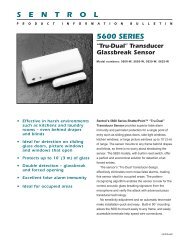
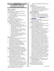
.$ $ "+ ,!$$(,$# $"# $ !%' $ (&) #*1 / 2Doors &WindowsChimeDoors MotionBypassFIREArmMotionSensorsDisarm3 / 4 5 / 6 7 / 8TimePOLICESensorTest WeeklyLights<strong>System</strong>StatusOnAUX9 / 0OffH O M E S E C U R I T YC O D EH O M E C O N T R O LE M E R G E N C YIntroduction toYour <strong>Security</strong><strong>System</strong>Your security system uses wireless technology to warn your family about intrusion,carbon monoxide and fire. It may also be used to control lights and appliances withinyour home. The system has the capabilities of communicating with a central monitoringstation and sending messages to a numeric pager or remote phone (voice eventnotification).This manual describes how to operate your system. It will guide you through programminginstructions for system features as well as basic arming and disarming commandsfor the system.* KeychainTouchpadDoor/WindowSensorMotionSensorSmokeSensorRemote HandheldTouchpad* Dialog QS 1500Touchtalk Interactive Keypad*RF ElectronicThermostatLamp* Universal * *Module ModuleApplianceModule<strong>Security</strong> <strong>System</strong> ComponentsThe security system uses devices called sensors that use radio waves to communicatealarms to the Control Panel (panel).The system is supervised, meaning that the panel checks the status of each sensor todetect problems. If the panel detects trouble it will notify you with beeps and indicatorlights on the panel itself.Your security system installation may include any of the following devices:Control PanelThe Control Panel is used to operate and program your security system. It communicatesto you through voice messages, beeps, and by lighting or flashing buttons. Thepanel can communicate to a central monitoring station, numeric pager, remote phone,or all three.TouchpadsRemote Handheld Touchpads are used to control the security system primarily fromwithin the home.* Dialog QS 1500 Touchtalk Interactive Keypads are used to control the securitysystem primarily from within the home. It’s used to hear commands from the controlpanel when it’s active.Keychain Touchpads are used to control the security system from within or near theoutside of your home. These touchpads can either be 2 or 4-button.SensorsIndoor Motion Sensors detect motion in a protected indoor area. When motion isdetected the panel may respond by sounding chimes or an alarm.<strong>Simon</strong> <strong>Security</strong> <strong>System</strong> 1
Outdoor Motion Sensors detect motion in a protected outdoor area. When motion isdetected, the system may respond by sounding chimes or turning on outside lights.These sensors are not used for intrusion detection.Door/Window Sensors detect the opening of a door or window.Smoke Sensors detect smoke and a significant rise in temperature. They have a built insiren that sounds when smoke or a significant rise in temperature is detected.Freeze Sensors detect furnace failure. If the inside temperature drops below 41°F, thesensor will notify the panel. The sensor will send a restore signal to the panel when thetemperature rises to 50°F.Carbon Monoxide Sensors detect carbon monoxide. They have a built in siren thatsounds when carbon monoxide is detected.Modules* Appliance Modules can be programmed to turn appliances or fluorescent lights onand off.* Lamp Modules can be programmed to turn non-fluorescent lights on and off.* Universal Modules are primarily used for controlling devices other than appliancesand lamps. Check with your installer for other applications.Audio Verification Module (AVM) is primarily used by the central monitoring stationto monitor sounds and verbally communicate with a person inside the home. This featureis similar to a speaker phone feature on a phone.* Dialog RF Electronic Thermostat is primarily used to monitor and control HVACsystems from the security system.* Water Resistant Personal Help Button is a wireless device used for activatingpolice, medical or auxiliary alarms through your security system.* Dialog Telephone Interface Module is a battery operated communication linkbetween the security system control panel and the central monitoring station.* Ethernet Interface Module is designed to provide access to the panel via a computerand the premisesconnect.com website.• Installers - to aid in installation and maintenance of security systems.• Dealers - to simplify customer and account management.• First Responders - to identify where and how to respond.• Customers - to control their security system.* Not investigated for use by ULHow YouCommunicateto Your <strong>System</strong>NoteThe Master Access Codedefault is 1-2-3-4 when thesecurity system is shippedfrom the factory. You shouldchange your code after yoursystem is installed (see“Programming Your <strong>System</strong>”).Sending commands or instructing your security system can be done through the panel,touchpads, a remote telephone or a computer.Control PanelYou can enter commands for your security system through simple key presses on thepanel. Depending on how your system is programmed, you may need to enter an accesscode for certain commands. An access code is a numeric code that allows authorizationto operate your security system.Remote Handheld TouchpadThis touchpad gives you the option to enter commands from any room in your house.You can enter commands through simple key presses on the touchpad.Dialog QS 1500 Touchtalk Interactive KeypadThis keypad gives you the option to enter commands from a remote location (awayfrom the control panel) in your house. It also allows you to hear panel messages whenthe <strong>System</strong> Status button is pressed.2<strong>Simon</strong> <strong>Security</strong> <strong>System</strong>
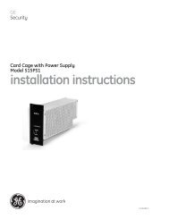
Keychain TouchpadKeychain Touchpads are handy for simple arming, disarming and light control functions.They are portable and can be carried off-site in a purse or pocket.TelephoneTouchtone telephones can be used to communicate with your system while you areoff-site. Ask your installer if you have this feature.ComputerWith the addition of the Ethernet Interface module a computer can be used to controlyour system.How to UseYour ControlPanelNoteIt may be necessary to enteran access code to arm yoursystem. Check with yourinstaller to see if this featureis enabled.The panel interface consists of four rows of buttons.• HOME SECURITY• CODE• HOME CONTROL• EMERGENCYHOME SECURITY, HI 9 E @ M I JE 5 A I HI5 O I JA 5 J= JK I0 - 5 - + 7 4 16 ;) H, EI = HThe Home <strong>Security</strong> buttons are used to arm and disarm doors, windows and motionsensors in your system. The <strong>System</strong> Status button is used to give information on systemactivity.ArmTurn on intrusion/burglary protection for your system. You can arm door/window sensors,motion sensors or both depending on the buttons you press.DisarmTurn off intrusion/burglary protection for your system. Only intrusion/burglary sensorssuch as doors/windows and motion are disarmed. Environmental sensors, such assmoke and carbon monoxide stay active at all times.<strong>System</strong> StatusPress to hear information about your system. If the button is lit, there is a problem withthe system. If the button is blinking, an alarm has occurred. Press the button to hearwhat is wrong with the system. (See “Status Beeps”.)Exit DelayExit Delay is the amount of time the system gives you to exit the home before the systemis armed (between 5 and 254 seconds). This is programmed by the installer. Whenyou arm you will hear beeps during the exit delay (see the table “Status Beeps” of thismanual to determine the meaning of panel/system beeps).Your Exit Delay is set for ___ seconds.<strong>Simon</strong> <strong>Security</strong> <strong>System</strong> 3
Entry DelayEntry Delay is the amount of time the system gives you to disarm the system after enteringthe home (between 5 and 254 seconds). This is programmed by the installer. Whenyou enter your home you will hear beeps during the entry delay (see the table “StatusBeeps” of this manual to determine the meaning of panel/system beeps).Your Entry Delay is set for ___ seconds.NoteThe designated door may beopened and closed once. Ifyou close the designateddoor behind you when youexit, you will have to disarmthe system upon reentering.Leave the designated dooropen while using the QuickExit feature.Quick ExitThe Quick Exit feature is used when someone wants to briefly leave while the home isstill armed (i.e. get the newspaper). This feature needs to be enabled by your installer.When you press the Disarm button the panel will announce exit time on. This will allowa designated exit door to be open for up to 2 minutes without triggering an alarm.LatchkeyLatchkey is used to notify parents, via a numeric pager or remote phone, if children donot arrive home at a predetermined time and disarm the system. For example, you setthe Latchkey time for 3:00 pm. If the system isn’t disarmed by that time a message issent to your numeric pager (see “Numeric Pager”) or remote phone.SubdisarmIf your system includes 24-hour protection sensors on items such as gun or jewelrycases, you must subdisarm the panel before accessing these areas to avoid causing analarm. Environmental sensors, such as smoke and carbon monoxide stay active at alltimes.¾Arming Your <strong>System</strong> with Doors & Windows Closed1. Close all doors and windows.2. Press Arm Doors & Windows button.3. Enter Access Code (if needed).Panel announces, Doors and windows on, Arm Doors & Windows light will be lit andthe exit delay will begin.NoteAny sensors that arebypassed by the system willNOT be protecting yourhome.NoteNo Entry Delay can be usedin two ways. First, you canuse this feature when you’restaying at home, after you’vearmed the system (i.e. whenyou’re asleep). Second, youcan use this when you’reaway from your home. Toavoid causing an alarm, youmust disarm the system witha remote handheld touchpador keychain before enteringyour home. Check with yourinstaller to find out how thisoption is programmed.¾Arming Your <strong>System</strong> with Doors or Windows Open (Indirect Bypassing)1. Close all doors and windows except the ones you wish to remain open.2. Press Arm Doors & Windows button.3. Enter Access Code (if needed).Panel announces any protected doors or windows that are open. Any sensors that areopen when the system is armed will be bypassed automatically after exit. Arm Doors &Windows light will be lit and the exit delay will begin.¾Arming Your <strong>System</strong> with No Entry Delay1. Close all doors and windows.2. Press Arm Doors & Windows button twice.3. Enter Access Code (if needed).Panel announces, Doors and windows on, no entry delay. Arm Doors & Windows lightwill blink and the exit delay will begin.¾Arm Motion Sensors1. Press Arm Motion Sensors button once.2. Enter access code (if needed).4<strong>Simon</strong> <strong>Security</strong> <strong>System</strong>
NoteThis feature is most likelyused when there is no oneon the premises.Panel announces, Motions on. Arm Motion Sensors light will be lit and the exit delaywill begin.¾Activate Latchkey Feature1. Press the Arm Motion Sensors button twice.2. Enter Access Code (if needed).Panel announces, Motions on, Latchkey on. Arm Motion Sensors light will blink andthe exit delay will begin.¾Disarming Your <strong>System</strong>1. Upon reentering your home the entry delay will begin.2. Status beeps will sound.3. Enter your access code using the Code buttons.Panel announces, <strong>System</strong> disarmed and the Disarm light will be lit.!WarningIf you enter you home and you hear alarm sirens, or if controlled lights thatshould be off are on, an intruder may be inside or another emergency mayhave occurred. Leave immediately and call for help.!¾Subdisarm Your <strong>System</strong>1. Enter your Master Access Code while the system is disarmed.Panel announces, <strong>System</strong> disarmed. Disarm button light blinks and the system is subdisarmed.When you’ve finished accessing the protected areas, press the Disarm buttonagain. Panel announces, <strong>System</strong> disarmed. Disarm button light stops blinking.<strong>System</strong> is in Disarm mode.If You Never Leave After ArmingYour panel can be programmed to recognize that you never left the premises. If youpress the Arm Doors & Windows button and the Arm Motion Sensors button butdon’t exit before the exit delay expires, the panel will not arm the motion sensors.Check with your installer to find out if this feature is enabled for your panel.If You Forgot Something After ArmingYour panel can be programmed to recognize when you leave the premises then quicklyreenter. The panel will restart the exit delay to give you time to collect your things andleave again. You must leave before the exit delay expires or disarm the system. Askyour installer if this feature is enabled for your system.Arming When the Panel Battery is LowYour panel may be programmed so that you cannot arm the system if the panel batteryis low. Ask your installer if this feature is enabled for your system.Note40 keypresses for invalidcodes (i.e. 10 invalid 4-digitcodes) will cause a systemaccess alarm. The alarmlocks all touchpads, exceptkeychains, for 90 seconds.CODE ! "# $ % &' + , -There are 5 CODE buttons located in the second row of the panel. Each button represents2 numbers. The left CODE button is 1/2, which means that this button is pressedwhen entering either 1 or 2. For example, if your access code is 1-2-3-4 you must pressthe 1/2 button twice and the 3/4 button twice to enter that access code. Access codelengths need to be between 3 and 6 digits and are set by the installer.<strong>Simon</strong> <strong>Security</strong> <strong>System</strong> 5
HOME CONTROL+ D E A, HI JE 6 E A5 A I H BB0 - + 6 4 * O F = I I EC D JIThe Home Control buttons are used to monitor activity within and around the home.They are not used for intrusion protection. If any of the Home Control buttons arepressed and a sensor or module is not associated (programmed) with this feature thepanel will announce, Function not available.Chime DoorsChime Doors is used to signal (chime) when a protected door is opened while the systemis disarmed. The panel will announce the door that has been tripped and chimetwice (ask your installer how this feature is programmed). This is a nice feature to use ifyou’re busy in one part of your home and you want to know when family members aregoing in and out of your home.¾Turn Chime Doors on:1. <strong>System</strong> must be disarmed. Press Chime Doors button.Panel will announce, Chime on. Chime Doors button will be lit.¾Turn Chime Doors off:1. Press Chime Doors buttonPanel will announce, Chime off. Chime Doors button no longer litNoteIf there are no SpecialMotion Chime sensors inyour system, the ChimeSpecial Motion button canbe used for Direct Bypassingand Unbypassing. See theArming Your <strong>System</strong> withDirect Bypassing and ArmingYour <strong>System</strong> withDirect Unbypassing sectionsfor more information.NoteYou can only use this featureif there are no SpecialMotion Chime sensors inyour system.NoteYou can only use this featureif there are no SpecialMotion Chime sensors inyour system.Chime Special MotionThis is used to detect movement within a specific area. These Motion Sensors are notused for intrusion protection. The panel will chime three times and announce (seeOption 41) the sensor that has been tripped. Use the same panel procedures as ChimeDoors, except, with the Chime Special Motion button.If you have Motion Sensors located in areas such as in a patio area or at the front doorand you want to know when someone is approaching these areas, you would use thisfeature.Direct BypassingDirect Bypassing refers to turning off (bypassing) certain sensors while the system isarmed.1. Press the Bypass button until you reach the sensor to be bypassed (sensor must currentlybe unbypassed).2. Enter Master CodeDirect UnbypassingDirect Unbypassing refers to turning on (reactivating) bypassed sensors while the systemis armed.1. Press the Bypass button until you reach the sensor to be unbypassed (sensor mustcurrently be bypassed).2. Enter Master Code. OR Change arming level.Time Activated LightsTurn on designated lights (with Lamp Modules) at a specific time. You can programwhat time the lights go on and off (see Programming - Light Control).¾Turn Time Activated Lights on:1. Press Time Lights button.6<strong>Simon</strong> <strong>Security</strong> <strong>System</strong>
Panel will announce, time activated light on. Time Lights button will be lit.¾Turn Time Activated Lights off:1. Press Time Lights button.Panel will announce, time activated light off. Time Lights button no longer lit.Sensor Activated LightsTurn on designated lights (with Lamp Modules) when a sensor is tripped. You can programlockout times when Sensor Activated Lights won’t be active (see ProgrammingOptions 36 and 37).¾Turn Sensor Activated Lights On:1. <strong>System</strong> must be disarmed. Press Sensor Lights button.Panel will announce, sensor activated lights on. Sensor Lights button will be lit.¾Turn Sensor Activated Lights Off:1. Press Sensor Lights button.Panel will announce, sensor activated lights off. Sensor Lights button no longer lit.Controlling Individual LightsLights with even unit numbers (2, 4, 6, 8) can be controlled from either the panel or aRemote Handheld Touchpad. Lights with odd unit numbers (1, 3, 5, 7) can only becontrolled from a Remote Handheld Touchpad. Lights with unit numbers 9-16 cannotbe individually controlled.¾Turn on individual lights that are controlled by Lamp Modules:1. Press Lights On button once.2. Press the number (2, 4, 6, 8) of the lamp module you want to turn on.Panel will announce, light on.¾Turn off individual lights that are controlled by Lamp Modules:1. Press Lights Off button once.2. Press the number (2, 4, 6, 8) of the lamp module you want to turn off.Panel will announce, light off.All Lights On¾Turns on lights that are controlled by Lamp Modules:1. Press Lights On button twice.Panel announce, Lights on.All Lights OffTurns off lights that are controlled by Lamp Modules.1. Press Lights Off button twice.Panel announces, Lights off.NoteEnabling Silent Exit doublesthe Exit Delay Time.Silent ExitThis feature silences the status beeps that accompany the exit delay (see Status Beeps).Press Chime Doors after you arm the system to silence status beeps. The panel willstill beep at the beginning and end of the exit delay.<strong>Simon</strong> <strong>Security</strong> <strong>System</strong> 7
EMERGENCY- - 4 / - + ;. 14 -2 1+ -) 7 :Press FIRE, POLICE, or AUX for 2 seconds (or press twice quickly) to call the centralmonitoring station and notify them of a non-medical call for help.How Your<strong>System</strong>Communicatesto YouNoteThe panel will not give voicemessages during an AVMsession. Talk to your securitysystem dealer to see if yourpanel has the AVM option.NoteYou may receive a differentnumber of status beeps ifbuttons are pressed quicklyYour system responds to you through the use of panel voice messages, status beeps,alarms, panel indicator lights, and to a numeric pager or remote phone if programmed.Panel Voice MessagesWhen you press the buttons on the panel or the touchpads, the panel responds withvoice messages. Panel voice can be enabled or disabled (see “Options”).These messages may respond with system information or prompt you to take furtheraction. For example, if you want to disarm the system and you press the DISARM button,the panel responds by announcing, “Please enter your access code.”If you press a button and the feature has not been programmed, the panel voice willrespond with “Function not available.” An example of this would be pressing LightsSensor (activated) button when you have no sensor activated lights in your system.Status BeepsStatus beeps are used to indicate key presses, status, and problems with the system.They can be enabled or disabled (see “Options”). The following table describes statusbeep activity..Status BeepsActivityARM Doors & WindowsARM Motion SensorsARM Doors/Windows &Motion SensorsDISARMCHIME DOORSCHIME SPECIAL MOTIONTrouble BeepsNo Activity BeepsBeep ResponseExit delay and Entry delay beeps sound 2 timesevery 5 seconds and 2 times per second duringthe last 10 seconds (if Silent Exit is used, the Exitdelay beeps will only sound twice when you armand twice when the Exit delay expires)Exit delay and Entry delay beeps sound 3 timesevery 5 seconds and 3 times per second duringthe last 10 seconds (if Silent Exit is used, the Exitdelay beeps will only sound 3 times when you armand 3 times when the Exit delay expires)Exit delay and Entry delay beeps sound 4 timesevery 5 seconds and 4 times per second duringthe last 10 seconds (if Silent Exit is used, the Exitdelay beeps will only sound 4 times when you armand 4 times when the Exit delay expires)1 beep2 beeps (feature must be programmed by installer)3 beeps (feature must be programmed by installer)6 beeps every minute. Press the SYSTEM STA-TUS button to stop beeps for 4 hours20 beeps every minute for 5 minutes (feature mustbe programmed by the installer)8<strong>Simon</strong> <strong>Security</strong> <strong>System</strong>
Alarm Sirens and Lamp ModulesExterior and interior sirens make 3 different alarm sounds on the premises, each indicatinga different type of alarm. Sirens are programmed by the installer to time-out andstop sounding after a specified time.Use the following table to understand the siren sounds used by the security system.Temporal 3 refers to a continuous pattern of 3 siren pulses then off for 1.5 seconds, 3siren pulses then off for 1.5 seconds.Alarm Siren and X10 Light InformationFire Intrusion EmergencyX10 Lights Steady Flashing SteadyX10 Siren Steady Steady Alarm beepsInterior & Panel Siren Temporal 3 Steady Fast on/offExterior Siren Temporal 3 SteadyPanel Indicator LightsUse the following table to understand the panel indicator lights.Panel Indicator LightsButtonWhen the Button Light isOnWhen the ButtonFlashesArm Doors & Windows Doors/Windows armed Doors/Windows armed& No Entry Delay onArm Motion Sensors Motion Sensors armed Motion Sensors armed& Latchkey onDisarm <strong>System</strong> disarmed <strong>System</strong> subdisarmed<strong>System</strong> Status<strong>System</strong> trouble or Open Sensor<strong>System</strong> in alarmChime Doors Door will cause chime _________________Chime Special Motion Motion will cause chime _________________Time Lights Time activated lights on _________________Sensor Lights Sensor activated lights on _________________Numeric PagerYou may program your security system to send a numeric message indicating systemactivities to your pager. The system will send the message twice. See “ProgrammingInstructions”.Use the following table to determine what the numeric message is reporting.Numeric Pager ReportingReportsNumericMessageReportsNumericMessagePhone Test -101 -101 Fail to Open -112 -112<strong>Simon</strong> <strong>Security</strong> <strong>System</strong> 9
Numeric Pager ReportingAC Power Restore -102 -102 Fail to Close -113 -113AC Power Failure -103 -103 Bypass -114 -114Latchkey -104 -104 Restoral -115 -115No Activity -105 -105 Supervisory -116 -116Panic -106 -106 Trouble -117 -117Emergency -107 -107 Tamper -118 -118Intrusion -108 -108 Gas -119 -119Fire -109 -109 Freeze -120 -120Disarming -110 -110 Environmental -121 -121Arming -111 -111 Programming/Sensor Test -122 -122Dialog QS 1500 Touchtalk Interactive KeypadWith the addition of the QS 1500 Keypad, the user is able to hear the voice feedbackthat is heard at the control panel. This enables the user to hear voice feedback fromremote locations (where the keypad is mounted).Canceling andPreventingAccidentalAlarmsOne of the biggest concerns you might have regarding your security system, is causingan accidental alarm. Most accidental alarms occur when leaving the residence afterarming the system, or, before disarming the system upon your return.Canceling Accidental AlarmsThere is a communicator delay (Dialer Delay) of 30 seconds programmed into thispanel. The panel will delay 30 seconds before dialing the central monitoring station,numeric pager or remote phone to send reports. You can have your installer programthis delay time between 0 - 254 seconds.You have ___ seconds to cancel an accidental alarm.To cancel an accidental alarm before the programmed dialer delay time expires, enteryour access code.Guidelines for Preventing Accidental AlarmsThe following guidelines will go a long way toward preventing accidental alarms.• Close doors and windows before you leave your house.• Gather your belongings, so you can exit immediately after arming the system.• Always enter and exit within the programmed delay times.• Make sure you leave through a door that has a delay time set for it.• Disarm your system immediately upon returning home.• Be aware of the devices in your security system and learn how each one operates.• If you have pets, ask your installer if you need pet lenses in your motion detectors.• Check the location of your smoke detectors. Smoke detectors near bathrooms andkitchens can be tripped by steam and smoke from cooking.• Take note of system beeps, voice announcements and indicator lights which indicatethe current system status.10<strong>Simon</strong> <strong>Security</strong> <strong>System</strong>
How to Use anOff-Site PhoneNoteYou may have to performsteps 1 & 2 more than once.Ask your installer how yoursystem is programmed.You may use an off-site phone to arm/disarm your panel, turn lights on and off, checksystem status, or conduct an audio session (ask your installer if you have this feature).¾How to gain access to the Control Panel:1. Call the panel phone number and let the phone ring once then hang up.2. Wait 10 - 40 seconds and call the panel again.3. The panel should answer on the first ring. The panel will announce “<strong>System</strong> On”.4. Press the * button on your telephone and you will hear “<strong>System</strong> Activated”.At this point you may perform the actions listed in the following table of phone commands.CODE refers to the master and access codes programmed into your system.Phone CommandsPanel FunctionPhone CommandDISARM ‚ + CODE + 1ARM Doors/Windows ‚ + CODE + 2ARM Doors/Windows with No Entry Delay ‚ + CODE + 2 + 2ARM Motions ‚ + CODE + 3ARM Motions with Latchkey ‚ + CODE + 3 + 3ARM Doors/Windows and Motions ‚ + CODE + 2 + 3ARM Doors/Windows with No Entry Delayand Motions with Latchkey‚ + CODE + 2 + 2 + 3 + 3Lights On/Off ‚ + CODE + 0<strong>System</strong> Status ‚ + CODE + # + 1AVMNotePhone commands cannot be used when thepanel is in AVM mode.‚ + CODE + 5 + X (X = a commandfrom the Audio Verification Set, 1=Talk,2=VOX, 3=Listen)Hang Up‚ + CODE + 9 (Phone Command Mode)‚ + 99 (AVM Mode)If you are interactive with your panel and the panel hangs up on you, the system iscalling in a report to the central monitoring station, pager or remote phone due to anaction made by you or someone at the security system site.UsingTouchpads andKeypadsTouchpads and keypads are used to control the security system from any locationwithin or near your home.Touchpads and KeypadsInterfacing with the system using a Remote Handheld Touchpad and Dialog QS1500Touchtalk Interactive Keypad is similar to using the panel.<strong>System</strong> StatusPress <strong>System</strong> Status once to hear information about your system from the panel. See“Status Beeps”.ARM Doors & WindowsPress Arm Doors & Windows button once to turn the security system protection onfor all protected doors and windows.<strong>Simon</strong> <strong>Security</strong> <strong>System</strong> 11
Press twice to eliminate the pre-programmed entry delay.NoteDepending upon how yourdealer programmed yourpanel, you may be requiredto enter your access code toarm the system.ARM Motion SensorsPress Arm Motion Sensors button once to turn protection on for all Motion Sensors.Use when no one is home. This is usually used in combination with ARM Doors &Windows. Press twice to activate the Latchkey feature.DisarmPress Disarm button once and enter your access code using the NUMERIC buttons toturn security protection off. To subdisarm the system, enter the master access code.SubdisarmEnter your master access code using the NUMERIC buttons while the system is disarmed.Panel will announce, system disarmed. The Disarm button on the panel willbegin to blink.Lights¾Turn on individual lights that are controlled by Lamp Modules:1. Press Lights On button once.2. Press the number of the lamp module you want to turn on.Panel will announce, light on.¾Turn off individual lights that are controlled by Lamp Modules:1. Press Lights Off button once.2. Press the number of the lamp module you want to turn off.Panel will announce, light off.¾Turn on all lights that are controlled by Lamp Modules:1. Press Lights On button twice.Panel will announce, lights on.¾Turn off all lights that are controlled by Lamp Modules:1. Press Lights Off button twice.Panel will announce, lights off.EmergencyPress both EMERGENCY buttons for 3 seconds to cause the system to call a centralmonitoring station to report a non-medical emergency.Keychain TouchpadFor any keypress on the Keychain Touchpad, hold the button until the indicator lightblinks.If your installer programmed the Keychain Touchpad with no entry delay, and youarmed the system with the Keychain Touchpad, you must disarm your system beforeentering the home to avoid causing an alarm.If your installer programmed your system for Remote Touchpad Arming, you mustenter your home to start the entry delay before you can use your Keychain Touchpad todisarm the system.12!WarningTo avoid causing false alarms, check with your installer on how your touchpadoptions are programmed!<strong>Security</strong> system devices cannot compensate you for the loss of life<strong>Simon</strong> <strong>Security</strong> <strong>System</strong>
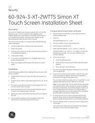
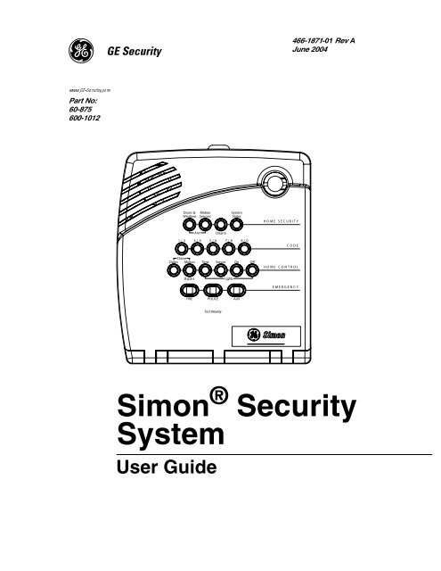
NoteFor any keypress on theKeychain Touchpad, holdthe button until the indicatorlight blinks.NotePanic alarms need to besilenced from the panel, aremote handheld touchpador another keychain touchpad.They cannot besilenced from the same keychainthat activated thealarm.Using aComputerRF ThermostatOperationProgrammingYour <strong>System</strong>LOCK Press once to arm doors and windows.LOCK Press twice to arm doors, windows, and Motion Sensors.LOCK Press 3 times to arm doors, windows, Motion Sensors, and to activatethe Latchkey option.LOCK and UNLOCKPress both buttons simultaneously for 3 seconds to send a panic (intrusion,silent, or non-medical emergency) alarm to the central monitoringstation. Check with the installer to find out how the keychain touchpadpanic buttons will operateUNLOCK Press to disarm your security system.STAR Can be programmed to control a device connected to a UniversalModule.LIGHT Can be programmed to control a device connected to a Lamp Module.One press all lights on Lamp Modules turn on. Press again all lights turnoff.With a Ethernet Interface module installed in your panel, you can control your systemvia the premisesconnect.com website.Premisesconnect.com can be used by:• Installers - to aid in installation and maintenance of security systems.• Dealers - to simplify customer and account management.• First Responders - to identify where and how to respond.• Customers - to control their security system.For more information on controlling your system via a computer, visit premisesconnect.com.These guidelines must be followed for RF Thermostat operation:• The panel needs to be armed to Doors & Windows and Motion Sensors to enterEnergy Saving Mode.• If there are no Motion Sensors in the system, the Motion Sensors button must stillbe pressed.• Both Option 81 and 82 can be turned on at the same time.• Thermostat has to be in Auto Mode for Options 81 and 82 to work correctly.• When the panel is disarmed the thermostat returns to normal operating mode.The programming decals are visible when you open the panel cover (see below).These decals are designed to make system programming easier for you. Always beginby entering your master access code. Then, choose an operation from the STARTMENU. Follow the prompts and flow arrows to complete the desired task. Notice thebutton flow diagrams following the Instruction Summary.<strong>Simon</strong> <strong>Security</strong> <strong>System</strong> 13
1 / 2SpecialDoors MotionChimeDoors & MotionWindows SensorsFIREPOLICETest WeeklyStatusArm Disarm <strong>System</strong>3 / 4 5 / 6 7 / 8 9 / 0Time SensorLightsOnAUXOffH O M E S E C U R I T YC O D EH O M E C O N T R O LE M E R G E N C YSTART MENUVersion 3Add Delete Cancel Test<strong>System</strong> should be checkedby a qualified technicianat least every three years.MAIN MENUAccess ClockOption #Code Set01 2 3Note:Entry/Exit CONTROL MENUUnit # DelayTime - Hours + Hold key or pressrepeatedly until youhear the desired item.4 5 6 7 8 9DeleteMinutes +To delete an option or access codeDeleteAdd Optionpress and follow the voiceOption #1: Panel Beepsprompting.Option #2: Panel VoiceDONEOption #3: Latchkey TimeAdd Access CodeDONE CancelOption #36: Sensor Activated Light Lockout Start TimeAdd Access CodeOption #37: Sensor Activated Light Lockout Stop Time Press, thenIf you make a mistake or want toCancelOption #41: Chime VoiceSee NoteOption #42: Speaker Volumeuse red numbers to enter 4-digit code.start over pressOption #43: Pager Phone NumberOption #55: Status Beep VolumeSet ClockSensor or Phone TestTestAdd Option #Clock Set Hours Minutes DONEPressand follow voice prompts. PressTo select a test, press andSee NoteSee Notefollow the voice prompting.1.Press Down* Press for programinformation.* ControlLight**Sensor/* Remote* Sensors -*422-2806 Rev A2.OpenCoverInstructionSummaryFigure 1. Opening the panel coverNoteIf Trouble Beeps are turnedon, the panel will sound sixtrouble beeps every minutethe panel cover is open. Askyour installer if TroubleBeeps are turned on for yoursystem.Programming InstructionsUse the following instructions to access the programming buttons and programmingdecals.1. <strong>System</strong> must be disarmed. Open the Panel Cover by pressing the plastic latch onthe top of the panel. When you open the cover you will immediately be promptedby the panel voice to use the numbered keys to enter your ID.Version 3* Press for programinformation.AddSTART MENUDelete CancelTest<strong>System</strong> should be checkedby a qualified technicianat least every three years.Unit #* ControlLight0Entry/ExitDelay*MAIN MENUSensor/ AccessOption #Code* * Remote1CONTROL MENUTime* Sensors -*2-ClockSet3Hours +Note:Hold key or pressrepeatedly until youhear the desired item.422-2806 Rev AInstructionSummaryAdd Option4 5Option #1: Panel BeepsOption #2: Panel VoiceDONEOption #3: Latchkey TimeOption #36: Sensor Activated Light Lockout Start TimeOption #37: Sensor Activated Light Lockout Stop TimeOption #41: Chime VoiceOption #42: Speaker VolumeOption #43: Pager Phone NumberOption #55: Status Beep VolumePressAdd Option #and follow voice prompts.See Note6 7 8Minutes +Add Access CodeAdd Access Code DONEPress, thenSet ClockSee Noteuse red numbers to enter 4-digit code.Clock Set Hours Minutes DONEPressSee Note9DeleteTo delete an option or access codeDeletepress and follow the voiceprompting.CancelIf you make a mistake or want toCancelstart over pressSensor or Phone TestTestTo select a test, press andfollow the voice prompting.NoteThe Master access code is1-2-3-4 when the panel isshipped. You should changeyour Master Access Codeafter your system is installed(see “Access Code”).2. Enter the Master Access Code.3. The system voice will prompt you to begin with the START MENU.The START MENU includes the following buttons:• Add• Delete• Cancel14<strong>Simon</strong> <strong>Security</strong> <strong>System</strong>
• Test• Clock SetPress the appropriate button.4. After pressing the appropriate button on the START MENU, the system voicewill prompt you to use the MAIN MENU.The MAIN MENU includes the following buttons:• Light Control• Option #• Sensor/Remote• Access CodePress the appropriate button. Depending on the button you pressed, the system willprompt you to continue by pressing other buttons on the panel.NoteCodes are always needed todisarm the system. Dependingon the panel configuration,codes may be neededto arm the system. Checkwith the installer for yoursystem configuration.Access CodesYour security system has a master access code and access codes 1-5 used for armingand disarming the panel. The master code is used for disarming and programming yoursystem. Access codes 1-5 are generally used for children or as temporary codes for ababy-sitter or service personnel.Your system may be set up so that the master code or an access code is required whenarming. If so, the panel will prompt you to enter a code when you attempt to arm thesystem.NoteBecause different codes can be entered using the same button presses, you have to usecaution when programming different codes. You need to ensure that one access code doesnot use the same button presses as other access codes. For example, if the master code is1234, do not program another code to be 2244. The panel would interpret these codes to bethe same code.¾How to change an Access Code:1. Open the cover of the panel.2. The panel voice prompts you to Use numbered keys to enter ID. Enter your masteraccess code using the numbered keys.3. The panel voice prompts you to Please select from START MENU. Press the Addbutton on the START MENU.4. The panel voice prompts you to Select from MAIN MENU. Press the AccessCode button on the MAIN MENU.5. The panel voice responds with Master Code, press again for next access code,DONE to select or press CANCEL to quit. Press the access code button again tohear the next access code. When you hear the access code you wish to changepress the DONE Button.6. Enter 3-6 new numbers using the numbered keys. (Access Code length is programmedby the installer.)7. Close the panel cover.¾How to Delete an Access Code:Delete Access CodeDelete<strong>Simon</strong> <strong>Security</strong> <strong>System</strong> 15
1. Open the cover of the panel.2. The panel voice prompts you to Use numbered keys to enter ID. Enter your masteraccess code using the numbered keys.3. The panel voice prompts you to Please select from START MENU. Press theDelete button on the START MENU.4. The panel voice prompts you to Select from MAIN MENU. Press the Access Codebutton on the MAIN MENU.5. The panel voice responds with Access Code 1, press again for next access code,DONE to select or press CANCEL to quit. Press the access code button again tohear the next access code. When you hear the access code you wish to delete, pressthe DONE Button. The panel voice responds with Access Code X deleted.6. Close the panel cover.Light ControlYou system has the ability to control lights from the panel. A specific light or group oflights can be programmed to turn on and off at designated times.House CodeRefers to a group of lights that can be controlled from the panel.NoteThe panel lists house codes A - O. Ask your installer what house code your lights are set upon. Your house code for lights is ___.Unit NumberRefers to a specific light within a house code.ProgrammingOptions¾How to set time for light control:1. Open the cover of the panel.2. The panel voice prompts you to Use numbered keys to enter ID. Enter your masteraccess code using the numbered keys.3. The panel voice prompts you to Please select from START MENU. Press the Addbutton on the START MENU.4. The panel voice prompts you to Select from MAIN MENU. Press the Light Controlbutton on the MAIN MENU.5. The panel voice responds with House Code is *, press again to change or press unitnumber. This is the House Code that was set by your installer. Don’t change it.Press the Unit # button.6. The panel responds with Unit #1 press again to change or select from controlmenu. Keep pressing the Unit # button until the correct unit is selected.7. Press the Time button on the control menu. The panel voice prompts you, On timeis **** to change press hours and minutes then press done.8. Press the Hours and Minutes buttons to set the correct on time.9. Press Done. Panel will announce, Off time is **** to change press hours and minutesthen press done.10. Press the Hours and Minutes buttons to set the correct off time.11. Press Done. Panel will announce the unit number with the on and off times you justprogrammed.The following table is a list of options you can change.Programming OptionsOption # Add Delete01 - Panel Beeps On Off02 - Panel Voice On Off* See “Option 43 - Pager/Voice Event Notification Phone Number”16<strong>Simon</strong> <strong>Security</strong> <strong>System</strong>
Programming OptionsOption # Add Delete03 - Latchkey Time 12:00 am (midnight) to 11:59 pm Off36 - Sensor Activated LightLockout Start Time37 - Sensor Activated LightLockout Stop Time12:00 am (midnight) to 11:59 pm Off12:00 am (midnight) to 11:59 pm Off41 - Chime Voice On Off42 - Speaker Volume 1 - 8 8 (highest)43 - Pager/Voice Event NotificationPhone NumberUp to 26 digits*Off55 - Status Beep Volume 1 - 10 781 - Heating Set Point 51°F - 91°F Off82 - Cooling Set Point 51°F - 91°F Off* See “Option 43 - Pager/Voice Event Notification Phone Number”Press Add in the START MENU and follow the voice prompts to turn an option on.Press Delete in the START MENU to turn an option off.When entering a single digit option number (1-9), you must type a zero before thenumber (i.e. 01, 02,.....). All option numbers must be 2 digits.Option 01 - Status BeepsAdd this option to enable panel beeps. Status beeps are any beeps (including chimebeeps) that come from the panel. See “Status Beeps”.1. Open panel cover. Panel announces, Use numbered keys to enter ID.2. Enter Access Code using the numbered keys. Panel announces, Please select fromStart Menu.3. Press Add from the Start menu. Panel announces, Select from main menu.4. Press Option #. Panel announces, Option 1, press again for next option or done toselect5. Press DONE. Panel announces, Option 1 is on.Delete turns off panel piezo beeps.1. Open panel cover. Panel announces, Use numbered keys to enter ID.2. Enter Access Code using the numbered keys. Panel announces, Please select fromStart Menu.3. Press Delete from the Start menu. Panel announces, Select from main menu.4. Press Option #. Panel announces, Option 1, press again for next option or done toselect.5. Press DONE. Panel announces, Option 1 deleted.Option 02 - Panel VoicePanel Voice may be disabled, except for status messages, open sensor responses, andwhen in program mode.Add enables the panel voice.1. Open panel cover. Panel announces, Use numbered keys to enter ID.2. Enter Access Code using the numbered keys. Panel announces, Please select fromStart Menu.<strong>Simon</strong> <strong>Security</strong> <strong>System</strong> 17
NoteThe panel voice is always onfor status messages, opensensor responses and whenin program mode.3. Press Add from the Start menu. Panel announces, Select from main menu4. Press Option #. Panel announces, Option 1, press again for next option or done toselect.5. Press 02. Panel announces, Option 2, press again for next option or done to select6. Press DONE. Panel announces, Option 2 is on.Delete disables the panel voice.1. Open panel cover. Panel announces, Use numbered keys to enter ID.2. Enter Access Code using the numbered keys. Panel announces, Please select fromStart Menu.3. Press Delete from the Start menu. Panel announces, Select from main menu4. Press Option #. Panel announces, Option 1, press again for next option or done toselect.5. Press 02. Panel announces, Option 2 press again for next option or done to select.6. Press DONE. Panel announces, Option 2 deleted.Option 03 - Latchkey TimeNoteThe system clock must beset for Latchkey to function.Adding this option allows you to program Latchkey Time. Latchkey is used to notifyparents if children do not arrive home and disarm the system at a predetermined time.1. Open panel cover. Panel announces, Use numbered keys to enter ID.2. Enter Access Code using the numbered keys. Panel announces, Please select fromStart Menu.3. Press Add from the Start menu. Panel announces, Select from main menu4. Press Option #. Panel announces, Option 1, press again for next option or done toselect.5. Press 03. Panel announces, Option 3, press again for next option or set latchkeyhours and minutes, then press done.6. Press Hours and Minutes to set the time.7. Press DONE. Panel will announce Latchkey time that has been set.Delete turns off this option and Latchkey cannot be enabled when the panel is armed.1. Open panel cover. Panel announces, Use numbered keys to enter ID.2. Enter Access Code using the numbered keys. Panel announces, Please select fromStart Menu.3. Press Delete from the Start menu. Panel announces, Select from main menu4. Press Option #. Panel announces, Option 1, press again for next option or done toselect.5. Press 03. Panel announces, Option 3, press again for next option or done to delete.6. Press DONE. Panel announces, Option 3 deleted.Option 36 and 37- Sensor Activated Light Lockout Start andStop TimesAdding these options lets you control when sensor activated lights are active. The panelwill not turn on a light between the programmed start time (option 36) and the programmedstop time (option 37), even if sensor activated lights are on. Both optionsmust be programmed for this option to work correctly.For example, if you don’t want sensor activated lights to be active during daylighthours, set the lockout start time to begin at dawn and set the stop time (option 37) tocoincide with sunset.Option 36: Sensor Activated Light Lockout Start TimeAdd enables sensor activated light lockout start time (midnight to 11:59 P.M.).1. Open panel cover. Panel announces, Use numbered keys to enter ID.2. Enter Access Code using the numbered keys. Panel announces, Please select fromStart Menu.3. Press Add from the Start menu. Panel announces, Select from main menu18<strong>Simon</strong> <strong>Security</strong> <strong>System</strong>
4. Press Option #. Panel announces, Option 1, press again for next option or done toselect.5. Press 36. Panel announces, Option 36, press again for next option or set hoursand minutes, then press done.6. Press Hours and Minutes to set the time.7. Press DONE. Panel announces the time that has been set.Delete disables sensor activated light lockout start time. The panel will turn on a lightactivated by a sensor, if sensor activated lights are enabled.1. Open panel cover. Panel announces, Use numbered keys to enter ID.2. Enter Access Code using the numbered keys. Panel announces, Please select fromStart Menu.3. Press Delete from the Start menu. Panel announces, Select from main menu4. Press Option #. Panel announces, Option 1, press again for next option or done toselect.5. Press 36. Panel announces, Option 36, press again for next option or done todelete.6. Press DONE. Panel announces, Option 36 deleted.Option 37: Sensor Activated Light Lockout Stop TimeAdd enables sensor activated light lockout stop time (midnight to 11:59 P.M.).1. Open panel cover. Panel announces, Use numbered keys to enter ID.2. Enter Access Code using the numbered keys. Panel announces, Please select fromStart Menu.3. Press Add from the Start menu. Panel announces, Select from main menu4. Press Option #. Panel announces, Option 1, press again for next option or done toselect.5. Press 37. Panel announces, Option 37, press again for next option or set hoursand minutes, then press done.6. Press Hours and Minutes to set the time.7. Press DONE. Panel announces the time that has been set.Delete disables sensor activated light lockout stop time. The panel will turn on a lightactivated by a sensor at all times if sensor activated lights are enabled.1. Open panel cover. Panel announces, Use numbered keys to enter ID.2. Enter Access Code using the numbered keys. Panel announces, Please select fromStart Menu.3. Press Delete from the Start menu. Panel announces, Select from main menu4. Press Option #. Panel announces, Option 1, press again for next option or done toselect.5. Press 37. Option 37, press again for next option or done to delete.6. Press DONE. Panel announces, Option 37 deleted.Option 41 - Voice ChimeThe panel will verbally announce which chime sensor has been tripped if the chimefeature is on.Add enables chime voice.1. Open panel cover. Panel announces, Use numbered keys to enter ID.2. Enter Access Code using the numbered keys. Panel announces, Please select fromStart Menu.3. Press Add from the Start menu. Panel announces, Select from main menu4. Press Option #. Panel announces, Option 1, press again for next option or done toselect.5. Press 41. Panel announces, Option 41, press again for next option or done toselect6. Press DONE. Panel announces, Option 41 is on.<strong>Simon</strong> <strong>Security</strong> <strong>System</strong> 19
Delete disables chime voice. The panel will not announce which chime sensor has beentripped but will still chime 2 times for doors and 3 times for motion sensors when agiven sensor is tripped.1. Open panel cover. Panel announces, Use numbered keys to enter ID.2. Enter Access Code using the numbered keys. Panel announces, Please select fromStart Menu.3. Press Delete from the Start menu. Panel announces, Select from main menu4. Press Option #. Panel announces, Option 1, press again for next option or done toselect.5. Press 41. Panel announces, Option 41, press again for next option or done to delete6. Press DONE. Panel announces, Option 41 deleted.Option 42 - Speaker LevelWhen this option is turned on you can set the panel speaker level from 1 (the lowestvoice level) to 8 (the highest voice level). When you turn this option off, the speakerlevel is set to 8 (the highest voice level).Add allows you to set the speaker level from 1-8.1. Open panel cover. Panel announces, Use numbered keys to enter ID.2. Enter Access Code using the numbered keys. Panel announces, Please select fromStart Menu.3. Press Add from the Start menu. Panel announces, Select from main menu4. Press Option #. Panel announces, Option 1, press again for next option or done toselect.5. Press 42. Panel announces, Option 42, press again for next option or use numberedkeys to enter option.6. Enter the voice level (1 - 8) with the numbered keys.7. Panel announces the speaker level that has been selectedDelete sets the speaker level to 8 (the highest voice level).1. Open panel cover. Panel announces, Use numbered keys to enter ID.2. Enter Access Code using the numbered keys. Panel announces, Please select fromStart Menu.3. Press Delete from the Start menu. Panel announces, Select from main menu4. Press Option #. Panel announces, Option 1, press again for next option or done toselect.5. Press 42. Panel announces, Option 42, press again for next option or done to delete.6. Press DONE. Panel announces, Option 42 deleted.Option 43 - Pager/Voice Event Notification Phone NumberNoteMore than 3 or 4 pausesmay need to be added toensure a message isreceived.Add enables the pager/voice event notification (remote phone) phone number andallows you to program up to 26 digits, including pauses.Add 3 or 4 pauses to the end of the phone number to ensure the complete pager/voiceevent notification message will be received. Press the Test button to program a pauseinto the phone number.1. Open panel cover. Panel announces, Use numbered keys to enter ID.2. Enter Access Code using the numbered keys. Panel announces, Please select fromStart Menu.3. Press Add from the Start menu. Panel announces, Select from main menu4. Press Option #. Panel announces, Option 1, press again for next option or done toselect.5. Press 43. Panel announces, Option 43, press again for next option or use numberedkeys to enter phone number, then press done.20<strong>Simon</strong> <strong>Security</strong> <strong>System</strong>
NoteThe phone number is automaticallystored after you’vepressed 26 digits. You willnot have to press DONE tostore the number. If thenumber is less than 26 digits,then DONE must bepressed.6. Enter a phone number with the numbered keys. Press Test to enter a pause inthe phone number, press Add to enter a “*”, and press Delete to enter a “#”. Panelannounces each number selected.7. Press DONE. Panel confirms entered phone number.Delete disables the pager/voice event notification phone number. The phone numberwill not be called in an alarm situation.1. Open panel cover. Panel announces, Use numbered keys to enter ID.2. Enter Access Code using the numbered keys. Panel announces, Please select fromStart Menu.3. Press Delete from the Start menu. Panel announces, Select from main menu4. Press Option #. Panel announces, Option 1, press again for next option or done toselect.5. Press 43. Panel announces, Option 43, press again for next option or done todelete.6. Press DONE. Panel announces, Option 43 deleted.The panel will call the pager/remote phone to indicate the following:NoteThe panel will only call a remote phone for alarms and latchkey reports. The panel can call apager for all or some of the alarms/reports listed below. Ask your installer how your system isprogrammed.• No activity - A no activity alarm is called in if the programmed amount of timepasses, and no activity has occurred on your system. Examples of such are: thepanel is not subdisarmed, disarmed, sensors armed, a key has not been pressed ora sensor has not been tripped. Tripping of non-intrusion chime sensors is not consideredactivity. The no activity time period is programmed by your installer.• Latchkey - A latchkey report is called when the system is not disarmed by a predeterminedtime. The latchkey time is programmed by the user (Option 03).Latchkey must be enabled when arming.• Phone Test - A phone test report is called in when a phone test has been performed.• Disarming - A disarming report is called in when the system is disarmed. Thisoption is programmed by your installer.• Arming - An arming report is called in when the system is armed. This option isprogrammed by your installer.• Fail to Open - A fail to open report is called in when the system is not disarmedby the time programmed by the installer.• Fail to Close - A fail to close report is called in when the system is not armed bythe time programmed by the installer.• AC Power Failures - An AC power failure is called in after loss of power. Toavoid false alarms, your installer has programmed the panel to wait at least a fewminutes (or up to several hours) before calling in.• AC Power Restore - A restore will be reported when power is restored.• Alarms - Alarm reports include: Emergency, Intrusion, and Fire.• Sensor Test - A report is sent when panel sensors are being tested.Option 55: Status SoundsAdd allows you to set the volume for status sounds, such as arming beeps, troublebeeps, and status beeps. The lowest volume setting is 1, the highest is 10.1. Open panel cover. Panel announces, Use numbered keys to enter ID.2. Enter Access Code using the numbered keys. Panel announces, Please select fromStart Menu.3. Press Add from the Start menu. Panel announces, Select from main menu<strong>Simon</strong> <strong>Security</strong> <strong>System</strong> 21
4. Press Option #. Panel announces, Option 1, press again for next option or done toselect.5. Press 55. Panel announces, Option 55, press again for next option or done to select6. Use the numbered keys to enter the desired volume setting (01-10).7. Press DONE.Delete sets the volume of status sounds to the default setting (7).1. Open panel cover. Panel announces, Use numbered keys to enter ID.2. Enter Access Code using the numbered keys. Panel announces, Please select fromStart Menu.3. Press Delete from the Start menu. Panel announces, Select from main menu4. Press Option #. Panel announces, Option 1, press again for next option or done toselect.5. Press 55.6. Press DONE.NoteThe panel needs to bearmed to Doors & Windowsand Motion Sensors forOptions 81 and 82 to work. Ifthere are no Motion Sensorsin the system, the MotionSensors button must still bepressed. When the systemis disarmed both optionsdefault to off.NoteRF Thermostat must be inHeat Mode or Auto Mode forthe option to work properly.NoteHeating and Cooling SetPoints need to be programmedwith a differenceof at least 2 degrees forthese Options 81 and 82 towork properly.NoteRF Thermostat must be inCool Mode or Auto Mode forthe option to work properly.Option 81: Heating Set PointWhen this option is on you can set a temperature that will automatically turn the furnaceon if the temperature falls below the set temperature. The commands are set through thecontrol panel, to the RF Electronic Thermostat, when the system is armed to Doors &Windows and Motion Sensors.Add allows you to set the temperature from 51°F - 91°F.1. Open panel cover. Panel announces, Use numbered keys to enter ID.2. Enter Master Code using the numbered keys. Panel announces, Please select fromStart Menu.3. Press Add from the Start menu. Panel announces, Select from main menu.4. Press Option #. Panel announces, Option 1, press again for next option or done toselect.5. Press 81. Panel announces, Option 81, press again for next option or use numberedkeys to enter option.6. Enter the temperature (51 - 91) with the numbered keys.7. Panel announces the temperature that has been selected.Delete disables the Heating Set Point feature.1. Open panel cover. Panel announces, Use numbered keys to enter ID.2. Enter Access Code using the numbered keys. Panel announces, Please select fromStart Menu.3. Press Delete from the Start menu. Panel announces, Select from main menu4. Press Option #. Panel announces, Option 1, press again for next option or done toselect.5. Press 81. Panel announces, Option 81, press again for next option or done to delete.6. Press DONE. Panel announces, Option 81 deleted.Option 82: Cooling Set PointWhen this option is on you can set a temperature that will automatically turn the air conditioneron if the temperature rises above the set temperature. The commands are setthrough the control panel, to the RF Electronic Thermostat, when the system is armed toDoors & Windows and Motion Sensors.Add allows you to set the temperature from 51°F - 91°F.1. Open panel cover. Panel announces, Use numbered keys to enter ID.2. Enter Master Code using the numbered keys. Panel announces, Please select fromStart Menu.22<strong>Simon</strong> <strong>Security</strong> <strong>System</strong>
Trouble Beeps3. Press Add from the Start menu. Panel announces, Select from main menu.4. Press Option #. Panel announces, Option 1, press again for next option or done toselect.5. Press 82. Panel announces, Option 82, press again for next option or use numberedkeys to enter option.6. Enter the temperature (51 - 91) with the numbered keys.7. Panel announces the temperature that has been selected.Delete deletes the Cooling Set Point feature.1. Open panel cover. Panel announces, Use numbered keys to enter ID.2. Enter Master Code using the numbered keys. Panel announces, Please select fromStart Menu.3. Press Delete from the Start menu. Panel announces, Select from main menu.4. Press Option #. Panel announces, Option 1, press again for next option or done toselect.5. Press 82. Panel announces, Option 82, press again for next option or done todelete.6. Press DONE. Panel announces, Option 82 deleted.Your security system is able to automatically test itself for:• Power failures• Low batteries• Non-working sensors• Communication troubles with the Central Monitoring StationWhen your security system detects one of the problems above, six rapid beeps soundevery minute, until the trouble condition is corrected.Silencing Trouble BeepsTo stop the trouble beeps, press the SYSTEM STATUS button or arm/disarm the systemwhile the trouble condition exists. Trouble beeps will begin 4 hours later, unlessthe trouble condition is corrected.AC Power FailureThis condition occurs if your security system has been accidentally unplugged or ifthere has been an AC power outage. The backup battery will take over. If AC power isnot restored within 15 seconds, the panel will go dark and alert you with trouble beeps.If you press any button, the display will light and pressing SYSTEM STATUS willconfirm the AC power failure. If AC power is not restored within a programmedperiod of time (5-254 minutes) the system will call the central monitoring station (ifprogrammed by installer). The backup battery, if fully charged, will last for 18 - 24hours, depending on the load applied to the panel, with no AC power.<strong>System</strong> Battery FailureThis condition occurs if the emergency backup battery has failed. Status beeps willstart and the SYSTEM STATUS button will light. Press the SYSTEM STATUS buttonto hear the trouble message. If your AC power is not working, your security systemwill shut down once the battery has failed. If the condition does not clear after ACpower has been restored and 24 hours have passed, call your security system dealer.Restoration of PowerThis condition occurs after a complete loss of power (AC and battery). When power isrestored, the panel will return to the arming state with the same zones bypassed it hadprior to losing power.<strong>Simon</strong> <strong>Security</strong> <strong>System</strong> 23
Sensor FailureThis condition occurs if a sensor is not communicating with the panel. Status beeps willstart and the SYSTEM STATUS button will light. Press the SYSTEM STATUS buttonto hear which sensor(s) failed. Perform sensor tests. It may be necessary for you to callyour security system dealer if the problem continues.Sensor Low BatteryThis condition occurs if a system sensor has a low battery. The sensor may still be communicatingwith the panel. Status beeps will start and the SYSTEM STATUS buttonwill light. Press the SYSTEM STATUS button to hear which sensor has a low battery.It may be necessary for you to call your security system dealer to resolve this problem.Some sensor batteries can be replaced by the homeowner.Fail-To-CommunicateThis condition occurs if your security system cannot communicate to the central monitoringstation. Your system will try to report to the central monitoring station 8 timesbefore it tells you there is a Fail-To-Communicate problem. Status beeps will start andthe <strong>System</strong> Status button will light. Press the <strong>System</strong> Status button to hear the troublemessage. It may be necessary for you to call your security system dealer if the problemcontinues.Sensor OpenThis condition occurs if a door or window is open, a system sensor has been disturbedand not reset properly. For example, a Door/Window Sensor magnet may have beenremoved from the sensor. Your system will indicate this condition to you by causing the<strong>System</strong> Status button to light. When you press this button, the system responds withSensor # Name open. Correct the problem by resetting the sensor. If this condition continues,call your security system dealerSensor TamperedThis condition occurs when a sensor is physically tampered with. If the system is armedan alarm will occur. For example, the cover is taken off of one of the sensors. Your systemwill indicate this condition to you by causing the <strong>System</strong> Status button to light.When you press this button, the system responds with, Sensor # Name tampered. Correctthe problem by resetting the sensor. If this condition continues, call your securitysystem dealer.Option 50 DetectedThe panel receiver may be experiencing some interference. The system will call tonotify the central monitoring station about this problem.Siren 1 or 2 FailureCall your security system dealer.<strong>System</strong> Access AlarmThe panel cover was opened while the system was armed. The system will call the centralmonitoring station to report a tamper alarm.Clearing <strong>System</strong> StatusPress the SYSTEM STATUS button, listen to the status message, then disarm thesystem to clear system status. If the trouble condition was a low system battery, performa sensor test. The SYSTEM STATUS button should turn off if all trouble conditionshave been corrected.24<strong>Simon</strong> <strong>Security</strong> <strong>System</strong>
TestingAs an added safeguard, there are system tests you should do yourself on a regularbasis. It is recommended that you test your system weekly.Testing SensorsYou can test sensors one at a time to make sure they are sending strong signals to thepanel. You should test the security system at least once a week.NoteThe RF Electronic Thermostatand DTIM are automaticallytested when a sensortest begins. The panel willannounce, Sensor XXX activated,status is one, if thethermostat and DTIM areOK. There can be delayswhen the thermostat andDTIM are automaticallytested.¾To perform the sensor test:1. Open the panel Cover.2. Enter the master access code.3. Press the Test button once. The panel will announce Sensor Test.4. Press the DONE button.The panel will voice prompt you with a list of your programmed sensors that you needto test. The panel will start with sensor 1 and announce Test sensor 1, sensor name.When you trip a sensor and it communicates successfully it will be removed from thelist. You may trip the sensors in any order.After all sensors have been successfully tested, the panel will announce Sensor testcomplete, press DONE. Press DONE. The panel will announce Sensor test ok.If any of the sensors did not test successfully and you want to terminate the test, pressDONE or Cancel. The panel will announce Sensor test canceled or failure. If a sensortest fails, call your security dealer.Use the following table to trip devices:DeviceDoor/Window SensorFreeze SensorWater SensorCarbon Monoxide SensorGlass Guard SensorMotion SensorRate-of-Rise Heat DetectorShock SensorSmoke SensorDo ThisOpen the secured door or window.Apply ice to the sensor. Do not allow the sensor to getwet.Press a wet rag or wet finger over both of the round,gold-plated terminals on the underside of the sensor.Unplug the CO Alarm. Plug it back in, then press theTEST/RESET button until the unit beeps 8 times.Tap the glass 3 or 4 inches (8 cm) from the sensor.Avoid the Motion Sensor’s view for 5 minutes, thenenter its view.Rub your hands together until warm, then place onehand on the detector for 30 seconds.Tap the glass twice, away from the sensor. Wait at least30 seconds before testing again.Press and hold the test button until the system soundstransmission beeps.Wireless Panic Button Press and hold the appropriate panic button(s) for 3seconds.Keychain TouchpadRemote Handheld TouchpadPress and hold LOCK and UNLOCK simultaneously for3 seconds.Press and hold the 2 EMERGENCY buttons simultaneouslyfor 3 seconds.<strong>Simon</strong> <strong>Security</strong> <strong>System</strong> 25
DeviceQS 1500 KeypadRF Electronic Thermostat/DTIMPress and hold the 2 EMERGENCY buttons simultaneouslyfor 3 seconds.No trip needed.Do ThisTesting CommunicationCommunication between your system, the central monitoring station, pager and yourremote phone (voice event notification) should be tested at least once per week to makesure you have the proper telephone connection.NoteIf your system is not connectedto a central monitoringstation and you don’t usea pager or remote phone,you won’t be able to performthe phone test.Alarm <strong>System</strong>Limitations¾To perform a phone test:1. Open the panel cover.2. Enter the master access code.3. Press the Test button twice. The panel will announce Phone test, press again tochange or done to select.4. Press the DONE button.The panel will announce Phone test is on at least twice. If the test is successful the panelwill announce Phone test ok within 3 minutes. The panel will announce Phone test is onthree times if you have a pager or remote phone. If the phone test to the pager was successful,your pager will display -101. If the phone test to the remote phone was successful,you will hear Phone test ok (see “Phone Commands” table for more information)from your remote phone. If the test is unsuccessful, the SYSTEM STATUS button willlight and within 10 minutes the panel will announce Phone communication failure. If aphone test fails, call your security system dealer.Setting the ClockIf the panel loses power, the clock must be set. The default setting is 12 hour mode.Your installer can set the clock to 24 hour mode if you wish.1. Open the panel cover. Panel announces, Use numbered keys to enter ID.2. Enter the master access code. Panel announces, Please select from Start Menu.3. Press Clock Set from the Start Menu. Panel announces, Time is ****, to changepress hours and minutes, then press done.4. Follow the arrow from the Clock Set button to the Hours keys.5. Press the Hours +/– keys and listen to the voice prompts. Stop when panel voiceannounces the correct hour.6. Press the Minutes +/– keys and listen to the voice prompts. Stop when the panelannounces the correct minutes.7. Press Done. The panel will announce the set time.8. Close the cover.Not even the most advanced alarm system can guarantee protection against burglary,fire, or environmental problems.All alarm systems are subject to possible compromise or failure-to-warn for a variety ofreasons.• If sirens are not placed within hearing range of persons sleeping, in remote parts ofthe premises, or if they are placed behind doors or other obstacles.• If intruders gain access through unprotected points of entry or areas where sensorshave been bypassed.• If intruders have the technical means of bypassing, jamming, or disconnecting allor part of the system.• If power to sensors is inadequate or disconnected.26<strong>Simon</strong> <strong>Security</strong> <strong>System</strong>
• If freeze or any environmental sensors are not located in areas where the appropriatecondition can be detected.• If smoke does not reach a Smoke Sensor. For example, Smoke Sensors cannotdetect smoke in chimneys, walls, roofs, or smoke blocked by a closed door. Sensorsmay not detect smoke in other levels of the building. Sensors may not warn intime when fires are caused by smoking in bed, explosions, improper storage offlammables, overloaded electrical circuits, or other hazardous conditions.• If telephone lines are out of service.Inadequate maintenance is the most common cause of alarm failure. Therefore, testyour system at least once per week to be sure sensors, sirens, and phone communicationsare all working correctly.Although having an alarm system may make you eligible for reduced insurance premiums,the system is no substitute for insurance.!WarningService<strong>Security</strong> system devices cannot compensate you for the loss of life or property.<strong>Security</strong> system devices cannot compensate you for the loss of life o!If you have any questions about your security system or if you ever need service,please contact your security consultant.Company Name _______________________________Phone Number _______________________________Address___________________________________________________________________________Planning forEmergenciesThis section describes what you can do to plan ahead for an emergency:• Emergency Planning• Your Floor PlanEmergency PlanningSince an emergency is always unexpected, you should develop plans to help preparefor a variety of emergency situations. Periodically discuss and rehearse emergencyplans to include the following:• Understand how to use your security system• Know the normal state of doors and windows; open, closed, or locked.• Escape fast! (Do not stop to pack.)• Use a different escape route if closed doors feel hot to the touch.• Crawl and hold your breath as much as possible to help reduce smoke inhalationduring your escape.• Meet at a designated outdoor location.• Emphasize that no one should return to the premises if there is a fire.<strong>Simon</strong> <strong>Security</strong> <strong>System</strong> 27
• Notify the fire department from a neighbor’s phone.• Emphasize that no one should enter the premises if they hear sirens in the house.• If you arrive at the premises and hear sirens, do not enter. Call for emergency assistancefrom a neighbor’s phone. Your Floor Plan Use the following guidelines when drawing your floor plan (use the next page to drawyour floor plan):• Show all building levels.• Show exits from each room (two exits per room are recommended).• Show the location of all security system components.• Show the location of any fire extinguishers.28<strong>Simon</strong> <strong>Security</strong> <strong>System</strong>
<strong>Simon</strong> <strong>Security</strong> <strong>System</strong> 29
30<strong>Simon</strong> <strong>Security</strong> <strong>System</strong>
Sensor LocationsSensor Number Sensor Type Location123456789101112131415161718192021222324X10 Module LocationsUnit # Location Unit # Location1 92 103 114 125 136 147 158 16Access CodesMaster Access Code:______________________Access Code 1:__________________________Access Code 2:__________________________Access Code 3:__________________________Access Code 4:__________________________Access Code 5:__________________________Delay TimesEntry Delay:__________________________Exit Delay:___________________________<strong>Simon</strong> <strong>Security</strong> <strong>System</strong> 31
Quick Reference TableHow to …How to Control PanelControl PanelRemote HandheldRemote HandheldTouchpadTouchpadKeychainKey ChainTouchpadTouchpadRemoteRemotePhonePhoneDisarm theDisarm the<strong>System</strong> (Level 1)<strong>System</strong>Disarm+ Access CodeDisarm+ Access CodePress oncePress * +Code + 1Subdisarm theSubdisarm the<strong>System</strong> (Level 0)<strong>System</strong>Arm Only - Doors& Arm Windows Only - Doors(Level & Windows 2)Enter Master Code whilesystem is disarmedDoors &WindowsArmPress onceEnter Master Code whilesystem is disarmedARMDoors &WindowsPress oncePress oncePress * + MasterCode + 1Press * +Code + 2Arm Only –Motion Arm Only Sensors –(Level Motion 3) SensorsArm Doors,Windows Arm Doors, & Motion **Sensors Windows & ~(Level Motion 4) Sensors~Activate No EntryActivate No EntryDelayDelayActivate LatchkeyActivate LatchkeyFeatureFeatureActivate a PanicActivate PanicAlarmAlarmArmMotionSensorsDoors & MotionWindows SensorsArmDoors &WindowsArmMotionSensorsArmPolicePress oncePresseachbuttononcePress twicePress twicePress twiceARMMotionSensorsARMDoors &WindowsARMMotionSensorsPress onceARMMotionSensorsPress each button onceARMDoors &WindowsPress twicePress twicePress bothEmergency buttonsand hold for 3secondsPress twicePress once (ifprogrammed)Press 3 timesPress both& hold for3 secondsPress * +Code + 3Press * +Code + 2 + 3Press * +Code + 2 + 2Press * +Code + 3 + 3Check the <strong>System</strong>Check the <strong>System</strong>StatusStatus<strong>System</strong>StatusPress onceSYSTEMSTATUSPress oncePress * +Code + # + 1Set Doors orSpecial Set Doors Motion to toChimeDoors Chime MotionBypassPress eitherDoors orMotion onceDirect Bypass aSet SpecialSensorMotion to ChimeBypassPress once tobypass, thencode. Pressagain to unbypassTurn TimeTurn TimeActivated LightsActivated LightsOn/OffOn/OffTurn SensorTurn SensorActivated LightsActivated LightsOn/OffOn/OffOpen GarageTurn Door On/Off or Turn OnSpecial LightsTurn Lights OnTurn All LightsOn/Off Turn Lights OffTimeSensorPress onceLightsPress onceLightsOnOffORLights LightsPress once + even unitnumberLightsOnORLightsPress twiceOff+ Unit #OR+ Unit #Press twiceORPress twicePress oncePress oncePress * +Code + 0~ Automatically activates Energy Saving Mode for systems with an RF Thermostat