Filter Regulator with Back Flow Mechanism AW20K/30K/40K - SMC
Filter Regulator with Back Flow Mechanism AW20K/30K/40K - SMC
Filter Regulator with Back Flow Mechanism AW20K/30K/40K - SMC

Create successful ePaper yourself
Turn your PDF publications into a flip-book with our unique Google optimized e-Paper software.
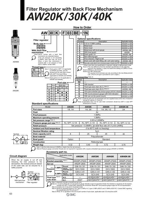
<strong>Filter</strong> <strong>Regulator</strong> <strong>with</strong> <strong>Back</strong> <strong>Flow</strong> <strong>Mechanism</strong><strong>AW20K</strong>/<strong>30K</strong>/<strong>40K</strong>AW30 K F 03 BEHow to Order1NCircuit diagram63AW<strong>40K</strong><strong>AW20K</strong>SymbolWhen the air supply is cut off andreleasing the inlet pressure to theatmosphere, the residual pressure releaseof the outlet side can be ensured for asafety purpose.With back flowmechanismSymbolStandard specifications<strong>Filter</strong> regulator<strong>Filter</strong> regulatorBody size20 30 40With back flowmechanismNote) AW10 comes <strong>with</strong> a back flowmechanism as a standard feature.If the set pressure is not exceeding0.15MPa, back flow may not occur.When a back flow mechanism isrequired <strong>with</strong> a set pressure of lessthan 0.15MPa, contact <strong>SMC</strong>.Thread typeNilN Note 1)RcF Note 2)NPTGNote 1) Drain guide is NPT 1/4 (applicableto AW<strong>30K</strong> and <strong>40K</strong>), and theexhaust port for auto drain comes<strong>with</strong> ø3/8" One-touch fitting(applicable to AW<strong>30K</strong> and AW<strong>40K</strong>).Note 2) Drain guide is G 1/4 (applicable toAW<strong>30K</strong> and AW<strong>40K</strong>).Symbol0102030406Portsize1/81/43/81/23/4ModelPort sizesFluidProof pressureMaximum operating pressureSet pressure range Note 1)Pressure gauge port size Note 2)Relief pressureAmbient and fluid temperatureNominal filtration ratingDrain capacity (cm 3 )Bowl materialBowl guardConstructionWeight (kg)Optional specificationsSymbolNote 4)1268CJNRWZDescriptionApplicable model0.02 to 0.2MPa setting<strong>AW20K</strong> to <strong>40K</strong>Metal bowl<strong>AW20K</strong> to <strong>40K</strong>Nylon bowl<strong>AW20K</strong> to <strong>40K</strong>Metal bowl <strong>with</strong> level gaugeAW<strong>30K</strong>, <strong>40K</strong>With bowl guard<strong>AW20K</strong>Drain guide 1/4AW<strong>30K</strong>, <strong>40K</strong>Non-relieving type<strong>AW20K</strong> to <strong>40K</strong><strong>Flow</strong> direction: Right to left<strong>AW20K</strong> to <strong>40K</strong>Drain cock <strong>with</strong> barb fitting: ø6 x ø4 nylon tubing AW<strong>30K</strong>, <strong>40K</strong>Name plate, caution plate for bowl, and pressure gauge in imperial units (PSI, °F) <strong>AW20K</strong> to <strong>40K</strong>∗ When more than one specification is required, indicate in alphanumeric order.Note 4) The only difference from the standard specifications is the adjustingspring for the regulator. It does not restrict the setting of 0.2MPa or more.Note 5) Without a valve function.Note 6) For NPT thread type.This product is for overseas use only according to the new MeasurementLaw. (The SI unit type is provided for use in Japan.)Accessories Note 3)SymbolNilBCDEGHDescription—With bracketFloat type auto drain (N.C.) Note 2)Float type auto drain (N.O.) Note 2)With square embedded type pressure gauge (<strong>with</strong> limit indicator) <strong>AW20K</strong> to <strong>40K</strong>With round pressure gauge (<strong>with</strong> limit indicator) <strong>AW20K</strong> to <strong>40K</strong>With set nut (for panel mount)<strong>AW20K</strong> to <strong>40K</strong><strong>AW20K</strong>1/8, 1/4AW<strong>30K</strong>1/4, 3/8AW<strong>40K</strong>1/4, 3/8, 1/2AW<strong>40K</strong>-063/4Air1.5MPa1.0MPa0.05 to 0.85MPaRc, NPT, G 1/8 Rc, NPT, G 1/8 Rc, NPT, G 1/4 Rc, NPT, G 1/4Set pressure + 0.05MPa [at relief flow rate of 0.1L/min (ANR)]–5 to 60°C (<strong>with</strong> no freezing)5µm8254545PolycarbonateOptionStandardRelieving type0.320.400.720.75Note 1) Set the inlet pressure 0.05MPa or higher than the set pressure.Note 2) Pressure gauge connection threads are not required for regulators <strong>with</strong> a square embedded type pressure gauge (<strong>AW20K</strong> to AW<strong>40K</strong>).Accessory part no.Applicable modelAccessoryNote 1)Bracket assemblySet nutNote 2)PressuregaugeFloat typeauto drainPort size20———1.0MPa0.2MPaBody size30———40—RoundSquare Note 3)embedded typeRoundSquare Note 3)embedded typeNote 5)Note 6)<strong>AW20K</strong>AW20P-270ASAR20P-260SG36-10-01GC3-10ASG36-2-01GC3-2AS—AW<strong>30K</strong>AR30P-270ASAR30P-260SG36-10-01GC3-10ASG36-2-01GC3-2ASAW<strong>40K</strong>Note 5)AD38 AD38NNote 5)AD37 AD37NAR40P-270ASAR40P-260SG46-10-02GC3-10ASG46-2-02GC3-2ASAW<strong>40K</strong>-06Note 5)AD48 AD48NNote 5)AD47 AD47NApplicable model—<strong>AW20K</strong> to <strong>40K</strong><strong>AW20K</strong> to <strong>40K</strong>AW<strong>30K</strong>, <strong>40K</strong>Note 1) Optional parts are not assembled and are supplied loose at the time of shipment(except for options C, D and E).Note 2) Applicable tube O.D for auto drain connection should be ø3/8" in case NPTthread port is chosen.AR40P-270ASAR40P-260SG46-10-02GC3-10ASG46-2-02GC3-2ASNote 5)AD48 AD48NNote 5)AD47 AD47NNote 4)N.O.N.C.AD27Note 1) Assembly includes a bracket and set nuts.Note 2) in part numbers for a round pressure gauge indicates a type of connection thread. No indication is necessary for R; however,indicate N for NPT. Contact <strong>SMC</strong> regarding the connection thread NPT and pressure gauge supply for PSI unit specifications.Note 3) Includes one O-ring and 2 mounting screws.Note 4) Minimum operating pressure: N.O. type–0.1MPa; N.C. type–0.1MPa (AD27) and 0.15MPa (AD37/47). Contact <strong>SMC</strong> regardingthe specifications for PSI unit and °F.Note 5) When “N” is specified in the end of part number of auto drain, applicable tube O.D should be ø3/8".
<strong>Filter</strong> <strong>Regulator</strong> <strong>with</strong> <strong>Back</strong> <strong>Flow</strong> <strong>Mechanism</strong> <strong>AW20K</strong>/<strong>30K</strong>/<strong>40K</strong><strong>Flow</strong> Characteristics (Representative values)<strong>AW20K</strong>Outlet pressure MPaPressure Characteristics (Representative values)<strong>AW20K</strong>AW<strong>40K</strong>Outlet pressure MPa0.60.50.40.30.20.10.25000.2200 400 600 800<strong>Flow</strong> rate L/min (ANR)AW<strong>40K</strong> 1/2Outlet pressure MPa0.60.50.40.30.20.100Set point1/41000 2000 3000<strong>Flow</strong> rate L/min (ANR)AW<strong>30K</strong>Outlet pressure MPaOutlet pressure MPa0.250.2Condition:Inlet pressure 0.7MPaAW<strong>40K</strong>-06 3/4Outlet pressure MPa0.60.50.40.30.20.10.60.50.40.30.20.1003/800 500 1000 1500<strong>Flow</strong> rate L/min (ANR)1000 2000 3000 4000<strong>Flow</strong> rate L/min (ANR)Conditions: Inlet pressure 0.7MPaOutlet pressure 0.2MPa<strong>Flow</strong> rate 20L/min (ANR)Set pointSpecific Product PrecautionsBe sure to read before handling.Refer to pages 75 through 78 forsafety instructions and F.R.L. unitprecautions.Mounting & AdjustmentWarning1. Set the regulator while checking thedisplayed values of the inlet and outletpressure gauges. Turning the knobexcessively can cause damage to theinternal parts.2. The pressure gauge included <strong>with</strong>regulators for 0.02 to 0.2MPa setting is forup to 0.2MPa use. Exceeding 0.2MPa ofpressure can damage the gauge.3. Do not use tools on the pressure regulatorknob as this may cause damage. It must beoperated manually.Caution1. Be sure to unlock the knob before adjustingthe pressure and lock it after setting thepressure.Failure to follow this procedure can causedamage to the knob and the outlet pressuremay fluctuate.• Pull the pressure regulator knob to unlock.(You can visually verify this <strong>with</strong> the "orangemark" that appears in the gap.)• Push the pressure regulator knob to lock.When the knob is not easily locked, turn itleft and right a little and then push it (whenthe knob is locked, the "orange mark", i.e.,the gap will disappear).Orange mark0.150.15000.20.30.4 0.5 0.6 0.7 0.8Inlet pressure MPa0.91000.20.30.4 0.5 0.6 0.7 0.8Inlet pressure MPa0.91AW<strong>30K</strong>AW<strong>40K</strong>-060.250.25Outlet pressure MPa0.20.15000.20.30.4 0.5 0.6 0.7 0.8Inlet pressure MPaSet point0.91Outlet pressure MPa0.20.15000.20.30.4 0.5 0.6 0.7 0.8Inlet pressure MPaSet point0.912. A knob cover is available to preventcareless operation of the knob. Refer toFeatures 1 for details.MaintenanceWarning1. Replace the element every 2 years or whenthe pressure drop becomes 0.1MPa,whichever comes first to prevent damageto the element.64
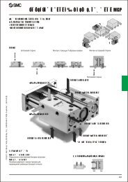
<strong>AW20K</strong>/<strong>30K</strong>/<strong>40K</strong>Operating PrincipleAA-AwFigure 1Normal<strong>SMC</strong>P U S HtoLO C KPressure indiaphragmchamberInlet pressure(IN)AeFigure 3Figure 2<strong>Back</strong> flowqPressure indiaphragmchamberInlet pressure(IN)IN(Inlet pressure)OUT IN(Outlet pressure) (Inlet pressure)rOUT(Outlet pressure)When the inlet pressure (P1) is higher than the set pressure, the check valve w closes and operates as a normal regulator (Figure 1).When the inlet pressure (P1) is shut off and released, the check valve w, opens and the pressure in the diaphragm chamber q isreleased into the inlet side (Figure 2).This lowers the pressure in the diaphragm chamber q, and the force generated by pressure regulator spring e lifts the diaphragm.Valve r opens through the stem, and the outlet pressure is released to the inlet side (Figure 3).Construction<strong>AW20K</strong> to <strong>40K</strong>AA-Aiw<strong>SMC</strong>tP U S HtoLOC KqParts listNo.12No.3BodyBonnetDescriptionDescriptionValve assemblyMaterial<strong>AW20K</strong> AW<strong>30K</strong> AW<strong>40K</strong> AW<strong>40K</strong>-06Zinc die-cast Aluminum die-cast Platinum silverPolyacetalBlackMaterialAStainless steelBrass, HNBR<strong>AW20K</strong>AW20P-090ASParts no.AW<strong>30K</strong>AW30P-090ASAW<strong>40K</strong>AW40P-090ASIN(Inlet pressure)NoteAW<strong>40K</strong>-06AW40P-090ASOUT(Outlet pressure)yeru4567865<strong>Filter</strong> elementNon-wovenDiaphragm assemblyBowl O-ringBowl assembly Note 1)Check valve assembly Note 3)fabricAF20P-060SAF30P-060SAF40P-060SNote 1) Including O-Ring. Contact <strong>SMC</strong> regarding the bowl assembly supply for PSI and °F unit specifications.Note 2) Bowl assembly for AW<strong>30K</strong> to AW60K includes a bowl guard (steel band material).Note 3) Check valve construction includes the check valve itself, check valve cover, and 2 screws.AF40P-060SWeatherability NBRNBRPCPOM, PBTAR20P-150ASC2SFP-260SC2SFAR20KP-020ASAR30P-150ASC3SFP-260SC3SF Note 2)AR20KP-020ASAR40P-150ASC4SFP-260SC4SF Note 2)AR20KP-020ASAR40P-150ASC4SFP-260SC4SF Note 2)AR20KP-020AS
O<strong>Filter</strong> <strong>Regulator</strong> <strong>with</strong> <strong>Back</strong> <strong>Flow</strong> <strong>Mechanism</strong> <strong>AW20K</strong>/<strong>30K</strong>/<strong>40K</strong>Dimensions<strong>AW20K</strong>/<strong>30K</strong>/<strong>40K</strong>Panel fitting dimensionYINWOUTHJMDUBracket(option)TNSQZCPlate thickness<strong>AW20K</strong>, <strong>30K</strong>: Max. 3.5AW<strong>40K</strong>: Max. 5VPINOUTKPressure gauge(option)OUTBSquare embedded typepressure gauge (option)Pressure gaugeport sizePort sizeMin. clearancefor maintenanceGEDrainAApplicable model<strong>AW20K</strong>With auto drain(N.C.)Metal bowlWith auto drain(N.O./N.C.)AW<strong>30K</strong>, AW<strong>40K</strong>, AC<strong>40K</strong>-06Metal bowl <strong>with</strong>Metal bowllevel gaugeWith drain guideDrain cock <strong>with</strong>barb fittingOptionalspecificationsOSBBN.O.: BlackN.C.: Greyø10One-touchfittingBBSM5 x 0.8 Barb fittingBBWidth acrossflats 171/4BApplicable tubing:T0604Model<strong>AW20K</strong>AW<strong>30K</strong>AW<strong>40K</strong>AW<strong>40K</strong>-06Port size1/8, 1/41/4, 3/81/4, 3/8, 1/23/4A40537075Standard specificationB160201239242C73869293D52597575E40577373G40558080Accessory specificationWith pressure gauge Bracket mounting size Panel mount With auto drainH63667676J2730.538.538.5K53.51.51.2M30415050N34405454P44465456Q5.46.58.58.5S15.4810.510.5T55537070U2.32.32.32.3V303135.537W28.538.542.542.5Y14192121Z6777B177242278278Model<strong>AW20K</strong>AW<strong>30K</strong>AW<strong>40K</strong>AW<strong>40K</strong>-06Port size1/8, 1/41/4, 3/81/4, 3/8, 1/23/4Optional specificationWith barb fitting With drain guide Metal bowl Metal bowl <strong>with</strong> level gaugeB—209247250B—208246249B160214251255B—23427227566
<strong>Filter</strong> <strong>Regulator</strong>AW20(K) to AW40(K)Made to Order SpecificationsContact <strong>SMC</strong> for detailed dimensions, specifications, and lead times.Made toOrdereWith Digital Pressure SwitchDigital pressure switch (ISE30---L) is supplied loose for mounting on pressure gauge connection port.SpecificationsPart number suffixModelPressureswitchSet pressure range (MPa)Set and display resolution (MPa)Power supply voltagePower consumption*Pressure gauge port size: 1/8–X465ISE30---L–0.1 to 10.00112 to 24 VDC ± 10%, Ripple (p-p) 10%or less (<strong>with</strong> power supply polarity protection)45 mA or less (70 mA or less for current output)Applicable modelsModel AW20(K) AW30(K) AW40(K) AW40(K)-06Port size 1/8, 1/4 1/4, 3/8 1/4, 3/8, 1/2 3/4NilN Note 1)F Note 2)Thread typeRcNPTG<strong>Filter</strong>regulatorAWBody sizeWith back flow mechanismNil––K With back flow machanismNote 1) Drain guide is NPT1/4 (applicableto AW30 to 40), and the exhaustport for auto drain comes <strong>with</strong>ø3/8" One-touch fitting (applicableto AW30 to 40).Note 2) Drain guide is G1/4 (applicable toAW30 to 40).Symbol0102030406Portsize1/81/43/81/23/420 30 40How to Order30 K F 03 B 1N X465 APort size20———Body size30——40—Symbol1 Note 4)268CJ Note 5)NRWZ Note 6)With digital pressure switch(Series ISE30) Note 7)Description0.02 to 0.2MPa settingMetal bowlNylon bowlMetal bowl <strong>with</strong> level gaugeWith bowl guardDrain guide 1/4Non-relieving type<strong>Flow</strong> direction: Right to leftDrain cock <strong>with</strong> barb fitting: ø6 x ø4 nylon tubingName plate and caution plate for bowl in imperial units(PSI, °F)Optional specificationsApplicable modelAW20(K) to 40(K)AW20(K) to 40(K)AW20(K) to 40(K)AW30(K), 40(K)AW20(K)AW30(K), 40(K)AW20(K) to 40(K)AW20(K) to 40(K)AW30(K), 40(K)AW20(K) to 40(K)∗ When more than one specification is required, indicate in ascending alphanumeric order.Note 4) The only difference from the standard specifications is the adjusting spring forthe regulator. It does not restrict the setting of 0.2MPa or more.Note 5) Without a valve function.Note 6) For thread type NPT.This product is for overseas use only according to the new Measurement Law.(The SI unit type is provided for use in Japan.)Option Note 3)SymbolNilBCDHDescription—With bracketFloat type auto drain (N.C.) Note 4)Float type auto drain (N.O.) Note 4)With set nut (for panel mount)Switch specificationsSymbolABCDOutput specificationsNPN outputPNP output1 to 5V output4 to 20mA outputNote 7) Optional parts are not assembled and aresupplied loose at the time of shipment.Applicable model—AW20(K) to 40(K)AW20(K) to 40(K)AW30(K), 40(K)AW20(K) to 40(K)Note 3) Optional parts are not assembled and are supplied loose at the time ofshipment (except for options C and D)Note 4) Applicable tube O.D for auto drain connection should be ø3/8" in caseNPT thread port is chosen.Note 8) Consult <strong>SMC</strong> for detailed dimensions and available attachments and options.Note 9) Refer to <strong>SMC</strong> catalogue CAT.ES100-42 for detailed specifications and instructions of digital pressure switch.67