ASR/ASQ - SMC
ASR/ASQ - SMC
ASR/ASQ - SMC

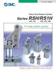
Create successful ePaper yourself
Turn your PDF publications into a flip-book with our unique Google optimized e-Paper software.
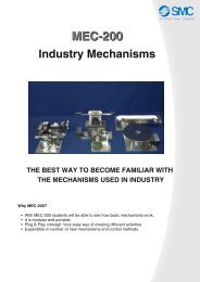
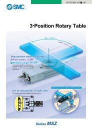
CAT.ES20-173A -UKAir Saving Valve40% reduction inair consumptionCuts air consumption byoperating the return strokeat a reduced pressure.valvePressureAir consumption reduction ratio (%)4030201000.30.1 0.15 0.2 0.25 0.3Return stroke pressure (MPa)valveFlow0.90.70.5Working stroke pressure (MPa)Working strokeReturn strokePressure ValveFlow ValveSeries <strong>ASR</strong> /Series <strong>ASQ</strong>Pressure valveFlow valve
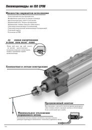
Cuts air consumption by operatingthe return stroke at a reduced pressure.Conventional valveWorking and return strokesoperated at the same pressureAir saving valveReturn stroke operatedat a reduced pressurePressurevalveFlowvalveWorking strokeWorking strokeReturn strokeReturn strokeWorking strokeReturn strokePressure valveRegulator with check valve+Speed controllerFlow valveQuick supply and exhaust valve+Speed controller(Meter-in, Meter-out)Series <strong>ASR</strong>Series <strong>ASQ</strong>Features 1
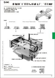
Smooth operation of working and return strokes possible.Consistent speed control achieved by preventing jerky movement of working strokes.Improved response timeOperation delay in a return stroke is reduced by the use of a quick supply and exhaust valve.Delay in returnoperation1.4Cylinder operation by conventional 2 pressure controlCylinder operation by air saving valveCylinder operation by speed controllerReturn stroke pressure0.1MPaDelay time (sec)1.21.00.80.60.40.20.0Easy pipingThe body and one-touch fitting allow 360°rotation. The sealant on the male thread isstandardized.0.2MPa0.3MPa0.1MPa0.2MPa0.3MPa0.5MPa40 50 63 80 100Cylinder bore size (mm)Cylinder speed: 200 mm/secCylinder stroke: 200 mmThe set pressure can be either fixed or variable.Fixed set pressure type(Fixed at 0.2 MPa)Pressure valveWorking strokeReturn strokeCylinder operating pressure (MPa)Working stroke Return stroke0.50.30.50.20.1Flow valveVariable set pressure type(Variable between0.1 and 0.3 MPa)Quick supply andexhaust valveAir consumptionreduction ratio (%)0172533Graduated knob23BodyJerk prevention invertical operation ofthe cylinderBalancing pressurePressure valveSpeed controllerOne-touch fittingsOther applicationsQuick air charge at theend of stroke for pressapplicationsFlow valveSpeed controllerPressure valve Flow valve Pressure valve Flow valveVariationPressure valve<strong>ASR</strong>430F-02<strong>ASR</strong>530F-02<strong>ASR</strong>530F-03<strong>ASR</strong>630F-03<strong>ASR</strong>630F-04ModelFlow valve<strong>ASQ</strong>430F-02<strong>ASQ</strong>530F-02<strong>ASQ</strong>530F-03<strong>ASQ</strong>630F-03<strong>ASQ</strong>630F-04PortsizeR1/4R1/4R3/8R3/8R1/2A knob cap isattached to thevariable setpressure type.Applicable tubing O.D. (mm)6 8 10 12Features 2
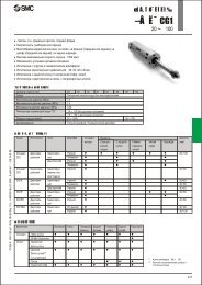
Air Saving ValvePressure ValveFlow ValveSeries <strong>ASR</strong> /Series <strong>ASQ</strong>Pressure valve / Series <strong>ASR</strong>How to Order<strong>ASR</strong>4 3 0 F 02 06 SF20Regulator with check valve and flow controlvalve integrated into a single constructionFlow valve / Series <strong>ASQ</strong>Model<strong>ASR</strong> Pressure valve<strong>ASQ</strong> Flow valve456ModelsBody size1/4 standard3/8 standard1/2 standardType3 UniversalWith One-touch fittingNilF20Applicabletubing O.D. 1)06081012Port size 1)02 R1/403 R3/804 R1/21) Please refer belowModel Table forpossible combination.With sealantOptionVariable set pressure type(0.1 to 0.3 MPa)Fixed set pressure type(0.2 MPa)6 mm8 mm10 mm12 mmPressure valve<strong>ASR</strong>430F-02<strong>ASR</strong>530F-02<strong>ASR</strong>530F-03<strong>ASR</strong>630F-03<strong>ASR</strong>630F-04ModelFlow valve<strong>ASQ</strong>430F-02<strong>ASQ</strong>530F-02<strong>ASQ</strong>530F-03<strong>ASQ</strong>630F-03<strong>ASQ</strong>630F-04Port sizeR1/4R1/4R3/8R3/8R1/2Applicable tubing O.D. (mm)6 8 10 12Pilot valve and two-way flow control valveintegrated into a single constructionSpecificationsProof pressureMaximum operating pressureSet pressure Variablerange Fixed (optional)Ambient and fluid temperatureNumber of needle rotationsApplicable tubing material1.5 MPa1.0 MPa0.1 to 0.3 MPa0.2 MPa–5 to 60°C (with no freezing)10 rotationsNylon, Soft nylon, Polyurethane1
Air Saving ValveSeries <strong>ASR</strong> / Series <strong>ASQ</strong>Effective AreaPressure Valve / Series <strong>ASR</strong>Type<strong>ASR</strong>430F-02-06S(-F20)<strong>ASR</strong>430F-02-08S(-F20)<strong>ASR</strong>430F-02-10S(-F20)<strong>ASR</strong>530F-02-06S(-F20)<strong>ASR</strong>530F-02-08S(-F20)<strong>ASR</strong>530F-02-10S(-F20)<strong>ASR</strong>530F-02-12S(-F20)<strong>ASR</strong>530F-03-06S(-F20)<strong>ASR</strong>530F-03-08S(-F20)<strong>ASR</strong>530F-03-10S(-F20)<strong>ASR</strong>530F-03-12S(-F20)<strong>ASR</strong>630F-03-10S(-F20)<strong>ASR</strong>630F-03-12S(-F20)<strong>ASR</strong>630F-04-10S(-F20)<strong>ASR</strong>630F-04-12S(-F20)Free flowmm 25.45.95.97.38.99.29.57.38.99.29.515.316.015.316.0Controlled flowmm 25.96.76.78.111.813.313.78.111.813.313.717.819.117.819.1Flow Valve / Series <strong>ASQ</strong>Type<strong>ASQ</strong>430F-02-06S(-F20)<strong>ASQ</strong>430F-02-08S(-F20)<strong>ASQ</strong>430F-02-10S(-F20)<strong>ASQ</strong>530F-02-06S(-F20)<strong>ASQ</strong>530F-02-08S(-F20)<strong>ASQ</strong>530F-02-10S(-F20)<strong>ASQ</strong>530F-02-12S(-F20)<strong>ASQ</strong>530F-03-06S(-F20)<strong>ASQ</strong>530F-03-08S(-F20)<strong>ASQ</strong>530F-03-10S(-F20)<strong>ASQ</strong>530F-03-12S(-F20)<strong>ASQ</strong>630F-03-10S(-F20)<strong>ASQ</strong>630F-03-12S(-F20)<strong>ASQ</strong>630F-04-10S(-F20)<strong>ASQ</strong>630F-04-12S(-F20)Meter-outmm 24.14.64.66.69.29.810.86.69.29.810.815.316.215.316.2Meter-inmm 24.95.55.57.810.110.811.67.810.110.811.617.118.017.118.0Operating principleWorking strokeReturn strokeCylinder movement byspeed control valvePressure, StrokePHCylindermovementPRABCPHPRPressure, StrokeDPRCylinder movementby flow valveFPHPREPHTimeTime1. The cylinder starts smoothly because jerks are prevented bymeter-in control.Jerkprevention3. To prevent delay due to the pressure gap, air is rapidlyexhausted to decrease the pressure from D to E, after whichthe piston moves at a constant speed. If a speed controller isused instead of the flow valve, exhausting air will take moretime as illustrated by line D-F, resulting in longer stop time ofthe cylinder and a consequent time loss.Quick exhaustWorking strokeReturn stroke2. When the cylinder reaches the stroke end, the quick air chargeby the flow valve rapidly increases the rear side pressure (PH)from A to B. If a speed controller is used instead of the flowvalve, charging air will take more time as illustrated by line A-C, causing delay in the pressure rise.Quick supply4. The cylinder operates at a low pressure required for a return.Low pressureoperation2
Series <strong>ASR</strong> / Series <strong>ASQ</strong>Selection and AdjustmentInstall a flow valve on the working side which requires the cylinder output and a pressure valve on the return side. The product cannot beused in cases where the same pressure is necessary for both working and return strokes.In such cases use a speed controller.Horizontal mountingLow pressure side: Pressure valveHigh pressure side: Flow valveLow pressure sidePressure valveSeries<strong>ASR</strong>Working strokeReturn strokeHigh pressure sideFlow valveSeries<strong>ASQ</strong>Refer toAdjustment Procedure 1for pressure and speed adjustment.Vertical mountingLow pressure side: Pressure valveHigh pressure side: Flow valveReturn strokeWorking strokePressure valveSeries Low pressure side<strong>ASR</strong>Flow valveSeries<strong>ASQ</strong>High pressure sideIn case the load ratio is 50% or lowerat the set pressure of the flow valve:Refer toAdjustment Procedure 1for pressure and speed adjustment.If the load ratio at the set pressure of the flow valve exceeds50%, install a dual speed controller (meter-in and meter outcontrol) on the high pressure side.Low pressure side: Pressure valveHigh pressure side: Dual speed controllerReturn strokeWorking strokePressure valveSeries Low pressure side<strong>ASR</strong>Dual speed controller(Meter-in • Meter-out)Series High pressure sideASDRefer toAdjustment Procedure 2for pressure and speed adjustment.3
Air Saving ValveSeries <strong>ASR</strong> / Series <strong>ASQ</strong>Adjustment Procedure 1Pressure adjustment1. The fixed set pressure type (-F20) does not require adjustmentbecause the pressure is fixed at 0.2 MPa for both the pressurevalve and the flow valve.2. The set pressures of the variable set pressure type pressurevalve and flow valve are adjusted with knob A and knob Brespectively. Turn the knob clockwise to increase the pressureand counterclockwise to decrease the pressure.3. The graduations 1, 2 and 3 correspond to 0.1, 0.2 and 0.3MPa respectively. Align the bottom end of the knob with thegraduated line for adjustment.Knob23Align the bottom end of theknob with the graduated line.The figure illustrates thecase in which the pressure isset at 0.2 MPa.4. Set the same pressure for the pressure valve and the flowvalve (0.2 MPa as the recommended value).5. The inlet side should be supplied with a pressure which ishigher than the set pressure by 0.1 MPa or more.6. Cap the valve after adjustment.Speed control1. The cylinder speed is adjusted with knobs C , D and E . Firsthave all the knobs fully closed and then open them graduallyfor adjustment. Turn the knob clockwise to close (decrease thespeed of the piston rod) and counterclockwise to open(increase the speed of the piston rod).2. Speed adjustment for the working strokeThe speed is adjusted with the pressure valve and the flowvalve.Open knobs C and E gradually until the required speed isachieved. Make sure that knobs C and E are opened by thesame number of rotations.Note 1) If the piston rod jerks, close knob E until the smoothoperation is achieved.3. Speed adjustment for return strokeThe speed is adjusted with the flow valve.Open knob D gradually until the required speed is achieved.4. Be sure to tighten the lock nut after adjustment.Adjustment Procedure 2Pressure adjustmentPressure Valve / Series <strong>ASR</strong>KnobCKnobA1. The fixed set pressure type (-F20) does not require adjustmentbecause the pressure is fixed at 0.2 MPa.2. The pressure at the low pressure side (return stroke side) isadjusted by the pressure valve.3. The set pressure is adjusted with knob A . Turn the knobclockwise to increase the pressure and counterclockwise todecrease the pressure.4. The graduations 1, 2 and 3 correspond to 0.1, 0.2 and 0.3MPa respectively. Align the bottom end of the knob with thegraduated line for adjustment.5. Keep the set pressure as low as possible in order to achievegood air saving effect.6. Cap the valve after adjustment.Flow Valve / Series <strong>ASQ</strong>KnobDSpeed controlKnobBEKnob1. The cylinder speed is adjusted with knobs C , F and G . Firsthave all the knobs fully closed and then open them graduallyfor adjustment. Turn the knob clockwise to close (decrease thespeed of the pistoin rod) and counterclockwise to open(increase the speed of the piston rod).2. Speed adjustment for the working strokeThe speed is adjusted with the pressure valve and the dualspeed controller.Open knobs C and G gradually until the required speed isachieved. Make sure that knobs C and G are opened by thesame number of rotations.Note 1) If the piston rod jerks, close knob G until the smoothoperation is achieved.3. Speed adjustment for return strokeThe speed is adjusted with the dual speed controller.Open knob F gradually until the required speed is achieved.4. Be sure to tighten the lock nut after adjustment.Pressure Valve / Series <strong>ASR</strong>Dual Speed Controller / Series ASDKnobCKnobAKnobFKnobG4
Series <strong>ASR</strong> / Series <strong>ASQ</strong>ConstructionPressure Valve / Series <strong>ASR</strong>Variable typeFixed type@1 @2 @5 @4 @3 @1 @2 @5 @4 @3<strong>ASR</strong>430F-02 type<strong>ASR</strong>530F-03 type<strong>ASR</strong>630F-04 type!8!9!7wq@0e!4<strong>ASR</strong>430F-02 type<strong>ASR</strong>530F-03 typeu o !3<strong>ASR</strong>630F-04 typeu o !3!8!9!7wq@0i y !0 !1 !2e!4 i !5 !6<strong>ASR</strong>530F-02 type<strong>ASR</strong>630F-03 type!7!9tq@0rParts listNo. Description1 Body A2 Body B3 Seat ring4 Body B15 Body B26 Body C7 Stopper8 Valve9 Piston10 Adjustment screw11 Knob12 Cap13 Adjustment spring5<strong>ASR</strong>530F-02 type!8 u o !3 <strong>ASR</strong>630F-03 type !8 u o !3!7!9tq@0r!4 i y !0 !1 !2 !4 i !5 !6MaterialPBTBrassBrassBrassBrassBrassStainless steelHNBR • BrassBrassBrassBrassPolypropyleneSteel wireNoteElectroless nickel platedElectroless nickel platedElectroless nickel platedElectroless nickel platedElectroless nickel platedElectroless nickel platedElectroless nickel platedZinc chromatedNo.141516171819202122232425DescriptionU sealBody CAdjustment plugNeedleKnobLock nutNote 1)U sealElbow bodySpacerNote 2)MaterialCassetteSealDrive bodyNote 3)HNBRBrassBrassBrassPBTSteelHNBRPBTPBTStainless steel • POMNBRBrassNote 1) Brass is used for the material <strong>ASR</strong>530F and <strong>ASR</strong>630F.Note 2) Not used for ø6 and ø8.Note 3) Not used for ø10 and ø12.NoteElectroless nickel platedElectroless nickel platedElectroless nickel platedElectroless nickel platedElectroless nickel plated
Air Saving ValveSeries <strong>ASR</strong> / Series <strong>ASQ</strong>Flow Valve / Series <strong>ASQ</strong>Variable typeFixed type@2 @3 @6 @5 @4@2 @3 @6 @5 @4<strong>ASQ</strong>430F-02 type<strong>ASQ</strong>530F-03 type<strong>ASQ</strong>630F-04 type!7!6!8wq@0ei<strong>ASQ</strong>430F-02 typeu<strong>ASQ</strong>530F-03 typeo<strong>ASQ</strong>630F-04 typey!5!5!3!7!2!4!6!4!1!1!8wq@0@1 !0 !9e!6 !7 @1 !0 !9 !6 !7<strong>ASQ</strong>530F-02 type<strong>ASQ</strong>630F-03 type!7!8!6tq@0riuy<strong>ASQ</strong>530F-02 type<strong>ASQ</strong>630F-03 type!5!7@1 !0 !9 !6 !7!2!8!4!6!1tq@0r@1 !0 !9 !6 !7y!5!3!4!1Parts listNo.12345678910111213DescriptionBody ABody BSeat ringBody B1Body B2Adjustment screwKnobCapAdjustment plugBody CBody D1Body D2Body D3MaterialPBTBrassBrassBrassBrassBrassBrassPolypropyleneBrassBrassBrassBrassBrassNoteElectroless nickel platedElectroless nickel platedElectroless nickel platedElectroless nickel platedElectroless nickel platedElectroless nickel platedElectroless nickel platedElectroless nickel platedElectroless nickel platedElectroless nickel platedElectroless nickel platedNo.14151617181920212223242526DescriptionPiston valveAdjustment springNeedleKnobLock nutNote 1)Lock nutNote 1)U sealU sealElbow bodySpacerNote 2)MaterialCassetteSealNote 3)Drive bodyHNBR • BrassSteel wireBrassPBTSteelSteelHNBRHNBRPBTPBTStainless steel • POMNBRBrassNote 1) Brass is used for the material <strong>ASQ</strong>530F and <strong>ASQ</strong>630F.Note 2) Not used for ø6 and ø8.Note 3) Not used for ø10 and ø12.NoteZinc chromatedElectroless nickel platedElectroless nickel platedBlack zinc chromatedElectroless nickel plated6
Series <strong>ASR</strong> / Series <strong>ASQ</strong>Flow CharacteristicsPressure Valve / Series <strong>ASR</strong> (Inlet pressure: 0.5 MPa)<strong>ASR</strong>430F <strong>ASR</strong>530F <strong>ASR</strong>630FFlow rate l/min (ANR)400300200100642Effective area mm 2Flow rate l/min (ANR)1250084Effective area mm 2Flow rate l/min (ANR)10005002015105Effective area mm 205 10Number of needle rotations05 10Number of needle rotations05 10Number of needle rotationsFlow Valve / Series <strong>ASQ</strong>Meter-out type (Inlet pressure: 0.3 MPa)<strong>ASQ</strong>430F<strong>ASQ</strong>530F<strong>ASQ</strong>630FFlow rate l/min (ANR)200100642Effective area mm 2Flow rate l/min (ANR)400300200100105Effective area mm 2Flow rate l/min (ANR)5002015105Effective area mm 205 10Number of needle rotations05 10Number of needle rotations05 10Number of needle rotationsMeter-in type (Inlet pressure: 0.5 MPa)<strong>ASQ</strong>430F<strong>ASQ</strong>530F<strong>ASQ</strong>630FFlow rate l/min (ANR)400300200100642Effective area mm 2Flow rate l/min (ANR)5001284Effective area mm 2Flow rate l/min (ANR)10005002015105Effective area mm 205 10Number of needle rotations05 10Number of needle rotations05 10Number of needle rotationsPressure Characteristics (<strong>ASR</strong>)<strong>ASR</strong>430F, <strong>ASR</strong>530F0.4Set pressure 0.3 MPa<strong>ASR</strong>630F0.4Set pressure 0.3 MPaP2: Outlet pressure0.30.20.1Set pressure 0.2 MPaSet pressure 0.1 MPaP2: Outlet pressure0.30.20.1Set pressure 0.2 MPaSet pressure 0.1 MPa000 0.1 0.2 0.3 0.4 0.5 0.6 0.7 0.8 0 0.1 0.2 0.3 0.4 0.5 0.6 0.7 0.8P1: Inlet pressureP1: Inlet pressure7
Air Saving ValveSeries <strong>ASR</strong> / Series <strong>ASQ</strong>DimensionsPressure Valve / Series <strong>ASR</strong>Variable set pressure typeFixed set pressure type (-F20)H(Width acrossflats)H(Width acrossflats)L1L2ML6øD1A2L5A1øD3TdøD1A2L5A1øD3TL1L2dMøD2øD2L6L3L4ModelNote 1)dT H D1 D2 D3<strong>ASR</strong>430F-02-06S,-F20 6<strong>ASR</strong>430F-02-08S,-F20 8 R1/4 17 18.5 20 21.5<strong>ASR</strong>430F-02-10S,-F20 10<strong>ASR</strong>530F-02-06S,-F20 6<strong>ASR</strong>530F-02-08S,-F20 818.5R1/4 21<strong>ASR</strong>530F-02-10S,-F20 1024.3 25.3<strong>ASR</strong>530F-02-12S,-F20 1220.9<strong>ASR</strong>530F-03-06S,-F20 6<strong>ASR</strong>530F-03-08S,-F20 818.5R3/8 21<strong>ASR</strong>530F-03-10S,-F20 1024.3 25.3<strong>ASR</strong>530F-03-12S,-F20 1220.9<strong>ASR</strong>630F-03-10S,-F20 1018.5R3/8 25<strong>ASR</strong>630F-03-12S,-F20 1220.929.7 30<strong>ASR</strong>630F-04-10S,-F20 1018.5R1/2 25<strong>ASR</strong>630F-04-12S,-F20 1220.929.7 30Note 6)L157.758.753.862.963.95960.862.963.95960.862.864.662.864.6Note 6)L234.935.93136.537.532.634.436.537.532.634.432.634.432.634.4Note 2)L3Note 3)L4Note 1) “d” indicates the applicable tubing O.D.Note 2) L3 is the dimension for the variable set pressure type.Note 3) L4 is the dimension for the fixed set pressure type.Note 4) A1 and A2 are reference dimensions after installation.Note 5) ∗ 1 is the weight for the variable set pressure type and ∗ 2 is that for the fixed set pressure type.Note 6) Please note, it is possible to rotate the piping port in 360°.63.767.367.386.386.345.649.249.265.565.5L5 A1 Weight (g) Note 5)L6 A2 MMAX. MIN. MAX. MIN. ∗ 1 ∗ 250.655.857.467.671.145.650.852.460.163.62325.925.927.727.744.649.85161.262.939.644.84653.755.416.818.82020.624.11718.5211718.521221718.52122212221221111141051501531431461601631531562372392572598993821271301201221371401301332192212392398
Series <strong>ASR</strong> / Series <strong>ASQ</strong>DimensionsFlow Valve / Series <strong>ASQ</strong>Variable set pressure typeFixed set pressure typeH(Width acrossflats)H(Width acrossflats)øD4øD4L8A2L7A1øD1øD3L6TL1L2dMøD2L8A2L7A1øD1øD3L5TL1L2dMøD2L3L3L4L4Note 1)Modeld<strong>ASQ</strong>430F-02-06S,-F20 6<strong>ASQ</strong>430F-02-08S,-F20 8<strong>ASQ</strong>430F-02-10S,-F20 10<strong>ASQ</strong>530F-02-06S,-F20 6<strong>ASQ</strong>530F-02-08S,-F20 8<strong>ASQ</strong>530F-02-10S,-F20 10<strong>ASQ</strong>530F-02-12S,-F20 12<strong>ASQ</strong>530F-03-06S,-F20 6<strong>ASQ</strong>530F-03-08S,-F20 8<strong>ASQ</strong>530F-03-10S,-F20 10<strong>ASQ</strong>530F-03-12S,-F20 12<strong>ASQ</strong>630F-03-10S,-F20 10<strong>ASQ</strong>630F-03-12S,-F20 12<strong>ASQ</strong>630F-04-10S,-F20 10<strong>ASQ</strong>630F-04-12S,-F20 12Note 6) Note 6)T H D1 D2 D3 D4L1 L2L3R1/4R1/4R3/8R3/8R1/217 18.5 20 21.5 19.561.662.657.765.634.935.93136.520.3 49.4 44.42118.566.6 37.524.3 24.8 20.461.7 32.623.4 53.5 48.520.963.565.634.436.52118.566.6 37.524.3 24.8 20.461.7 32.623.4 53.5 48.520.963.5 34.4252518.574.8 32.629.7 30.7 3020.976.6 34.418.574.8 32.629.7 30.7 3020.976.6 34.430.830.874.374.366.866.8Note 1) “d” indicates the applicable tubing O.D..Note 2) L5 is the dimension for the variable set pressure type.Note 3) L6 is the dimension for the fixed set pressure type.Note 4) A1 and A2 are reference dimensions after installation.Note 5) ∗ 1 is the weight for the variable set pressure type and ∗ 2 is that for the fixed set pressure type.Note 6) Please note, it is possible to rotate the piping port in 360°.9L4 Note 2)L5Note3) L7 A1 Note 4) Note 4)Weight (g) Note 5)L8MMAX. MIN. L6 MAX. MIN. MAX. MIN. A2 ∗ 1 ∗ 288.892.293.8107.9111.468.77273.686.990.450.655.857.467.671.145.650.852.460.163.62325.625.6282844.649.85161.262.939.644.84653.755.41717.9 18.5211718.51921221718.520.221222120.8222124.122136139130178181172174188191182184310312330332114117108155158149151165168159161292294312314
Safety InstructionsThese safety instructions are intended to prevent a hazardous situation and/orequipment damage. These instructions indicate the level of potential hazard bylabels of "Caution", "Warning" or "Danger". To ensure safety, be sure toobserve ISO 4414 Note 1) , JIS B 8370 Note 2) and other safety practices.Caution : Operator error could result in injury or equipment damage.Warning : Operator error could result in serious injury or loss of life.Danger : In extreme conditions, there is a possible result of serious injury or loss of life.Note 1) ISO 4414: Pneumatic fluid power — General rules relating to systems.Note 2) JIS B 8370 : Pneumatic system axiom.Warning1. The compatibility of pneumatic equipment is the responsibility of the personwho designs the pneumatic system or decides its specifications.Since the products specified here are used in various operating conditions, their compatibility for the specificsystem must be based on specifications or after analysis and/or tests to meet your specific requirements.The expected performance and safety assurance will be the responsibility of the person who has determinedthe compatibility of the system. This person should continuously review the suitability of all items specified,referring to the latest catalogue information with a view to giving due consideration to any possibility ofequipment failure when configuring a system.2. Only trained personnel should operate pneumatically operated machineryand equipment.Compressed air can be dangerous if handled incorrectly. Assembly, handing or repair of pneumatic systemsshould be performed by trained and experienced operators.3. Do not service machinery/equipment or attempt to remove components untilsafety is confirmed.1. Inspection and maintenance of machinery/equipment should only be performed after confirmation of safelocked-out control positions.2. When equipment is to be removed, confirm the safety process as mentioned above. Cut the supply pressureand electric power for this equipment and exhaust all compressed air in the system.3. Before machinery/equipment is restarted, take measures to prevent shooting-out of cylinder piston rod, etc.4. Contact <strong>SMC</strong> if the product is to be used in any of the following conditions:1. Conditions and environments beyond the given specifications, or if product is used outdoors.2. Installation on equipment in conjunction with atomic energy, railway, air navigation, vehicles, medicalequipment, food and beverages, recreation equipment, emergency stop circuits, press applications, or safetyequipment3. An application which has the possibility of having negative effects on people, property, or animals, requiringspecial safety analysis.10
Air Saving Valve PrecautionsBe sure to read before handling.1. Read the instruction manual carefully.The instruction manual should be carefully read and fullyunderstood before the product is installed and operated. Also,the manual should be kept where it can be easily referred to atany time.2. Allow space for maintenance.Allow the space necessary for maintenance and inspections.3. Tighten screws with the proper tighteningtorque.When mounting the product, tighten screws with the recommendedtorque.11WarningWarningCautionSelection1. Confirm the specifications.The products appearing in this catalog are designed for useonly in compressed air (included vacuum pressure) systems.Do not use outside the specified ranges of pressure, temperature,etc., as this may cause damage or malfunction. (Refer tospecifications.)Consult <strong>SMC</strong> if fluids other than compressed air (included vacuumpressure) are to be used.InstallationPiping1. Preparation before pipingBefore piping is connected, it should be thoroughly blown outwith air (flushing) or washed to remove chips, cutting oil andother debris from inside the pipe.3. Wrapping of sealant tapeWhen screwing together pipes, fittings, etc., be certain thatchips from the pipe threads and sealant material do not get insidethe piping.Further, when sealant tape is used, leave 1.5 to 2 thread ridgesexposed at the end of the threads.WarningAir Supply1. Types of fluidThis product is designed for use with compressed air. Contact<strong>SMC</strong> if a different type of fluid is to be used.Contact <strong>SMC</strong> regarding products for general fluids, to confirmwhich fluids can be used.2. A large amount of condensatePressurized air containing a large amount of condensate maycause malfunction of the pneumatic equipment. An air dryer orwater separator should be installed upstream from the filters.CautionAir Supply3. Drain flushing managementIf the air filter drains are not flushed regularly, the condensatewill flow downstream from the drains, resulting in malfunctionof the pneumatic equipment.In cases where drain flushing will be difficult, use of filters withauto drain is recommended.For detailed information on the quality of compressed air, referto Best Pneumatics Vol. 4.4. Types of airDo not use compressed air containing chemicals, salt, corrosivegases, synthetic oil which includes organic solvents, etc.,which may cause damage or faulty operation.WarningOperating Environment1. Do not use valves where there is direct contactwith, or in atmospheres of, corrosive gases,chemicals, salt water, water or steam.2. Provide shade in locations which receive directsunlight.3. Do not operate in locations where vibration orimpact occurs.4. Do not operate in locations where the productis exposed to direct heat radiation from a heatsource at a close distance.WarningMaintenance1. Maintenance should be performed in accordancewith the procedures in the instructionmanual.Incorrect handling can cause damage or malfunction ofmachinery and equipment, etc.2. Maintenance workCompressed air can be dangerous if handled improperly.Element replacement and other maintenance etc., should beperformed by personnel having sufficient knowledge andexperience pertaining to pneumatic equipment, while alsoadhering to the product specifications.3. Drain flushingCondensate should be flushed from the air filter and otherdrains on a regular basis.4. Pre-maintenance checksWhen the product is to be removed, be sure to shut off thesupply pressure, release compressed air in the pipelines andconfirm an atmospheric release condition before proceeding.5. Post-maintenance checksAfter mounting, repair or renovation, supply compressed airand perform suitable function and leak tests. If an audible leakis detected or equipment does not operate properly, stopoperation and confirm that mounting is correct.6. Disassembly and modification is prohibited.Do not disassemble or modify the main unit.
Pressure Valve Series <strong>ASR</strong> / Flow Valve Series <strong>ASQ</strong>Specific Product PrecautionsBe sure to read before handling.Warning1. The product cannot be used as a stop valve,of which zero leakage is required.The specifications of the product allow a certain degree ofleakage.2. Confirm whether PTFE can be used.The sealing compound contains PTFE (tetrafluoroethylene resin)powder. Make sure that it will not cause any problem in operation.3. Keep the set pressure range of the outletpressure of the pressure valve within 85%that of the inlet pressure.If the value exceeds 85%, the pressure may become unstable,affected by the fluctuation of the inlet pressure.WarningSelectionInstallation1. Confirm that the lock nut is not loose.If the lock nut is loose, there may be dangerous changes inactuator speed.2. The number of opening and closing rotationsof the needle valve and adjustment screwshould be adjusted within the range of thespecifications.Since it has a pull-out stop mechanism, it will not rotate pastthe limit. Confirm the number of rotations for the product beingused, as excessive turning of the needle will cause damage.3. To adjust the speed, start with the needle inthe completely closed position, and thenadjust by opening gradually.When the needle valve is opening, the actuator may jerksuddenly creating a dangerous situation.Moreover, the needle valve is closed by turning clockwise,and opened by turning counterclockwise. Therefore, theactuator speed is reduced by turning clockwise and increasedby turning counterclockwise.When the product is used for an actuator operating vertically,the actuator may lurch depending on the load. For theadjustment method, please refer to “Selection and Adjustment”on page 3 and 4.4. For installation and removal, tighten the bodyB by applying an appropriate wrench to thetwo opposite sides of the hexagon.Using other parts may destroy the valve. For alignment afterinstallation, rotate body A manually.5. Do not use universal type fittings at a positionwhere they are constantly rotated.The fittings may be damaged.6. The valve cannot be used if there are fluctuationsof the load.The piston rod may jerk during operation.7. In case a closed-center solenoid valve is used,switch to the center position only after pressurecharge inside the cylinder at the strokeend is completed.If the pressure charge is insufficient, the piston rod may jerkafter restart.CautionTightening Torque1. The proper tightening torque for pipe fittings is asshown in the table. As a rule, they should be tightened2 to 3 turns with a tool after first tightening by hand.Be careful not to cause damage by over-tightening.Malethread1/43/81/2Proper tightening torqueN•m12 to 1422 to 2428 to 30Handling of One-Touch FittingsCautionWidth across flatsmm172125Nominal size of adjustableangle wrench mm2002002501. Installation and Removal of Tubing for One-Touch Fittings1) Installation of tubing(1) Using tube cutters TK-1, 2 or 3, take a tube having noflaws on its periphery and cut it off at a right angle. Do notuse pinchers, nippers or scissors, etc. The tubing mightbe cut diagonally or flattened, making installationimpossible or causing problems such as disconnectionand leakage. Allow extra length for the tubing.(2) Hold the tubing and push it in slowly, inserting it securelyall the way into the fitting.(3) After inserting the tubing, pull on it lightly to confirm that itwill not come out. If it is not installed securely all the wayinto the fitting, problems such as leakage or disconnectionof the tubing can occur.2) Removal of tubing(1) Push in the release button sufficiently, pressing the collarevenly around its circumference.(2) Pull out the tubing while holding down the release buttonso that it does not pop out. If the release button is notpressed down sufficiently, there will be increased bite onthe tubing and it will become more difficult to pull it out.(3) When the removed tubing is to be used again, first cut offthe section of the tubing which has been chewed. Usingthe chewed portion of the tube as it is can cause problemssuch as leakage or difficulty in removing the tubing.CautionOperating1. The valve cannot be used if the same pressure is required forboth the working and return strokes.The pressure valve and flow valve are designed to save air bythe difference in the operating pressure.2. Install a flow valve on the working side which requires thecylinder output and a pressure valve on the return side. Thecylinder may not operate if the valves are installed on thewrong sides.Working strokeReturn strokePressure ValveSeries <strong>ASR</strong>Flow ValveSeries <strong>ASQ</strong>3. If a closed-centre, exhaust-centre, pressure-centre or perfectsolenoid valve is used and the solenoid valve is set at thecenter position, the cylinder may move to the position wherethe pressure balance and load balance are achieved.12
© DiskArt 1988EUROPEAN SUBSIDIARIES:Austria<strong>SMC</strong> Pneumatik GmbH (Austria).Girakstrasse 8, A-2100 KorneuburgPhone: +43 2262-62280, Fax: +43 2262-62285E-mail: office@smc.athttp://www.smc.atGermany<strong>SMC</strong> Pneumatik GmbHBoschring 13-15, D-63329 EgelsbachPhone: 06103-4020, Fax: 06103-402139E-mail: info@smc-pneumatik.deNetherlands<strong>SMC</strong> Pneumatics BVDe Ruyterkade 120, NL-1011 AB AmsterdamPhone: 020-5318888, Fax: 020-5318880E-mail: info@smcpneumatics.nlSlovenia<strong>SMC</strong> industrijska Avtomatika d.o.o.Grajski trg 15, SLO-8360 ZuzemberkPhone: +386 738 85240 Fax: +386 738 85249E-mail: office@smc-ind-avtom.sihttp://www.smc-ind-avtom.siBelgium<strong>SMC</strong> Pneumatics N.V./S.A.Nijverheidsstraat 20, B-2160 WommelgemPhone: 03-355-1464, Fax: 03-355-1466E-mail: post@smcpneumatics.beGreeceS. Parianopoulus S.A.7, Konstantinoupoleos Street,GR-11855 AthensPhone: 01-3426076, Fax: 01-3455578Norway<strong>SMC</strong> Pneumatics Norway A/SVollsveien 13 C, Granfos NæringsparkN-1366 LysakerTel: (47) 67 12 90 20, Fax: (47) 67 12 90 21Spain<strong>SMC</strong> España, S.A.Zuazobidea 1401015 VitoriaPhone: 945-184 100, Fax: 945-184 124E-mail: post@smc.smces.esCzech Republic<strong>SMC</strong> Industrial Automation CZ s.r.o.Hudcova 78a, CZ-61200 BrnoPhone: +420 5 414 24611, Fax: +420 5 412 18034E-mail: office@smc.czhttp://www.smc.czHungary<strong>SMC</strong> Hungary Ipari Automatizálási Kft.Budafoki ut 107-113, H-1117 BudapestPhone: +36 1 371 1343, Fax: +36 1 371 1344E-mail: office@smc-automation.huhttp://www.smc-automation.huPoland<strong>SMC</strong> Industrial Automation Polska Sp.z.o.o.ul. Konstruktorska 11A, PL-02-673 Warszawa,Phone: +48 22 548 5085, Fax: +48 22 548 5087E-mail: office@smc.plhttp://www.smc.plSweden<strong>SMC</strong> Pneumatics Sweden ABEkhagsvägen 29-31, S-141 71 HuddingePhone: 08-603 07 00, Fax: 08-603 07 10http://www.smc.nuDenmark<strong>SMC</strong> Pneumatik A/SKnudsminde 4B, DK-8300 OdderPhone: (45)70252900, Fax: (45)70252901E-mail: smc@smc-pneumatik.dkIreland<strong>SMC</strong> Pneumatics (Ireland) Ltd.2002 Citywest Business Campus,Naas Road, Saggart, Co. DublinPhone: 01-403 9000, Fax: 01-464-0500Portugal<strong>SMC</strong> Sucursal Portugal, S.A.Rua de Engº Ferreira Dias 452, 4100-246 PortoPhone: 22-610-89-22, Fax: 22-610-89-36E-mail: postpt@smc.smces.esSwitzerland<strong>SMC</strong> Pneumatik AGDorfstrasse 7, CH-8484 WeisslingenPhone: 052-396-3131, Fax: 052-396-3191E-mail: info@smc.chhttp://www.smc.chEstonia<strong>SMC</strong> Pneumatics Estonia OÜLaki 12-101, 106 21 TallinnPhone: 06 593540, Fax: 06 593541http://www.smcpneumatics.eeItaly<strong>SMC</strong> Italia S.p.AVia Garibaldi 62, I-20061Carugate, (Milano)Phone: 02-92711, Fax: 02-9271365E-mail: mailbox@smcitalia.itRomania<strong>SMC</strong> Romania srlVasile Stroescu 19, Sector 2, BucharestPhone: 01-3205111, Fax: 01-3261489E-mail: smccadm@canad.roTurkeyEntek Pnömatik San. ve Tic Ltd. Sti.Perpa Tic. Merkezi Kat: 11 No: 1625,TR-80270 Okmeydani IstanbulPhone: 0212-221-1512, Fax: 0212-221-1519Finland<strong>SMC</strong> Pneumatics Finland OYPL72, Tiistinniityntie 4, SF-02031 ESPOOPhone: 09-859 580, Fax: 09-8595 8595Latvia<strong>SMC</strong> Pneumatics Latvia SIASmerla 1-705, Riga LV-1006, LatviaPhone: 0777-94-74, Fax: 0777-94-75Russia<strong>SMC</strong> Pneumatik LLC.36/40 Sredny pr. St. Petersburg 199004Phone.:(812) 118 5445, Fax:(812) 118 5449E-mail: smcfa@peterlink.ru© DiskArtUK<strong>SMC</strong> Pneumatics (UK) LtdVincent Avenue, Crownhill,Milton Keynes, MK8 0ANPhone: 0800 1382930 Fax: 01908-555064E-mail: sales@pneumatics.co.ukhttp://www.smcpneumatics.co.ukFrance<strong>SMC</strong> Pneumatique, S.A.1, Boulevard de Strasbourg, Parc Gustave EiffelBussy Saint GeorgesF-77607 Marne La Vallee Cedex 3Phone: 01-6476 1000, Fax: 01-6476 1010LithuaniaUAB Ottensten LietuvaSavanoriu pr. 180, LT-2600 Vilnius, LithuaniaPhone/Fax: 370-2651602Slovakia<strong>SMC</strong> Priemyselná Automatizáciá, s.r.o.Námestie Martina Benku 10SK-81107 BratislavaPhone: +421 2 444 56725, Fax: +421 2 444 56028E-mail: office@smc.skhttp://www.smc.skOTHER SUBSIDIARIES WORLDWIDE:ARGENTINA, AUSTRALIA, BOLIVIA, BRASIL, CANADA, CHILE, CHINA, HONG KONG, INDIA, MALAYSIA, MEXICO, NEW ZEALAND,PHILIPPINES, SINGAPORE, SOUTH KOREA, TAIWAN, THAILAND, USA, VENEZUELAhttp://www.smceu.comhttp://www.smcworld.com<strong>SMC</strong> CORPORATION 1-16-4 Shimbashi, Minato-ku, Tokio 105 JAPAN; Phone:03-3502-2740 Fax:03-3508-2480Produced and printed by <strong>SMC</strong> European Marketing Centre 4/03Specifications are subject to change without prior noticeand any obligation on the part of the manufacturer.