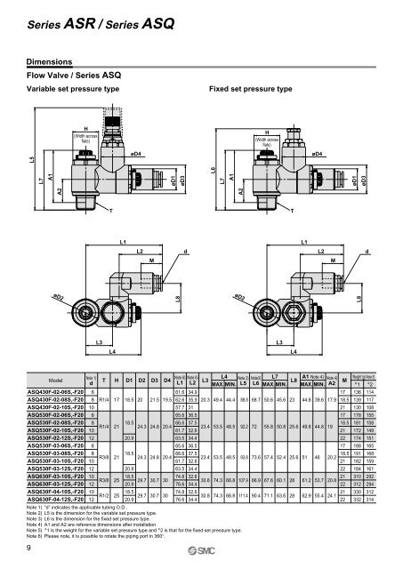
Series <strong>ASR</strong> / Series <strong>ASQ</strong>DimensionsFlow Valve / Series <strong>ASQ</strong>Variable set pressure typeFixed set pressure typeH(Width acrossflats)H(Width acrossflats)øD4øD4L8A2L7A1øD1øD3L6TL1L2dMøD2L8A2L7A1øD1øD3L5TL1L2dMøD2L3L3L4L4Note 1)Modeld<strong>ASQ</strong>430F-02-06S,-F20 6<strong>ASQ</strong>430F-02-08S,-F20 8<strong>ASQ</strong>430F-02-10S,-F20 10<strong>ASQ</strong>530F-02-06S,-F20 6<strong>ASQ</strong>530F-02-08S,-F20 8<strong>ASQ</strong>530F-02-10S,-F20 10<strong>ASQ</strong>530F-02-12S,-F20 12<strong>ASQ</strong>530F-03-06S,-F20 6<strong>ASQ</strong>530F-03-08S,-F20 8<strong>ASQ</strong>530F-03-10S,-F20 10<strong>ASQ</strong>530F-03-12S,-F20 12<strong>ASQ</strong>630F-03-10S,-F20 10<strong>ASQ</strong>630F-03-12S,-F20 12<strong>ASQ</strong>630F-04-10S,-F20 10<strong>ASQ</strong>630F-04-12S,-F20 12Note 6) Note 6)T H D1 D2 D3 D4L1 L2L3R1/4R1/4R3/8R3/8R1/217 18.5 20 21.5 19.561.662.657.765.634.935.93136.520.3 49.4 44.42118.566.6 37.524.3 24.8 20.461.7 32.623.4 53.5 48.520.963.565.634.436.52118.566.6 37.524.3 24.8 20.461.7 32.623.4 53.5 48.520.963.5 34.4252518.574.8 32.629.7 30.7 3020.976.6 34.418.574.8 32.629.7 30.7 3020.976.6 34.430.830.874.374.366.866.8Note 1) “d” indicates the applicable tubing O.D..Note 2) L5 is the dimension for the variable set pressure type.Note 3) L6 is the dimension for the fixed set pressure type.Note 4) A1 and A2 are reference dimensions after installation.Note 5) ∗ 1 is the weight for the variable set pressure type and ∗ 2 is that for the fixed set pressure type.Note 6) Please note, it is possible to rotate the piping port in 360°.9L4 Note 2)L5Note3) L7 A1 Note 4) Note 4)Weight (g) Note 5)L8MMAX. MIN. L6 MAX. MIN. MAX. MIN. A2 ∗ 1 ∗ 288.892.293.8107.9111.468.77273.686.990.450.655.857.467.671.145.650.852.460.163.62325.625.6282844.649.85161.262.939.644.84653.755.41717.9 18.5211718.51921221718.520.221222120.8222124.122136139130178181172174188191182184310312330332114117108155158149151165168159161292294312314
Safety InstructionsThese safety instructions are intended to prevent a hazardous situation and/orequipment damage. These instructions indicate the level of potential hazard bylabels of "Caution", "Warning" or "Danger". To ensure safety, be sure toobserve ISO 4414 Note 1) , JIS B 8370 Note 2) and other safety practices.Caution : Operator error could result in injury or equipment damage.Warning : Operator error could result in serious injury or loss of life.Danger : In extreme conditions, there is a possible result of serious injury or loss of life.Note 1) ISO 4414: Pneumatic fluid power — General rules relating to systems.Note 2) JIS B 8370 : Pneumatic system axiom.Warning1. The compatibility of pneumatic equipment is the responsibility of the personwho designs the pneumatic system or decides its specifications.Since the products specified here are used in various operating conditions, their compatibility for the specificsystem must be based on specifications or after analysis and/or tests to meet your specific requirements.The expected performance and safety assurance will be the responsibility of the person who has determinedthe compatibility of the system. This person should continuously review the suitability of all items specified,referring to the latest catalogue information with a view to giving due consideration to any possibility ofequipment failure when configuring a system.2. Only trained personnel should operate pneumatically operated machineryand equipment.Compressed air can be dangerous if handled incorrectly. Assembly, handing or repair of pneumatic systemsshould be performed by trained and experienced operators.3. Do not service machinery/equipment or attempt to remove components untilsafety is confirmed.1. Inspection and maintenance of machinery/equipment should only be performed after confirmation of safelocked-out control positions.2. When equipment is to be removed, confirm the safety process as mentioned above. Cut the supply pressureand electric power for this equipment and exhaust all compressed air in the system.3. Before machinery/equipment is restarted, take measures to prevent shooting-out of cylinder piston rod, etc.4. Contact <strong>SMC</strong> if the product is to be used in any of the following conditions:1. Conditions and environments beyond the given specifications, or if product is used outdoors.2. Installation on equipment in conjunction with atomic energy, railway, air navigation, vehicles, medicalequipment, food and beverages, recreation equipment, emergency stop circuits, press applications, or safetyequipment3. An application which has the possibility of having negative effects on people, property, or animals, requiringspecial safety analysis.10