2006 Geological Society of America. For permission to copy, contact ...
2006 Geological Society of America. For permission to copy, contact ...
2006 Geological Society of America. For permission to copy, contact ...
- No tags were found...

Create successful ePaper yourself
Turn your PDF publications into a flip-book with our unique Google optimized e-Paper software.
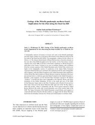
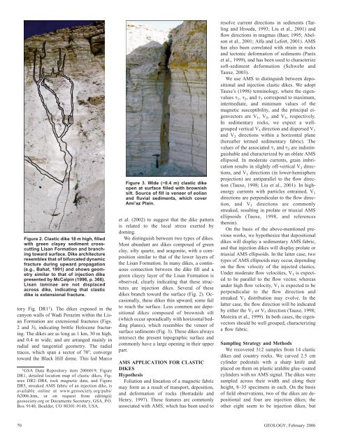
Figure 2. Clastic dike 18 m high, filledwith green clayey sediment crosscuttingLisan <strong>For</strong>mation and branching<strong>to</strong>ward surface. Dike architectureresembles that <strong>of</strong> bifurcated dynamicfracture during upward propagation(e.g., Bahat, 1991) and shows geometrysimilar <strong>to</strong> that <strong>of</strong> injection dikepresented by McCalpin (1996, p. 366).Lisan laminae are not displacedacross dike, indicating that clasticdike is extensional fracture.<strong>to</strong>ry Fig. DR1 1 ). The dikes exposed in thecanyon walls <strong>of</strong> Wadi Perazim within the Lisan<strong>For</strong>mation are extensional fractures (Figs.2 and 3), indicating brittle Holocene fracturing.The dikes are as long as 1 km, 30 m high,and 0.4 m wide, and are arranged mainly inradial and tangential geometry. The radialtraces, which span a sec<strong>to</strong>r <strong>of</strong> 70, converge<strong>to</strong>ward the Black Hill dome. This led Marco1GSA Data Reposi<strong>to</strong>ry item <strong>2006</strong>019, FigureDR1, detailed location map <strong>of</strong> clastic dikes, FiguresDR2–DR4, rock magnetic data, and FigureDR5, streaked AMS fabric <strong>of</strong> an injection dike, isavailable online at www.geosociety.org/pubs/ft<strong>2006</strong>.htm, or on request from editing@geosociety.org or Documents Secretary, GSA, P.O.Box 9140, Boulder, CO 80301-9140, USA.Figure 3. Wide (~0.4 m) clastic dikeopen at surface filled with brownishsilt. Source <strong>of</strong> fill is veneer <strong>of</strong> eolianand fluvial sediments, which coverAmi’az Plain.et al. (2002) <strong>to</strong> suggest that the dike patternis related <strong>to</strong> the local stress exerted bydoming.We distinguish between two types <strong>of</strong> dikes.Most abundant are dikes composed <strong>of</strong> greenclay, silty quartz, and aragonite, with a compositionsimilar <strong>to</strong> that <strong>of</strong> the lower layers <strong>of</strong>the Lisan <strong>For</strong>mation. In many dikes, a continuousconnection between the dike fill and agreen clayey layer <strong>of</strong> the Lisan <strong>For</strong>mation isobserved, clearly indicating that these structuresare injection dikes. Several <strong>of</strong> thesedikes branch <strong>to</strong>ward the surface (Fig. 2). Occasionally,these dikes thin upward; some fail<strong>to</strong> reach the surface. Less common are depositionaldikes composed <strong>of</strong> brownish silt(which occur sporadically with horizontal beddingplanes), which resembles the veneer <strong>of</strong>surface sediments (Fig. 3). These dikes alwaysintersect the present <strong>to</strong>pographic surface andcommonly have a large opening in their upperpart.AMS APPLICATION FOR CLASTICDIKESHypothesisFoliation and lineation <strong>of</strong> a magnetic fabricmay form as a result <strong>of</strong> transport, deposition,and deformation <strong>of</strong> rocks (Borradaile andHenry, 1997). These features are commonlyassociated with AMS, which has been used <strong>to</strong>resolve current directions in sediments (Tarlingand Hrouda, 1993; Liu et al., 2001) andflow directions in magmas (Baer, 1995; Abelsonet al., 2001; Aïfa and Lefort, 2001). AMShas also been correlated with strain in rocksand tec<strong>to</strong>nic deformation <strong>of</strong> sediments (Paréset al., 1999), and has been used <strong>to</strong> characterizes<strong>of</strong>t-sediment deformation (Schwehr andTauxe, 2003).We use AMS <strong>to</strong> distinguish between depositionaland injection clastic dikes. We adoptTauxe’s (1998) terminology, where the eigenvalues 1 , 2 , and 3 correspond <strong>to</strong> maximum,intermediate, and minimum values <strong>of</strong> themagnetic susceptibility, and the principal eigenvec<strong>to</strong>rsare V 1 ,V 2 , and V 3 , respectively.In sedimentary rocks, we expect a wellgroupedvertical V 3 direction and dispersed V 1and V 2 directions within a horizontal plane(hereafter termed sedimentary fabric). Thevalues <strong>of</strong> the associated 1 and 2 are indistinguishableand characterized by an oblate AMSellipsoid. In moderate currents, grain imbricationresults in slightly <strong>of</strong>f-vertical V 3 directions,and V 1 directions (in lower-hemisphereprojection) are antiparallel <strong>to</strong> the flow direction(Tauxe, 1998; Liu et al., 2001). In highenergycurrents with particles entrained, V 1directions are perpendicular <strong>to</strong> the flow direction,and V 3 directions are commonlystreaked, resulting in prolate or triaxial AMSellipsoids (Tauxe, 1998, and referencestherein).On the basis <strong>of</strong> the above-mentioned previousworks, we hypothesize that depositionaldikes will display a sedimentary AMS fabric,and that injection dikes will display prolate ortriaxial AMS ellipsoids. In the latter case, twotypes <strong>of</strong> AMS ellipsoids may occur, dependingon the flow velocity <strong>of</strong> the injected clastics.Under moderate flow velocities, V 1 is expected<strong>to</strong> be parallel <strong>to</strong> the flow vec<strong>to</strong>r, whereasunder high flow velocity, V 1 is expected <strong>to</strong> beperpendicular <strong>to</strong> the flow direction andstreaked V 3 distribution may evolve. In thelatter case, the flow direction will be indicatedby either the V 2 or V 3 direction (Tauxe, 1998;Moreira et al., 1999). In both cases, the eigenvec<strong>to</strong>rsshould be well grouped, characterizinga flow fabric.Sampling Strategy and MethodsWe recovered 312 samples from 14 clasticdikes and country rocks. We carved 2.5 cmcylinder pedestals with a sharp knife andplaced on them on plastic araldite glue–coatedcylinders with no AMS signal. The dikes weresampled across their width and along theirheight, 8–35 specimens in each. On the basis<strong>of</strong> field observations, two <strong>of</strong> the dikes are depositionaland four are injection dikes; theother eight seem <strong>to</strong> be injection dikes, but70 GEOLOGY, February <strong>2006</strong>