Lutron EcoSystem Programming - Lutron Lighting Installation ...
Lutron EcoSystem Programming - Lutron Lighting Installation ...
Lutron EcoSystem Programming - Lutron Lighting Installation ...
- No tags were found...
You also want an ePaper? Increase the reach of your titles
YUMPU automatically turns print PDFs into web optimized ePapers that Google loves.
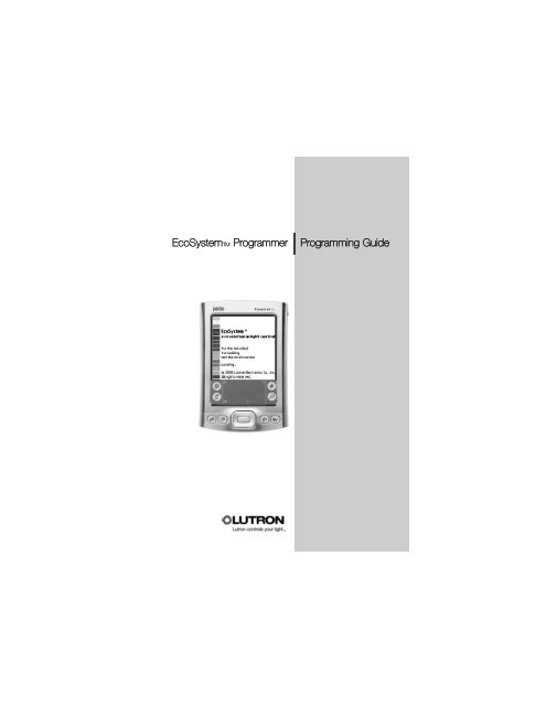
<strong>EcoSystem</strong>TM Programmer | <strong>Programming</strong> Guide
ContentsSection 1: IntroductionWhat is <strong>EcoSystem</strong>?. . . . . . . . . . . . . . . . . . . . . . . . . . . . . . . . . . . 3The <strong>EcoSystem</strong> Bus . . . . . . . . . . . . . . . . . . . . . . . . . . . . . . . . . . . 3<strong>EcoSystem</strong> <strong>Programming</strong> . . . . . . . . . . . . . . . . . . . . . . . . . . . . . . . 3Transmitting to Control Devices with IR Receivers . . . . . . . . . . . . . 4Section 2: Getting Familiar with the Programmer<strong>EcoSystem</strong> Programmer . . . . . . . . . . . . . . . . . . . . . . . . . . . . . . . . 5Logging In . . . . . . . . . . . . . . . . . . . . . . . . . . . . . . . . . . . . . . . . . . 6Making Screen Selections . . . . . . . . . . . . . . . . . . . . . . . . . . . . . . 6Control Device Icons . . . . . . . . . . . . . . . . . . . . . . . . . . . . . . . . . . 7<strong>Programming</strong> Screen Components . . . . . . . . . . . . . . . . . . . . . . . . 7Information Screens . . . . . . . . . . . . . . . . . . . . . . . . . . . . . . . . . . . 8Prompt Screens . . . . . . . . . . . . . . . . . . . . . . . . . . . . . . . . . . . . . . 8Charging the Programmer . . . . . . . . . . . . . . . . . . . . . . . . . . . . . . . 9Logging Out . . . . . . . . . . . . . . . . . . . . . . . . . . . . . . . . . . . . . . . . . 9Section 3: <strong>Programming</strong> Your SystemTypical <strong>Programming</strong> Workflow . . . . . . . . . . . . . . . . . . . . . . . . . . 10Addressing the System. . . . . . . . . . . . . . . . . . . . . . . . . . . . . . . . 12Configuring Fixture Groups . . . . . . . . . . . . . . . . . . . . . . . . . . . . . 14Setting Light Levels for Daylight Sensors . . . . . . . . . . . . . . . . . . . 16Setting Light Levels for Occupant Sensors . . . . . . . . . . . . . . . . . 18Setting Light Levels for Contact Closures . . . . . . . . . . . . . . . . . . 20Setting an Additional Timeout Period for Occupant Sensorsand Contact Closures. . . . . . . . . . . . . . . . . . . . . . . . . . . . . . . . . 22Settings Up Scenes for Wall Controls . . . . . . . . . . . . . . . . . . . . . 24Configuring Ballasts . . . . . . . . . . . . . . . . . . . . . . . . . . . . . . . . . . 26Setting a Ballast’s High End Trim . . . . . . . . . . . . . . . . . . . . . . . . . 27Setting a Ballast’s Fade Time. . . . . . . . . . . . . . . . . . . . . . . . . . . . 28
2 <strong>EcoSystem</strong>TM ProgrammerSetting a Ballast’s Emergency Level. . . . . . . . . . . . . . . . . . . . . . . 29Seasoning New Fluorescent Lamps . . . . . . . . . . . . . . . . . . . . . . 30Manually Adjusting the Light Level . . . . . . . . . . . . . . . . . . . . . . . . 31Addressing New Ballasts . . . . . . . . . . . . . . . . . . . . . . . . . . . . . . 32Replacing Ballasts . . . . . . . . . . . . . . . . . . . . . . . . . . . . . . . . . . . 33Resetting the Entire System to Factory Defaults . . . . . . . . . . . . . . 34Resetting a Ballast to Factory Defaults. . . . . . . . . . . . . . . . . . . . . 35How an <strong>EcoSystem</strong> Bus Prioritizes Inputs . . . . . . . . . . . . . . . . . . 36Index
Introduction1What is <strong>EcoSystem</strong>?<strong>EcoSystem</strong> fluorescent control systems are capable of controllingfluorescent lights through automated and manual dimming. Theautomatic fluorescent light controls include motion sensors anddaylight sensors, which monitor a space and appropriately adjust thelight to avoid wasted energy and improve the work environment. Themanual controls of the system include wall dimmers and handheldremote controls, which allow personal interaction with the lighting bythe people in the space. <strong>EcoSystem</strong> can also work together with thesecurity, HVAC, and other building management systems to providethe appropriate lighting for every situation.The <strong>EcoSystem</strong> Bus<strong>EcoSystem</strong> ballasts can be connected to one another to create asystem of up to 64 ballasts. Any infrared (IR) receiver, sensor, or wallcontrol connected to a ballast can communicate with any or allfixtures on the bus. Subsystems, called groups, are configured andprogrammed using the handheld programmer.Systems using more than one <strong>EcoSystem</strong> ballast, or ballast module,require an <strong>EcoSystem</strong> bus power supply. This component powersthe communication bus between devices, and is capable ofsupporting up to 64 ballasts or ballast modules, 32 occupantsensors, 64 wall controls, 64 infrared (IR) receivers, and 8 daylightsensors.<strong>EcoSystem</strong> <strong>Programming</strong><strong>EcoSystem</strong> is programmed using the handheld <strong>EcoSystem</strong>programmer. Using a stylus, users make onscreen selections andtransmit programming instructions via infrared, similar to a TV remote.
4 <strong>EcoSystem</strong>TM ProgrammerTransmitting to Control Devices with IR Receivers<strong>Programming</strong> information is transmitted wirelessly from the<strong>EcoSystem</strong> programmer to any sensor or control with an integratedIR receiver. When programming, stand within 8 feet (2.4 meters) ofthe sensor or control and point the top of the programmer directly atit.Regardless of what function is being performed, the system can beaccessed through any IR receiver. For example, it is not necessaryto point the programmer at the daylight sensor being programmed ifa keypad provides more convenient access.Keypads and IR receivers have LEDs that blink when programmingmessages are transmitted.If the device does not receive the signal, move closer to the deviceor adjust the angle of the programmer. It is also important to ensurethat the programmer battery is charged and has enough strength totransmit the signal to the device.NOTE: Occupant sensors do not have integrated IR receivers.
Getting Familiarwith the Programmer2This section describes how to perform basic system operations.<strong>EcoSystem</strong> ProgrammerIR portPower button(press to power on and off)Stylus(slide up to remove)Power adapterconnection
6 <strong>EcoSystem</strong>TM ProgrammerLogging InWhen the programmer is powered on, the user is prompted to entera user name and personal identification number (PIN). PINs mustinclude four to seven numbers. The default PIN is 4321.1 Press the power button on thetop of the programmer topower it on.2 When the Programmer Loginscreen displays, select yourUser Name.3 Tap the keypad with the stylusto enter your PIN, then tap.NOTE: To backspace, tap .23Making Screen SelectionsAfter logging in, the Main Menu becomes the primary navigationscreen. To select a menu function, tap its title or icon with the stylus.To make other onscreen selections, simply tap the appropriateoption.To select a menufunction, tap itstitle or icon withthe stylus.Tap to displayinformation aboutthe software
Control Device Icons<strong>Programming</strong> Guide 7The following control device icons are used on programmer screens.Daylight sensorWallstationBallastOccupant sensorIR receiverContact closure<strong>Programming</strong> Screen ComponentsThe main components of <strong>EcoSystem</strong> programming screens areidentified below.Screen nameBattery lifeTap to return tothe previousscreenDots representing majorsteps in the currentfunction (completedsteps are colored in)Tap to displaythe Main Menu
8 <strong>EcoSystem</strong>TM ProgrammerInformation ScreensInformation screens are displayed after menu functions are selected.These screens are for informational purposes only. Read theonscreen instructions and then tap to continue.SampleInformation screenTap here tocontinuePrompt ScreensPrompt screens ask the user to confirm that an appropriate actionoccurred during programming.Tap here if actiondid not happenTap here ifaction happened
Charging the Programmer<strong>Programming</strong> Guide 9To charge the <strong>EcoSystem</strong> programmer, plug the AC charger into anoutlet and connect it to the base of the programmer.Logging OutTo exit the programmer software, from the Main Menu, tapEnd Session and then Log Out.
<strong>Programming</strong>Your System3Typical <strong>Programming</strong> WorkflowFollowing is the typical workflow needed to program a new<strong>EcoSystem</strong> when it is installed. This guide includes detailedinstructions for each programming step.1 Address the system. Begin by addressing the ballasts using the<strong>EcoSystem</strong> programmer. This enables the programmer tocommunicate with the ballasts and configure their settings.2 Configure fixture groups. Next, configure the group of fixtures tobe controlled by each device (IR receiver, daylight sensor, wallcontrol, occupant sensor, or contact closure). A group can be assmall as one fixture or as large as the entire <strong>EcoSystem</strong> bus.3 Set up devices. Once fixture groups have been configured foreach control device, set custom preferences for each device.4 Configure ballast settings. To further fine-tune the system,customize the high level, fade time, and emergency settings forthe ballasts.5 Program ballasts to season new fluorescent lamps. Program theballasts to operate at full intensity before dimming. Newfluorescent lamps can have impurities. Follow the lampmanufacturer’s recommendations on lamp seasoningrequirements.After initial programming is complete, the following additionalfunctions are available to control and maintain the system:• Modify programmed settings as needed• Manually control light levels via an IR receiver• Replace existing ballasts• Address new ballasts• Season new lamps
<strong>Programming</strong> Guide 11• Reset the entire system to factory default settings• Reset a single ballast to factory default settingsRefer to the following topics for detailed procedures on how toperform each programming step.
12 <strong>EcoSystem</strong>TM ProgrammerAddressing the SystemPrior to programming, each ballast must be addressed. This enablesthe programmer to communicate with the ballasts and program theirsettings.NOTE: To address new ballasts added to an existing system, refer topage 32.1 From the Main Menu, tapBallasts and then AddressSystem.2 Tap Reset & Address NewSystem.3 Read the instructions, thentap to continue.NOTE: Occupant sensors do nothave integrated IR receivers.4 Tap to continue.Caution! System will be set tofactory defaults.5 Tap to confirm the reset.(Or tap to Cancel.)6 If all ballasts flash 3 times, tap. Otherwise, tap .NOTE: If fixtures do not flash, thesignal from the programmer didnot reach the IR control device.Refer to page 4 for details.7 Tap to address thesystem.8 Tap to begin addressing.25
14 <strong>EcoSystem</strong>TM ProgrammerConfiguring Fixture GroupsA group of fixtures must be configured for each sensor or control.By grouping multiple fixtures, lighting zones can be easily set up andchanged. Any of the grouping modes can be configured from any IRreceiver. It is not necessary to directly access the sensor beinggrouped.1 From the Main Menu, tapGrouping.2 Tap the icon for the sensor orcontrol to be configured.3 Read the instructions, thentap to continue.4 Point the programmer at anyIR control device and tapto begin communication.5 If a fixture connected to thesensor flashes and otherfixtures go to minimumbrightness, tap .NOTE: If all fixtures flash threetimes and then return to normal,no sensor was detected.6 Use the left and right arrowbuttons to scroll to the sensoryou want to group (itsconnected fixture will flash).Tap to configure theselected sensor.7 If the fixtures for this sensorgo to full brightness and otherfixtures go to minimumbrightness, tap .26
<strong>Programming</strong> Guide 158 Scroll to the desired fixture(selected fixture will flash). Tap+ to add the fixture to thegroup, or – to remove it.Repeat this step for eachfixture to be added orremoved from the group.9Select Done Grouping to exit.Or select Group AnotherReceiver to configure anothergroup.10 When done, if all fixtures go tohigh level, tap .Repeat this procedure toconfigure groups for each sensorand control.89
16 <strong>EcoSystem</strong>TM ProgrammerSetting Light Levels for Daylight SensorsTo save energy, a light level can be set for each row of fixtures in adaylight sensor group. Throughout the day, fixtures automaticallyadjust their light level based on how much daylight the space isreceiving. Light levels can be set from any IR receiver. It is notnecessary to directly access the sensor being set.NOTE: Fixtures must be grouped before setting light levels. Refer topage 14.1 From the Main Menu, tapDevice Setup and thenDaylight Sensor.2 Read the instructions, thentap to continue.3 Point the programmer at anyIR receiver and tap tobegin communication.4 If all fixtures go to minimumbrightness and a fixtureconnected to a daylight sensorflashes, tap .5 Scroll to the daylight sensor tobe set (its group fixtures willflash). Then tap toconfigure the selected sensor.6 If fixtures in row 1 of theselected sensor group go tofull brightness and all otherfixtures go to minimumbrightness, tap .By default, fixtures grouped tothe daylight sensor are inrow 1.15
<strong>Programming</strong> Guide 177 Select the daylight row to beset.8 Scroll to the desired fixture(selected fixture will flash). Tap+ to add the fixture to the row,or – to remove it. Repeat foreach fixture to be added orremoved from the row.9 Select Done.10 Set the light level to bemaintained throughout the dayfor the row.Tap the down arrow button todecrease the compensationlevel. Doing this will increasethe fixture light output.Tap the up arrow button toincrease the compensationlevel, which will decrease thefixture light output.NOTE: Changes happengradually and may not benoticeable without a light meter.Repeat this procedure to set thedaylight light levels for each rowof fixtures in each daylight sensorgroup.11 Select Done.12 Select Setup Another Sensorto set up another daylightsensor. Or select Done to exit.13 When done, if all fixtures flashand go to high level, tap .7891011
18 <strong>EcoSystem</strong>TM ProgrammerSetting Light Levels for Occupant SensorsOccupied and unoccupied light levels can be set for each fixture inan occupant sensor group. The default occupied setting is theballast’s high level; the default unoccupied setting is OFF. Occupantsensor levels can be configured from any IR receiver.1 From the Main Menu, tapDevice Setup and thenOccupant Sensor.2 Read the instructions, thentap to continue.3 Point the programmer at anyIR control device and tap .4 If all fixtures go to minimumbrightness and a fixtureconnected to a sensorflashes, tap .5 Scroll to the sensor to be set(its group fixtures will flash).Then tap to configure theselected sensor.6 If fixtures in the sensor groupgo to their occupied level andother fixtures go to minimumbrightness, tap .7 Select Set Occupied Level orSet Unoccupied Level.8 If group fixtures go to theiroccupied/unoccupied level,tap .9 Note the warning, then tapto continue.15
<strong>Programming</strong> Guide 1910 Tap the desired occupied orunoccupied light level. Ifneeded, use the arrow keys toadjust the selected levelincrementally.11 Select Done.12 Depending on what you wantto do next, select:• Continue Setup of CurrentSensor• Setup Another Sensor• Done13 When done, if all fixtures flashand go to high level, tap .Repeat this procedure to set theoccupied and unoccupied lightlevels for each occupant sensor.71011
20 <strong>EcoSystem</strong>TM ProgrammerSetting Light Levels for Contact ClosuresOccupied and unoccupied light levels can be set for each fixture ina contact closure group. The default occupied setting is the ballast’shigh level; the default unoccupied setting is OFF. Contact closurelevels can be configured from any IR receiver.1 From the Main Menu, tapDevice Setup and thenContact Closures.2 Read the instructions. Pointthe programmer at any IRcontrol device, then tap tocontinue.3 Select contact closure 1 or 2.4 If a group of fixtures go to fullbrightness and other fixturesgo to minimum brightness,tap .5 Select Set Occupied Level orSet Unoccupied Level.6 If group fixtures go to theiroccupied/unoccupied level,tap .7 Note the warning, then tapto continue.8 Tap the occupied orunoccupied light level. Ifneeded, use the arrow keys toadjust the selected levelincrementally.9 Select Done.13
<strong>Programming</strong> Guide 2110 Depending on what you wantto do next, select:• Continue Setup of CurrentSensor• Setup Another Sensor• Done11 When done, if all fixtures go tohigh level, tap .Repeat this procedure to set theoccupied and unoccupied lightlevels for each contact closuregroup.589
22 <strong>EcoSystem</strong>TM ProgrammerSetting an Additional Timeout Period for OccupantSensors and Contact Closure DevicesOccupant sensors and contact closure devices can be set up toturn fixtures off automatically after a period of inactivity. The defaulttimeout is zero seconds. Any timeout programmed into the ballastwill be in addition to that of the occupant sensor. Consult theinstallation guide for your occupant sensor to determine the totaldelay.1 From the Main Menu, tapDevice Setup and thenOccupant Sensor or ContactClosures.2 Read the instructions, thentap to continue.3 Point the programmer at anyIR control device and tapto begin communication.4 For contact closure devices,select contact closure 1 or 2.5 For occupant sensors, scrollto the sensor to be set (itsgroup of fixtures will flash).Then tap to configure theselected sensor.For contact closures, if afixture group goes to fullbrightness and other fixturesgo to minimum brightness,tap .6 If all fixtures go to minimumbrightness and a fixtureconnected to an occupantsensor flashes, tap .68
<strong>Programming</strong> Guide 237 For occupant sensors, iffixtures in the selected sensorgroup go to occupied leveland other fixtures go tominimum brightness, tap .8 Select Set Timeout.9 Note the warning, then tapto continue.10 Select the number of minutesof inactivity after which thefixture group will turn off.11 Select Done.12 Depending on what you wantto do next, select:• Continue Setup of CurrentSensor• Setup Another Sensor• Done13 When done, if all fixtures flashand then go to high level, tap.Repeat this procedure to set atimeout for each occupant sensorand contact closure device.1011
24 <strong>EcoSystem</strong>TM ProgrammerSetting Up Scenes for Wall ControlsWall controls can be set up to activate scenes (preset light levels). Adifferent scene can be configured for each button on the control.1 From the Main Menu, tapDevice Setup and thenIR Receiver/Wall Control.2 Read the instructions, thentap to continue.3 Point the programmer at anyIR receiver and tap tobegin communication.4 If all fixtures go to minimumbrightness and a fixtureconnected to a wall controlflashes, tap .5 Scroll to the wall control to beset (its group fixtures will flash).Tap to configure theselected control.6 If fixtures for this control go totheir scene 1 level, tap .7 Select the number of thescene to be set (scene 1matches the first button on thecontrol, scene 2 matches thesecond button, and so on).8 Scroll to the desired fixture(selected fixture will flash).Adjust the scene level up ordown.Repeat for each scene on thecontrol.15789
<strong>Programming</strong> Guide 259 Select Done.10 Select Setup Another Controlto set scenes for another wallcontrol. Or select Done toexit.11 When done, if all fixtures go tohigh level, tap .Repeat this procedure to set thescene levels for each IR receiverand wall control.10
26 <strong>EcoSystem</strong>TM ProgrammerConfiguring BallastsThe factory default settings for ballasts are: high level = 100%,emergency setting = 100%, and fade time = 2 seconds. Each ofthese settings can be customized to meet specific lighting needs.1 From the Main Menu, tapBallasts and then Configure1Ballast.2 Read the instructions, thentap to continue.3 Point the programmer at anyIR control device, then tapto begin communication.4 If the fixture connected to thecontrol device flashes andother fixtures go to minimumbrightness, tap .5 Scroll to a specific ballast (itsfixture will flash). Tap toselect it.5- OR --OR-To configure all the ballasts,select Configure All Ballasts.6 If selected ballasts go to fullbrightness and other fixturesgo to minimum brightness, tap.Refer to the following topics to:• Set high end trim• Set the fade time• Set the emergency level• Season lamps
Setting a Ballast’s High End Trim<strong>Programming</strong> Guide 27A ballast’s high end trim setting controls the maximum light level for adimming fixture. The factory default high level = 100%. This settingcan be customized to meet specific lighting needs.1 From the Configure Menu, tapSet High End Trim.NOTE: For procedures on how toto select one or all ballasts andthen display the Configure menu,refer to page 26.2 Tap to begin setup.3 If selected ballasts flash andgo to their high level, tap .4 Tap a light level. Then, ifneeded, use the arrow keys toadjust the selected levelincrementally.5 Tap when done.6 If the ballast(s) flash once, tap.7 Depending on what you wantto do next, select:• Continue Configuration ofCurrent Ballast(s)• Configure DifferentBallast(s)• Done8 When done, if the lastconfigured ballast(s) flash andgo to their high level, tap .145
28 <strong>EcoSystem</strong>TM ProgrammerSetting a Ballast’s Fade TimeFade time is the number of seconds it takes for a ballast to fadewhen dimmed. The default fade time = 2 seconds. This setting canbe customized as needed.1 From the Configure Menu, tapSet Fade Time.NOTE: For procedures on how toto select one or all ballasts and1then display the Configure menu,refer to page 26.2 Tap to begin setup.3 If selected ballasts flash andgo to their high level, tap .4 Tap a fade time, then tap .5 If the ballast(s) flash once,tap .6 Depending on what you wantto do next, select:• Continue Configuration ofCurrent Ballast(s)4• Configure DifferentBallast(s)• Done7 When done, if the lastconfigured ballast(s) flash andgo to their high level, tap .
Setting a Ballast’s Emergency Level<strong>Programming</strong> Guide 29The emergency setting controls a ballast’s light level in case of anemergency (for example, a power outage or fire). The defaultemergency setting is the ballast’s high level.1 From the Configure Menu, tapSet Emergency Level.NOTE: For procedures on how toto select one or all ballasts andthen display the Configure menu,refer to page 26.2 Tap to begin setup.3 If selected ballasts flash andgo to their emergency level,tap .4 Tap an emergency light level,then tap .NOTE: The intensity will changeas you make your selection. IfUnaffected, the ballast’s light levelwill not change in an emergency.5 Depending on what you wantto do next, select:• Continue Configuration ofCurrent Ballast(s)• Configure DifferentBallast(s)• Configuration Done6 When done, if the lastconfigured ballast(s) flash andgo to their high level, tap .14
30 <strong>EcoSystem</strong>TM ProgrammerSeasoning New Fluorescent LampsNew fluorescent lamps can have impurities in them that lampmanufacturers cannot eliminate completely. <strong>Lutron</strong> recommends thatlamps be operated at full intensity for 100 hours before dimming to“season” or neutralize the harmful effects of these impurities.When a system is first installed, program ballasts to season all newlamps. As lamps are added or replaced, program the seasoningprocess only for those specific ballasts.1 From the Configure Menu, tapLamp Seasoning.NOTE: For procedures on how toto select one or all ballasts andthen display the Configure menu,refer to page 26.2 Select Start Lamp Seasoning.Otherwise, select CancelLamp Seasoning.NOTE: To temporarily pause theseasoning process (e.g., to makeprogramming adjustments), selectPause Lamp Seasoning.3 If selected ballast(s) flash andgo to their high level, tap .4 Depending on what you wantto do next, select:• Continue Configuration ofCurrent Ballast(s)• Configure DifferentBallast(s)• Done5 When done, if the lastconfigured ballast(s) flash,tap .12
Manually Adjusting the Light Level<strong>Programming</strong> Guide 31The light level can be manually adjusted for all fixtures in an IRreceiver group. The adjusted light level remains in effect until one ofthe following occurs:• An emergency situation occurs• A daylight sensor lowers the fixture to compensate for naturallighting• The room becomes unoccupied, or• A user manually adjusts the level again1 From the Main Menu, tap<strong>Lighting</strong> Control.2 Read the instructions, thentap to continue.3 Point the programmer at theIR receiver whose groupfixture(s) are to be adjusted,then tap a light level.4 If needed, use the arrow keysto adjust the selected levelincrementally up or down.5 Tap Main Menu to exit.134
32 <strong>EcoSystem</strong>TM ProgrammerAddressing New BallastsIf new ballasts are added to an existing system, the ballasts must beaddressed using the <strong>EcoSystem</strong> programmer. This enables theprogrammer to communicate with the ballasts and program theirsettings.NOTES:To address all ballasts (for example, when a new system is installed),refer to page 12.To address a replacement ballast, refer to page 33.1 From the Main Menu, tapBallasts and then AddressSystem.2 Tap Address New Ballasts.3 Read the instructions, thentap to continue.4 Confirm that ballasts arepowered, then point theprogrammer at any IR controldevice and tap to beginaddressing.5 If all fixtures flash, tap .Fixtures will go to minimumbrightness as they areaddressed.6 If all fixtures are at minimumlevel, tap .Caution! Do not tap until allfixtures flash and are at theirminimum level.7 If all fixtures go to their highlevel, tap .25
<strong>Programming</strong> Guide 33Replacing BallastsIf a ballast needs to be replaced, enter the serial numbers from theold and new balast into the programmer. All settings will be appliedto the new ballast and the need for reprogramming is eliminated.1 From the Main Menu, tapBallasts and then ReplaceBallast.2 Read the instructions, thentap to continue.3 Point the programmer at anyIR control device, then tap .4 If fixtures for a receiver flashand others go to minimumbrightness, tap .5 Use the keypad to enter theserial number of the old(replaced) ballast, then tap .NOTE: To backspace, tap .6 Enter the serial number of thenew ballast. Then tap .7 If the old and new serialnumbers are entered correctly,tap .8 If the new ballast flashes andgoes to its high level, tap .9 Select Done ReplacingBallasts to exit. Or selectReplace Another Ballast toenter additional serialnumbers.10 When done, if all ballasts flashand go to their high level,tap .567
34 <strong>EcoSystem</strong>TM ProgrammerResetting the Entire System to Factory DefaultsIf needed, all <strong>EcoSystem</strong> ballasts can be reset to their factorydefaults.1 From the Main Menu, tapBallasts and then ResetSystem.2 To reset all ballasts, tapReset Entire System.3 Read the instructions, thentap to continue.NOTE: To reset a single ballast,refer to page 35.Caution! Resetting ballastsdeletes their programmed settingsand returns them to their factorydefaults.4 Tap to confirm the reset.(Or tap to Cancel.)5 If all ballasts flash 3 times,tap .6 If the reset ballast(s) flash 3times, tap .24
Resetting a Ballast to Factory Defaults<strong>Programming</strong> Guide 35If needed, a single ballast can be reset to its factory default settings.1 From the Main Menu, tapBallasts and then ResetSystem.2 Tap Reset One Ballast.NOTE: To reset the entire system,refer to page 34.3 Point the programmer at anyIR control device and tapto begin.4 If the fixture with an IR receiveror wall control flashes andother fixtures go to minimumbrightness, tap .5 Scroll to find the ballast to bereset (its fixture will flash). Thentap to reset it.Caution! Resetting a ballastdeletes its programmed settingsand returns it to the factorydefaults.6 Tap to confirm the reset.(Or tap to Cancel.)7 If the reset ballast flashes 3times and then all fixtures goto high level, tap .256
36 <strong>EcoSystem</strong>TM ProgrammerHow an <strong>EcoSystem</strong> Bus Prioritizes InputsWhen programming a system, it is important to understand how theballasts prioritize inputs:1. Emergency command (typically lights to full on). The ballast’s firstpriority is to ensure that no emergency exists in the building. If anemergency exists, all emergency fixtures are automatically set totheir emergency level and all manual lighting adjustments areignored. If an emergency does not exist, the ballast proceeds tothe next level of priority.2. <strong>Programming</strong> commands. The second priority is to respond to auser programming the ballast. If programming commands arebeing sent, the ballast responds to the commands, but ignoresany sensor or control device input. If no programming commandsare being sent, the next priority is queued.3. Occupant sensor input. The third priority is input from occupantsensors. If no person is in the room, fixtures go to theirunoccupied setting and all other sensor and control device inputsare ignored. If someone is in the room the ballast checks the nextpriority.4. Daylight sensor input. The fourth priority is input from daylightsensors. The daylight sensors are checked to set the “high level"or the maximum light level the ballasts can be manually set to.5. Personal control through IR remote or wall control. After checkingthe daylight sensor, the ballast waits for a manual control changecreated by a user dimming the lights up or down with a wallcontrol or IR remote.
IndexAaddressing the systemaddressing a new system 12addressing new ballasts 32overview 10BBack option 7ballastsaddressing a new system 12addressing new ballasts 32configuring 10, 26connecting to bus 3icon 7replacing 33resetting a single ballast 35resetting the entire system 34seasoning new lamps 10, 30serial numbers 33setting the emergency level 29setting the fade time 28setting the high end trim 27batterybattery life 7charging 4, 9bus power supply 3Cconfiguring ballastsoverview 10setting the emergency level 29setting the fade time 28setting the high end trim 27configuring fixture groups 14contact closuresconfiguring fixture groups 14icon 7setting light levels 20setting timeouts 22control devicesconfiguring fixture groups 10,14contact closures 20, 22daylight sensors 16icons 7occupant sensors 18, 22transmitting to 4wall controls 24Ddaylight level 16daylight sensorsconfiguring fixture groups 14icon 7setting the daylight level 16
38 <strong>EcoSystem</strong>TM Programmerdevice setupcontact closures 22daylight sensors 16occupant sensors 18, 22overview 10wall controls 24E<strong>EcoSystem</strong>basic operations 5overview 3priority of inputs 36programming workflow 10<strong>EcoSystem</strong> bus 3emergency level 29, 36Ffade time 28fixture groups. See groupingfixturesGgrouping fixturesoverview 10procedure 14Hhigh end trim 27Iicons 7Information screens 8inputs to <strong>EcoSystem</strong> 36IR receiversconfiguring fixture groups 14icon 7Llamps, seasoning 10, 30light levelsdaylight 16emergency 29, 36manually adjusting 31occupied 18, 20scenes 24unoccupied 18, 20logging in 6logging out 9MMain Menu 6manual lighting adjustments 31Ooccupant sensorsconfiguring fixture groups 14icon 7setting light levels 18setting timeouts 22occupied light level 18PPIN 6power button 5power supply 3
<strong>Programming</strong> Guide 39programmercharging 9power button 5transmitting 4programming workflow 10prompt screens 8Rreplacing ballasts 33resetting a single ballast 35resetting the entire system 34Sscenes 24screensBack option 7Information screens 8making selections 6prompt screens 8screen components 7viewing battery life 7seasoning new lamps 10, 30serial numbers 33stylus 5, 6Ttimeouts 22Uunoccupied lighting levels 18Wwall controlsconfiguring fixture groups 14setting up scenes 24
Limited Warranty(Valid only in U.S.A., Canada, Puerto Rico, and the Caribbean.)For a period of one year from the date of purchase, and subject to the exclusions and restrictions described below,<strong>Lutron</strong> warrants each new unit to be free from manufacturing defects. <strong>Lutron</strong> will, at its option, either repair thedefective unit or issue a credit equal to the purchase price of the defective unit to the Customer against thepurchase price of comparable replacement part purchased from <strong>Lutron</strong>. Replacements for the unit provided by<strong>Lutron</strong> or, at its sole discretion, an approved vendor may be new, used, repaired, reconditioned, and/or made by adifferent manufacturer. If the unit is commissioned by <strong>Lutron</strong> or a <strong>Lutron</strong> approved third party as part of a <strong>Lutron</strong>commissioned lighting control system, the term of this warranty will be extended, and any credits against the cost ofreplacement parts will be prorated, in accordance with the warranty issued with the commissioned system, exceptthat the term of the unit's warranty term will be measured from the date of its commissioning.EXCLUSIONS AND RESTRICTIONSThis Warranty does not cover, and <strong>Lutron</strong> and its suppliers are not responsible for: Damage, malfunction orinoperability diagnosed by <strong>Lutron</strong> or a <strong>Lutron</strong> approved third party as caused by normal wear and tear, abuse,misuse, incorrect installation, neglect, accident, interference or environmental factors, such as (a) use of incorrectline voltages, fuses or circuit breakers; (b) failure to install, maintain and operate the unit pursuant to the operatinginstructions provided by <strong>Lutron</strong> and the applicable provisions of the National Electrical Code and of the SafetyStandards of Underwriter's Laboratories; (c) use of incompatible devices or accessories; (d) improper or insufficientventilation; (e) unauthorized repairs or adjustments; (f) vandalism; or (g) an act of God, such as fire, lightning,flooding, tornado, earthquake, hurricane or other problems beyond <strong>Lutron</strong>'s control. On-site labor costs to diagnoseissues with, and to remove, repair, replace, adjust, reinstall and/or reprogram the unit or any of its components.Equipment and parts external to the unit, including those sold or supplied by <strong>Lutron</strong> (which may be covered by aseparate warranty).The cost of repairing or replacing other property that is damaged when the unit does not work properly, even if thedamage was caused by the unit.Except AS EXPRESSLY PROVIDED IN this warranty, THERE ARE NO EXPRESS OR IMPLIED WARRANTIESOF ANY TYPE, INCLUDING ANY IMPLIED WARRANTIES OF FITNESS FOR A PARTICULAR PURPOSE ORMERCHANTABILITY. LUTRON DOES NOT WARRANT THAT THE UNIT WILL OPERATE WITHOUTINTERRUPTION OR BE ERROR FREE. NO LUTRON AGENT, EMPLOYEE OR REPRESENTATIVE HAS ANYAUTHORITY TO BIND LUTRON TO ANY AFFIRMATION, REPRESENTATION OR WARRANTY CONCERNINGTHE UNIT. UNLESS AN AFFIRMATION, REPRESENTATION OR WARRANTY MADE BY AN AGENT,EMPLOYEE OR REPRESENTATIVE IS SPECIFICALLY INCLUDED HEREIN, OR IN STANDARD PRINTEDMATERIALS PROVIDED BY LUTRON, IT DOES NOT FORM A PART OF THE BASIS OF ANY BARGAINBETWEEN LUTRON AND CUSTOMER AND WILL NOT IN ANY WAY BE ENFORCEABLE BY CUSTOMER.IN NO EVENT WILL LUTRON OR ANY OTHER PARTY BE LIABLE FOR EXEMPLARY, CONSEQUENTIAL,INCIDENTAL OR SPECIAL DAMAGES (INCLUDING, BUT NOT LIMITED TO, DAMAGES FOR LOSS OFPROFITS, CONFIDENTIAL OR OTHER INFORMATION, OR PRIVACY; BUSINESS INTERRUPTION; PERSONALINJURY; FAILURE TO MEET ANY DUTY, INCLUDING OF GOOD FAITH OR OF REASONABLE CARE;NEGLIGENCE, OR ANY OTHER PECUNIARY OR OTHER LOSS WHATSOEVER), NOR FOR ANY REPAIRWORK UNDERTAKEN WITHOUT LUTRON'S WRITTEN CONSENT arising out of or in any way related to theinstallation, deinstallation, use of or inability to use THE unit or otherwise under or in connection with anyprovision of this warranty, or any agreement incorporating this warranty, even in the event of the fault, tort(including negligence), strict liability, breach of contract or breach of warranty of <strong>Lutron</strong> or any supplier,and even if <strong>Lutron</strong> or any OTHER PARTY was advised of the possibility of such damages.Notwithstanding any damages that Customer might incur for any reason whatsoever (including, withoutlimitation, all direct damages and all damages LISTED above), the entire liability of <strong>Lutron</strong> and of all OTHERPARTIES under this Warranty ON ANY CLAIM FOR DAMAGES ARISING OUT OF OR IN CONNECTION WITHTHE MANUFACTURE, SALE, INSTALLATION, DELIVERY, USE, REPAIR, OR REPLACEMENT OF THE UNIT, orany Agreement incorporating this Warranty, and Customer's SOLE remedy for the foregoing, will be limitedto the amount paid to <strong>Lutron</strong> by Customer for the unit. The foregoing limitations, exclusions anddisclaimers will apply to the maximum extent ALLOWed by applicable law, even if any remedy fails itsessential purpose.TO MAKE A WARRANTY CLAIMTo make a warranty claim, promptly notify <strong>Lutron</strong> within the warranty period described above by calling the <strong>Lutron</strong>Technical Support Center at (800) 523-9466. <strong>Lutron</strong>, in its sole discretion, will determine what action, if any, isrequired under this warranty. To better enable <strong>Lutron</strong> to address a warranty claim, have the unit's serial and modelnumbers available when making the call. If <strong>Lutron</strong>, in its sole discretion, determines that an on-site visit or otherremedial action is necessary, <strong>Lutron</strong> may send a <strong>Lutron</strong> Services Co. representative or coordinate the dispatch of arepresentative from a <strong>Lutron</strong> approved vendor to Customer's site, and/or coordinate a warranty service call betweenCustomer and a <strong>Lutron</strong> approved vendor.U.S. and foreign patent(s) pending.<strong>Lutron</strong> is a registered trademark of <strong>Lutron</strong> Electronics Co., Inc. <strong>EcoSystem</strong> is a trademark of <strong>Lutron</strong> Electronics Co.,Inc. National Electric Code and NEC are registered trademarks of the National Fire Protection Association, Quincy,Massachusetts. © 2006 <strong>Lutron</strong> Electronics Co., Inc.
www.lutron.com<strong>Lutron</strong> Electronics Co., Inc.7200 Suter RoadCoopersburg, PA 18036-1299World Headquarters +1.610.282.3800Technical Support Center 1.800.523.9466Customer Service 1.888.LUTRON1US and Foreign Patents Pending©6/2006 <strong>Lutron</strong> Electronics Co., Inc. | Made and printed in the U.S.A. | P/N 032170


