TRC-SFD-1-06 - Tribology Group - Texas A&M University
TRC-SFD-1-06 - Tribology Group - Texas A&M University
TRC-SFD-1-06 - Tribology Group - Texas A&M University

Create successful ePaper yourself
Turn your PDF publications into a flip-book with our unique Google optimized e-Paper software.
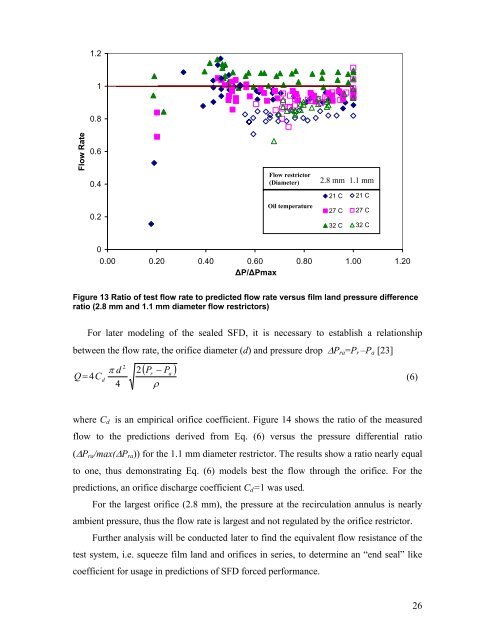
1.210.8Flow Rate0.60.40.2Flow restrictor(Diameter)Oil temperature21 C2.827 mm C21 C27 32 C32 C1.1 mm21 C27 C32 C00.00 0.20 0.40 0.60 0.80 1.00 1.20ΔP/ΔPmaxFigure 13 Ratio of test flow rate to predicted flow rate versus film land pressure differenceratio (2.8 mm and 1.1 mm diameter flow restrictors)For later modeling of the sealed <strong>SFD</strong>, it is necessary to establish a relationshipbetween the flow rate, the orifice diameter (d) and pressure drop ΔP ra =P r –P a [23]Q = 4Cd( P − P )2π d 2r4 ρa(6)where C d is an empirical orifice coefficient. Figure 14 shows the ratio of the measuredflow to the predictions derived from Eq. (6) versus the pressure differential ratio(ΔP ra /max(ΔP ra )) for the 1.1 mm diameter restrictor. The results show a ratio nearly equalto one, thus demonstrating Eq. (6) models best the flow through the orifice. For thepredictions, an orifice discharge coefficient C d =1 was used.For the largest orifice (2.8 mm), the pressure at the recirculation annulus is nearlyambient pressure, thus the flow rate is largest and not regulated by the orifice restrictor.Further analysis will be conducted later to find the equivalent flow resistance of thetest system, i.e. squeeze film land and orifices in series, to determine an “end seal” likecoefficient for usage in predictions of <strong>SFD</strong> forced performance.26