

Sloan ECOS Flushometers - Sloan Valve Company
Sloan ECOS Flushometers - Sloan Valve Company
Sloan ECOS Flushometers - Sloan Valve Company

You also want an ePaper? Increase the reach of your titles
YUMPU automatically turns print PDFs into web optimized ePapers that Google loves.
Sensor<br />
<strong>Flushometers</strong><br />
21<br />
22A<br />
16<br />
21<br />
22<br />
22A<br />
17<br />
2<br />
22<br />
22A<br />
FLEX TUBE DIAPHRAGM ASSEMBLY<br />
1<br />
12<br />
5<br />
6<br />
7<br />
9<br />
8A<br />
20<br />
4<br />
3<br />
10<br />
21<br />
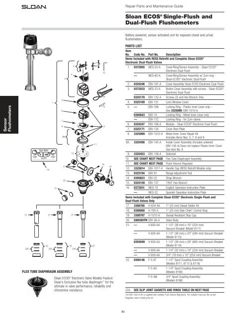
<strong>Sloan</strong> <strong>ECOS</strong> ® Electronic <strong>Valve</strong> Models Feature<br />
<strong>Sloan</strong>’s Exclusive flex tube diaphragm for the<br />
ultimate in valve performance, reliability and<br />
chloramine resistance.<br />
22<br />
11<br />
15<br />
14<br />
13<br />
8<br />
18<br />
19<br />
80<br />
Repair Parts and Maintenance Guide<br />
<strong>Sloan</strong> <strong>ECOS</strong> ® Single-Flush and<br />
Dual-Flush <strong>Flushometers</strong><br />
Battery powered, sensor activated unit for exposed closet and urinal<br />
flushometers.<br />
PARTS LIST<br />
Item<br />
No. Code No. Part No. Description<br />
Items Included with RESS Retrofit and Complete <strong>Sloan</strong> <strong>ECOS</strong> ®<br />
Electronic Dual-Flush <strong>Valve</strong>s<br />
1. 0372055 WES-55-A Cover/Ring/Sensor Assembly - <strong>Sloan</strong> <strong>ECOS</strong> ®<br />
Electronic Dual-Flush<br />
— WES-60-A Cover/Ring/Sensor Assembly w/ Zurn ring -<br />
<strong>Sloan</strong> <strong>ECOS</strong> ® Electronic Dual-Flush<br />
2. 0325246 EBV-191-A Cover Assembly <strong>Sloan</strong> <strong>ECOS</strong> Electronic Dual-Flush<br />
3. 0372033 WES-23-A Button Cover Assembly with screws - <strong>Sloan</strong> <strong>ECOS</strong> ®<br />
Electronic Dual-Flush<br />
0325170 EBV-132-A Screws (2) and Hex Wrench Only<br />
4. 0325169 EBV-131 Lens Window Cover<br />
5. — EBV-168 Locking Ring - Plastic inner cover only –<br />
Use 3325089, EBV-1010-A<br />
0305843 EBV-14 Locking Ring - Metal inner cover only<br />
— EBV-172 Locking Ring - for Zurn valves<br />
6. 0325247 EBV-196-A Module - <strong>Sloan</strong> <strong>ECOS</strong> ® Electronic Dual-Flush<br />
7. 0325171 EBV-134 Cover Rest Plate<br />
8. 3325089 EBV-1010-A Metal Inner Cover Repair Kit<br />
Includes Items Nos. 5, 7, 8 and 9<br />
8A. 3325456 EBV-145-A Inside Cover Assembly (includes solenoid<br />
EBV-136-A) Does not replace Plastic Inner Cover.<br />
Use Item No. 8<br />
9. 3325453 EBV-136-A Solenoid<br />
10. SEE CHART NEXT PAGE Flex Tube Diaphragm Assembly<br />
11. SEE CHART NEXT PAGE Flush Volume Regulator<br />
12. 3325814 EBV-1017-A Handle Cap (RESS Retrofit Models only)<br />
13. 0325194 EBV-91 Range Adjustment Tool<br />
14. 0305823 EBV-22 Strap Wrench<br />
15. 0325159 EBV-137 7/64" Hex Wrench<br />
16. 0372031 WES-19 English Operation Instruction Plate<br />
— WES-22 Spanish Operation Instruction Plate<br />
Items Included with Complete <strong>Sloan</strong> <strong>ECOS</strong> ® Electronic Single-Flush and<br />
Dual-Flush <strong>Valve</strong>s Only<br />
17. 3308785 H-634-AA 1" (25 mm) Sweat Solder Kit<br />
18. 0388000 H-700-A 1" (25 mm) Bak-Chek ® Control Stop<br />
19. 3308797 H-1010-A Vandal Resistant Stop Cap<br />
20. 0305381PK EBV-36-A <strong>Valve</strong> Body<br />
21. — V-600-AA 1-1/2" (38 mm) x 10" (254 mm)<br />
Vacuum Breaker (Model 8111)<br />
— V-600-AA 1-1/2" (38 mm) x 23" (584 mm) Vacuum Breaker<br />
(Model 8115)<br />
0393049 V-600-AA 1-1/2" (38 mm) x 26" (660 mm) Vacuum Breaker<br />
(Model 8116)<br />
— V-600-AA 1-1/4" (32 mm) x 10" (254 mm) Vacuum Breaker<br />
— V-600-AA 3/4" (19 mm) x 10" (254 mm) Vacuum Breaker<br />
22. 0306146 F-5-AT 1-1/2" Spud Coupling Assembly<br />
(Models 8111, 8115 & 8116)<br />
F-5-AU 1-1/4" Spud Coupling Assembly<br />
(Models 8180)<br />
F-5-AW 3/4" Spud Coupling Assembly<br />
(Models 8186)<br />
22A. SEE SLIP JOINT GASKETS AND RINGS TABLE ON NEXT PAGE<br />
The EBV-1020-A Kit is supplied with multiple Flush Volume Regulators. The installer must use the correct<br />
Regulator when installing the kit.
ITEM 10. FLEX TUBE DIAPHRAGM KIT SELECTION GUIDE<br />
Code No. Part No. Description<br />
Regulator<br />
Color<br />
3325003 EBV-1023-A 0.5 gpf/1.9 Lpf Urinal GREEN<br />
3325031 EBV-1024-A 1.28 gpf/4.8 Lpf Closet- GREEN<br />
The EBV-1020-A Kit is supplied with multiple Flush Volume Regulators. The installer must use the correct<br />
Regulator when installing the kit.<br />
ITEM 11. REGULATORS<br />
The flush volume of the flex tube diaphragm kit is controlled by the<br />
regulator. Regulators are identified by color. Some flex tube diaphragm kits<br />
are supplied with multiple regulators. The installer must make sure the<br />
proper regulator is used when installing the flex tube diaphragm kit.<br />
REGULATOR (SOLD 6 PER PACKAGE)<br />
Regulator<br />
Code No. Part No. Description Color<br />
5325122 EBV-95 Urinal-0.5 gpf/1.9 Lpf GREEN<br />
5325122 EBV-95 Closet-1.28 gpf/4.8 Lpf GREEN<br />
FLEX TUBE DIAPHRAGM ASSEMBLY<br />
0-RING<br />
REGULATOR<br />
(MUST BE<br />
INSTALLED<br />
PAST 0-RING)<br />
FLEX TUBE<br />
DIAPHRAGM<br />
<strong>Sloan</strong> <strong>ECOS</strong> ® Models Feature <strong>Sloan</strong>’s Exclusive<br />
Flex Tube Diaphragm for the<br />
ultimate in valve performance, reliability and<br />
Chloramine resistance.<br />
ITEM 22A. SLIP JOINT GASKETS AND RINGS<br />
Size Code No. Part No. Description<br />
1-1/2” 5306058 F-3 Red Friction Ring<br />
5322001 VBF-5 Black Slip Joint Gasket<br />
0319086/5319086 S-30 Flexible Seat<br />
0319079 S-21 Rigid Seat (rubber over brass)<br />
1-1/2” x 1-1/4” 0396062 F-105 Slip Joint Gasket – Rigid<br />
1-1/4” 5306057 F-3 Red Friction Ring<br />
5322176 VBF-5 Black Slip Joint Gasket<br />
0307052/5307052 G-21 Rigid Seat (rubber over brass)<br />
1” 5306056 F-3 Red Friction Ring<br />
5306115 F-5 Black Slip Joint Gasket<br />
3/4” 5306055 F-3 Red Friction Ring<br />
5306113 F-5 Black Slip Joint Gasket<br />
CARTRIDGE ASSEMBLY<br />
Code No. Part No. Description<br />
3325098 EBV-1026-A 0.125 gpf/0.5 Lpf Cartridge Assembly<br />
3325098 EBV-1026-A 0.25 gpf/1.0 Lpf Cartridge Assembly<br />
81<br />
Repair Parts and Maintenance Guide<br />
<strong>Sloan</strong> <strong>ECOS</strong> ® Single-Flush and<br />
Dual-Flush Flushometer<br />
BODY<br />
WATER<br />
CLOSET<br />
DUAL-FLUSH BUTTONS<br />
COVER<br />
TAILPIECE<br />
OUTLET COUPLING<br />
FLUSH CONNECTION<br />
(VACUUM BREAKER)<br />
SPUD COUPLING<br />
SPUD FLANGE<br />
LOCKING RING<br />
STOP COUPLING<br />
CONTROL STOP<br />
SUPPLY FLANGE<br />
URINAL<br />
SINGLE-FLUSH<br />
MODEL<br />
OPERATION<br />
Manual Operation<br />
<strong>Sloan</strong> <strong>ECOS</strong> ® Electronic Dual-Flush flushometers incorporate intuitive Splitbutton<br />
design for easy manual activation. The small button controls the<br />
reduced flush cycle (1.1 gpf/4.2 Lpf), the large button controls the full flush<br />
cycle (1.6 gpf/6.0 Lpf). Straightforward graphics alert user to proper<br />
activation. Reduced flush for liquid waste, full flush for solid waste. To<br />
further educate the user, two (2) instructional wall plates are included with<br />
each <strong>Sloan</strong> <strong>ECOS</strong> Dual-Flush flushometer. For single-flush operation a single<br />
button is available for user’s discretion.<br />
Automatic Operation<br />
<strong>Sloan</strong> <strong>ECOS</strong> Electronic flushometers can also be activated via multi-lobular<br />
infrared sensor. By detecting user presence and duration, the <strong>Sloan</strong> <strong>ECOS</strong><br />
Smart Sense Technology will determine the proper flush volume for<br />
unequalled water efficiency.<br />
1. A continuous, INVISIBLE<br />
light beam is emitted<br />
from the <strong>Sloan</strong> <strong>ECOS</strong> ®<br />
CLOSET<br />
Sensor.<br />
2. As the user enters the<br />
beam's effective range,<br />
22 to 42 inches<br />
(559 mm to 1067 mm)<br />
SQUAT TOILET<br />
for closet installations<br />
and 15 to 30 inches<br />
(381 mm to 762 mm)<br />
for urinal installations,<br />
the beam is reflected<br />
into the Scanner<br />
Window to activate the<br />
URINAL<br />
Output Circuit. Once<br />
activated, the Output<br />
Circuit continues in a<br />
“hold” mode for as long<br />
as the user remains<br />
within the effective<br />
range of the sensor. For<br />
Dual-Flush models, if the user stays longer than 65 seconds, a full flush<br />
will automatically initiate when the user leaves. For Single-Flush models,<br />
once the user steps away, a full flush will automatically initiate.<br />
3. For a Dual-Flush model, once a user is detected, if the user leaves in<br />
65 seconds or less, a reduced flush will automatically initiate. The circuit<br />
automatically resets and is ready for the next user. For a Single-Flush<br />
model, when the user steps away, this initiates a full flush. The circuit<br />
automatically resets and is ready for the next user.<br />
Sensor<br />
<strong>Flushometers</strong>
Sensor<br />
<strong>Flushometers</strong><br />
BATTERY REPLACEMENT<br />
When required, replace batteries with four<br />
(4) Alkaline AA-Size Batteries.<br />
Note: Water does not have to be turned off to replace batteries.<br />
Loosen the two (2) screws on top of unit. Remove the complete Cover<br />
Assembly. Lift the Sensor Module from its Plate. Unplug the Electrical<br />
Connector from Battery Compartment Cover. Loosen the Retaining Screw on<br />
Battery Compartment Cover and remove Battery Compartment Cover. Install<br />
four (4) alkaline type AA batteries exactly as illustrated at right.<br />
Install Battery Compartment Cover and secure with Retaining Screw. Make<br />
certain that Battery Compartment Cover is fully compressed against Gasket<br />
to provide a seal; Do not overtighten. Plug the Electrical Connector into the<br />
Battery Compartment Cover. Reinstall the Sensor Module onto the Plate.<br />
Reinstall the complete Cover Assembly onto the Plate. Tighten the two<br />
(2) Screws on top of the unit.<br />
RANGE ADJUSTMENT (ADJUST ONLY IF NECESSARY)<br />
The <strong>Sloan</strong> <strong>ECOS</strong> ® Electronic flushometer has a factory set sensing range:<br />
Water closet models – 22" to 42" (559 mm to 1067 mm)<br />
Urinal models – 15" to 30" (381 mm to 762 mm)<br />
The Factory setting should be satisfactory for most installations.<br />
If the range is too short (i.e., not picking up users) or too long (i.e., picking<br />
up opposite wall or stall door) the range can be adjusted.<br />
Note: Water does not have to be turned off to adjust range.<br />
Loosen the two screws on top of the unit. Remove the Override Button.<br />
Remove the Rubber Plug from top of Electronic Sensor Module to uncover<br />
the Potentiometer.<br />
RANGE ADJUSTMENT PROCEDURE<br />
For the first ten (10) minutes of operation, a Visible Light flashes in the<br />
Sensing Window of the <strong>Sloan</strong> <strong>ECOS</strong> ® Electronic flushometer when a user is<br />
detected. This Visible Light feature can be reactivated after ten (10) minutes<br />
by opening and closing the Battery Compartment Door.<br />
Check the range by stepping toward the unit until the Light flashes, indicating<br />
the Sensor’s maximum detection limit. Adjust the Range Potentiometer Screw<br />
located on top of the Sensor Module a few degrees CLOCKWISE to increase<br />
the range or a few degrees COUNTERCLOCKWISE to decrease the range.<br />
Repeat this adjustment until the desired range is achieved.<br />
Always Determine the Sensing Range with Metal Cover and Lens<br />
Window On Top of the Unit.<br />
Important: Adjust in small increments only! Range Potentiometer<br />
Adjustment Screw rotates only 3/4 of a turn; DO NOT over-rotate.<br />
When range adjustment is satisfactory, replace the Rubber Plug. Reinstall<br />
Override Button and tighten the two Screws on top of the unit.<br />
RECOMMENDED WALL PLATE LOCATIONS – FOR DUAL-FLUSH FLUSHOMETERS<br />
Centered over flushometer On stall door<br />
82<br />
Repair Parts and Maintenance Guide<br />
<strong>Sloan</strong> <strong>ECOS</strong> ® Single-Flush and<br />
Dual-Flush Flushometer<br />
7/64” ALLEN WRENCH<br />
COVER ASSEMBLY<br />
PLATE<br />
SENSOR MODULE<br />
SENSOR MODULE<br />
(BACKSIDE SHOWN)<br />
ELECTRICAL CONNECTOR<br />
RECEPTACLE<br />
COUNTERCLOCKWISE CLOCKWISE<br />
Decreases<br />
Range<br />
Increases<br />
Range<br />
RETAINING<br />
SCREW<br />
BATTERY<br />
COMPARTMENT<br />
COVER
TROUBLESHOOTING AND MAINTAINING THE SLOAN <strong>ECOS</strong> ® FLUSHOMETER<br />
1. Sensor Flashes Continuously Only When User Steps Within Range.<br />
A. Unit in Start-Up mode; no problem. This feature is active for the first<br />
ten (10) minutes of operation.<br />
2. <strong>Valve</strong> Does Not Flush; Sensor Not Picking Up User.<br />
A. Range too short; increase the range.<br />
3. <strong>Valve</strong> Does Not Flush; Sensor Picking Up Opposite Wall or<br />
Surface, or Only Flushes When Someone Walks By. Light Flashes<br />
Continuously for First 10 Minutes Even with No One in Front of<br />
the Sensor.<br />
A. Range too long; shorten range.<br />
4. <strong>Valve</strong> Does Not Flush Even After Adjustment.<br />
A. Range Adjustment Potentiometer set at full "max" or full "min" setting.<br />
Readjust Potentiometer away from full "max" or "min" setting.<br />
B. Batteries completely used up; replace batteries.<br />
C. Problem with Electronic Sensor Module; replace Electronic Sensor<br />
Module.<br />
5. Unit Flashes 4 Quick Times When User Steps Within Range.<br />
A. Batteries low; replace batteries.<br />
6. <strong>Valve</strong> Does Not Shut Off.<br />
A. Bypass Orifice in Diaphragm is clogged with dirt or debris, or Bypass is<br />
clogged by an invisible gelatinous film due to “over-treated” water.<br />
Remove Flex Tube Diaphragm and wash under running water.<br />
Note: Size of Orifice in the Bypass is of utmost importance for the<br />
proper metering of water by the valve. DO NOT ENLARGE OR DAMAGE<br />
THIS ORIFICE. Replace Flex Tube Diaphragm if cleaning does not<br />
correct the problem.<br />
B. Dirt or debris fouling Stem or Flex Tube Diaphragm. Remove Flex Tube<br />
Diaphragm and wash under running water.<br />
C. O-ring on Stem of Flex Tube Diaphragm is damaged or worn. Replace<br />
O-ring if necessary.<br />
D. Problem with Electronic Sensor Module; replace Sensor Module.<br />
7. Not Enough Water to Fixture.<br />
A. Wrong Flush Volume Regulator installed in Flex Tube Diaphragm Kit.<br />
Install the correct Regulator (see Step 7 of these instructions).<br />
B. Wrong <strong>Sloan</strong> <strong>ECOS</strong> ® Electronic model installed; i.e., 1.6 gpf/1.1 gpf<br />
model installed on 3.5 gal. closet fixture.<br />
C. Enlarged Bypass in Diaphragm. Replace Flex Tube Diaphragm.<br />
D. Control Stop not adjusted properly. Readjust Control Stop.<br />
E. Inadequate volume or pressure at supply. Increase water pressure or<br />
supply (flow) to valve. Consult factory for assistance.<br />
8. Too Much Water to Fixture.<br />
A. Wrong Flush Volume Regulator installed in Flex Tube Diaphragm Kit.<br />
Install the correct Regulator (see Step 7 of these instructions).<br />
B. Control Stop not adjusted properly. Readjust Control Stop.<br />
C. Wrong <strong>Sloan</strong> <strong>ECOS</strong> model installed; i.e., 0.5 gpf. model installed on<br />
0.125 gal. fixture. Replace with proper <strong>Sloan</strong> <strong>ECOS</strong> Electronic Dual-<br />
Flush model.<br />
D. Dirt in Diaphragm Bypass. Clean under running water or replace Flex<br />
Tube Diaphragm.<br />
Note: The EBV-46-A Beam Deflector is no longer required or available<br />
for the <strong>Sloan</strong> <strong>ECOS</strong>.<br />
83<br />
Repair Parts and Maintenance Guide<br />
<strong>Sloan</strong> <strong>ECOS</strong> ® Single-Flush and<br />
Dual-Flush Flushometer<br />
CARE AND CLEANING INSTRUCTIONS<br />
DO NOT use abrasive or chemical cleaners to clean the <strong>Sloan</strong> <strong>ECOS</strong><br />
flushometer as they may dull the luster and attack the plastic cover and the<br />
chrome finish of the flushometer. Use ONLY mild soap and water, then wipe<br />
dry with clean cloth or towel.<br />
While cleaning the bathroom tile, the flushometer should be protected from<br />
any splattering of cleaner. Acids and cleaning fluids can discolor or remove<br />
chrome plating.<br />
When assistance is required, please contact<br />
<strong>Sloan</strong> Technical Support at: 1-888-SLOAN-14 (1-888-756-2614).<br />
Sensor<br />
<strong>Flushometers</strong>


