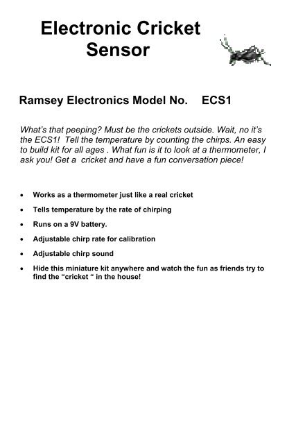
Electronic Cricket Sensor Ramsey Electronics ... - Tequipment.net
Electronic Cricket Sensor Ramsey Electronics ... - Tequipment.net
Electronic Cricket Sensor Ramsey Electronics ... - Tequipment.net

You also want an ePaper? Increase the reach of your titles
YUMPU automatically turns print PDFs into web optimized ePapers that Google loves.
<strong>Electronic</strong> <strong>Cricket</strong><br />
<strong>Sensor</strong><br />
<strong>Ramsey</strong> <strong>Electronic</strong>s Model No. ECS1<br />
What’s that peeping? Must be the crickets outside. Wait, no it’s<br />
the ECS1! Tell the temperature by counting the chirps. An easy<br />
to build kit for all ages . What fun is it to look at a thermometer, I<br />
ask you! Get a cricket and have a fun conversation piece!<br />
• Works as a thermometer just like a real cricket<br />
• Tells temperature by the rate of chirping<br />
• Runs on a 9V battery.<br />
• Adjustable chirp rate for calibration<br />
• Adjustable chirp sound<br />
• Hide this miniature kit anywhere and watch the fun as friends try to<br />
find the “cricket “ in the house!<br />
ECS1• 1
PARTIAL LIST OF AVAILABLE KITS:<br />
RAMSEY TRANSMITTER KITS<br />
• FM10A, FM25B FM Stereo Transmitters<br />
• AM1, AM25 Transmitter<br />
• PPM3 Phone Patch Mixer<br />
RAMSEY RECEIVER KITS<br />
• FR1 FM Broadcast Receiver<br />
• AR1 Aircraft Band Receiver<br />
• SR2 Shortwave Receiver<br />
• AA7 Active Antenna<br />
• SC1 Shortwave Converter<br />
RAMSEY HOBBY KITS<br />
• SG7 Personal Speed Radar<br />
• SS70A Speech Scrambler/Descrambler<br />
• TT1 Telephone Recorder<br />
• WEB1 Walking <strong>Electronic</strong> Bug<br />
• UAM2 20W Audio Amplifier<br />
• PG13 Plasma Generator<br />
• MD3 Microwave Motion Detector<br />
• TFM3 Tri-Field Meter<br />
RAMSEY AMATEUR RADIO KITS<br />
• HR Series HF All Mode Receivers<br />
• DDF1 Doppler Direction Finder Kit<br />
• QRP Series HF CW Transmitters<br />
• CW7 CW Keyer<br />
• QRP Power Amplifiers<br />
RAMSEY MINI-KITS<br />
Many other kits are available for hobby, school, scouts and just plain FUN. New<br />
kits are always under development. Write or call for our free <strong>Ramsey</strong> catalog.<br />
ECS1 <strong>Electronic</strong> <strong>Cricket</strong> <strong>Sensor</strong><br />
<strong>Ramsey</strong> <strong>Electronic</strong>s publication No. ECS1 Rev. 1.1<br />
January 2004<br />
COPYRIGHT © 2003 by <strong>Ramsey</strong> <strong>Electronic</strong>s, Inc. 590 Fishers Station Drive, Victor, New York<br />
14564. All rights reserved. No portion of this publication may be copied or duplicated without the<br />
written permission of <strong>Ramsey</strong> <strong>Electronic</strong>s, Inc. Printed in the United States of America.<br />
ECS1• 2
<strong>Electronic</strong> <strong>Cricket</strong><br />
<strong>Sensor</strong><br />
TABLE OF CONTENTS<br />
ECS1• 3<br />
<strong>Ramsey</strong> Publication No. ECS1<br />
Manual Price Only $5.00<br />
KIT ASSEMBLY<br />
AND INSTRUCTION MANUAL FOR<br />
Introduction to the ECS1 ................................... 4<br />
ECS1 Circuit Description................................... 4<br />
“Learn-As-You-Build” Kit Assembly....................6<br />
Parts List.............................................................7<br />
Assembly Steps..................................................8<br />
ECS1 Parts Layout Diagram ............................10<br />
ECS1 Schematic ..............................................11<br />
Setup and Testing ...........................................12<br />
Troubleshooting Guide .....................................12<br />
<strong>Ramsey</strong> Kit Warranty........................................15<br />
RAMSEY ELECTRONICS, INC.<br />
590 Fishers Station Drive<br />
Victor, New York 14564<br />
Phone (585) 924-4560<br />
Fax (585) 924-4555<br />
www.ramseykits.com
INTRODUCTION<br />
Everyone has heard the crickets outside their window peep, peep, peeping,<br />
but some people don’t know that those chirps can be used to measure<br />
temperature! If you count the number of chirps in 15 seconds and add 40,<br />
you have roughly the Fahrenheit temperature. Isn’t that swell? The ECS1 is<br />
an electronic version of those little temperature telling crickets. It will chirp to<br />
temperature just like them. So all you do is build it, tweak it, then: peep, peep<br />
peep, “Hey it’s 72 degrees out”.<br />
ECS1 CIRCUIT DESCRIPTION<br />
Well for all of you who haven’t seen enough of the uber-classsic LM555 timer<br />
IC, this circuit is for you. If by some chance there is someone who has not<br />
used one before, this kit will indoctrinate you into the “in” crowd and you will<br />
now be cool. There be three timers: U1, U2, and U3. They have teamed up<br />
to create the sound of the cricket. Before you understand the electronics you<br />
must understand the cricket chirp. I, the kit designer, have spent much time<br />
learning about this so that my kit will sound right. So, now you, the kit builder,<br />
shall be enlightened. A cricket chirp is composed of a group of three<br />
amplitude modulated sine waves occurring in rapid succession. Observe the<br />
picture. Each group of three is one chirp. This picture is an actual output from<br />
a wave file of recorded cricket sound. When it is played the result is: “chirp<br />
chirp chirp”. If you zoom way in on one chirp it looks like the next picture.<br />
As you can see, it is made up of a sine wave of a single frequency (about<br />
5KHz) that ramps up and then back down again. This is the essence of the<br />
cricket chirp. The ECS1 is meant to reproduce this closely enough that it<br />
ECS1• 4
sounds like a cricket chirp. The circuit responds to temperature by way of a<br />
thermistor, a resistor whose value changes with temperature. The thermistor<br />
is used as a timing resistor in U1. When the temperature changes, U1’s<br />
output frequency changes and so does the cricket chirp rate. In order to keep<br />
the circuit simple and inexpensive, some compromises had to be made. The<br />
main one is that the circuit is composed of elements that produce square<br />
waves, not sine waves. For audio guys, this may cause foaming at the<br />
mouth, but you can get some square waves to sound almost the same as a<br />
sine wave if you tweak everything right. To try to match the cricket chirp<br />
waveforms as closely as possible, three 555 timers are used. They are<br />
chained together in such a way that they modulate each other. The output of<br />
the first modulates the second, and the output of the second modulates the<br />
U1 Out<br />
U2 Out<br />
U3 Out<br />
third. Look upon the picture above. Keep in mind that this diagram just shows<br />
the “relative” frequencies generated by the three timers so you can see how<br />
the different waveforms look. In reality the output of U3 is much higher<br />
frequency, but if drawn that way would be too hard to see on this picture. As<br />
you can see the pulses from each 555 build up the final waveform. You will<br />
notice that the final waveform from U3 has groups of 4 pulses not three. This<br />
goes back to what was said about tweaking a circuit that produces square<br />
waves so that it sounds like the original sine wave pattern. By listening to the<br />
sound the circuit made as I adjusted the timings of the 555 timers, I found<br />
that these timings worked best. The circuit has a pot that will let you change<br />
the frequency of U3 so you can tweak the pitch of the cricket sound to your<br />
liking. The last stage in the circuit is an output transistor that drives the<br />
speaker.<br />
ECS1• 5
RAMSEY Learn-As-You-Build KIT ASSEMBLY<br />
There aren’t that many solder connections on the ECS1 printed circuit board,<br />
but you should still practice good soldering techniques.<br />
• Use a 25-watt soldering pencil with a clean, sharp tip.<br />
• Use only rosin-core solder intended for electronics use.<br />
• Use bright lighting; a magnifying lamp or bench-style magnifier may<br />
be helpful.<br />
• Do your work in stages, taking breaks to check your work. Carefully<br />
brush away wire cuttings so they don't lodge between solder<br />
connections.<br />
We have a two-fold "strategy" for the order of the following kit assembly steps.<br />
First, we install parts in physical relationship to each other, so there's minimal<br />
chance of inserting wires into wrong holes. Second, whenever possible, we<br />
install in an order that fits our "Learn-As-You Build" Kit building philosophy.<br />
This entails describing the circuit that you are building instead of just blindly<br />
installing components. We hope that this will not only make assembly of our<br />
kits easier, but help you to understand the circuit you’re constructing.<br />
For each part, our word "Install" always means these steps:<br />
1. Pick the correct part value to start with.<br />
2. Insert it into the correct PC board location.<br />
3. Orient it correctly, follow the PC board drawing and the written<br />
directions for all parts - especially when there's a right way<br />
and a wrong way to solder it in. (Diode bands, electrolytic<br />
capacitor polarity, transistor shapes, dotted or notched ends<br />
of IC's, and so forth.)<br />
4. Solder all connections unless directed otherwise. Use enough heat<br />
and solder flow for clean, shiny, completed connections.<br />
ECS1• 6
ECS1 PARTS LIST<br />
Sort and “check off” the components in the boxes provided. We do our best to<br />
pack all our kits correctly but it is possible that a mistake has occurred and we<br />
missed a part. Please note that physical descriptions of parts are for those<br />
currently being shipped. Sometimes the parts in your kit may have a different<br />
appearance but still have the same values.<br />
RESISTORS<br />
� 1 100 ohm resistor [brown-black-brown] (R10)<br />
� 1 470 ohm resistor [yellow-violet-brown] (R6)<br />
� 2 1K ohm resistor [brown-black-red] (R5,R8)<br />
� 1 10K ohm resistor [brown-black-orange] (R1)<br />
� 1 100K ohm resistor [brown-black-yellow] (R4)<br />
� 1 1K ohm potentiometer [orange top marked 102] (R9)<br />
� 1 5K ohm potentiometer [orange top marked 502] (R7)<br />
� 1 500K ohm potentiometer [orange top marked 504] (R2)<br />
� 1 100k thermistor (R3)<br />
CAPACITORS<br />
� 3 .01 uF ceramic disk capacitor [marked 103] (C7,C9,C10)<br />
� 5 .1 uF ceramic disk capacitor [marked 104] (C3,C4,C5,C6,C8)<br />
� 1 100 uF electrolytic capacitor (C2)<br />
� 1 2.2uF electrolytic capacitor (C1)<br />
SEMICONDUCTORS<br />
� 3 555 Timer IC [marked NE555N] (U1,U2,U3)<br />
� 4 1N4148 diode (D1,D2,D3,D4)<br />
� 1 78L05 voltage regulator (VR1)<br />
� 1 BS170 FET (Q1)<br />
MISCELLANEOUS<br />
� 1 red/black twisted wire, 4 inches<br />
� 1 DPDT switch<br />
� 1 8 ohm speaker<br />
� 1 9V battery connector<br />
ECS1• 7
ECS1 PC BOARD ASSEMBLY STEPS<br />
� 1. Take a look at the layout diagram. Let’s start with the bottom left of the<br />
board and install power switch S1. Be sure to use enough solder to firmly<br />
attach it to the board.<br />
� 2. Next, install D2, 1N4148 diode, to the right at the bottom of the board.<br />
Be sure it goes in the right way. Line up the black band on the part with<br />
the white band on the board drawing.<br />
� 3. Install R2, 500K potentiometer [marked 504], to the right of D2.<br />
� 4. Install R3, 100K thermistor, next to R2. This is the temperature sensor<br />
for your kit. At this point you can solder in the part directly to the board, or<br />
solder it to the end of a wire, and then solder the wire into the board. Using<br />
the wire method, you can place the thermistor a distance away from<br />
the board to measure temperature remotely. You can use the included<br />
wire, or your own wire, if you want it to be longer. If you decide to solder<br />
the thermistor onto the end of a wire, wrap some tape around the leads<br />
just to keep them from bending and possibly breaking off.<br />
� 5. Install D1, 1N4148 diode, above D2. Watch the polarity again.<br />
� 6. Install R1, 10K ohm resistor [brown-black-orange], above R2.<br />
� 7. Install C1, 2.2 uF electrolytic capacitor, above D1. Watch the polarity on<br />
this part too. Make sure the “-” lead goes in the “-” hole, and the “+” lead<br />
goes in the plus hole. There is a band on your cap marking “-” and a “+”<br />
symbol on the board.<br />
� 8. Install U1, the first of a trio of 555 timers. Make sure the notch on the<br />
chip lines up with the notch on the board drawing.<br />
� 9. Install Q1, BS170 “power” transistor. Power is in quotes because of a<br />
running argument between myself and another engineer here about MOS-<br />
FETS. For a tad more $$, I could have put a part in this kit that could start<br />
your car, but I SUPPOSE it isn’t necessary for driving a small speaker. I<br />
digress. Make sure Q1 goes in the right way. Line up the flat spot with the<br />
flat spot on the board drawing.<br />
� 10. Install R9, 1K ohm potentiometer [marked 102], to the right of Q1.<br />
� 11. Install C10, .01 uF ceramic disc capacitor [marked 103], above R9.<br />
� 12. Install C9, .01 uF ceramic disc capacitor [marked 103], above C10.<br />
� 13. Install C7, .01 uF ceramic disc capacitor [marked 103], above C10.<br />
� 14. Install C5, .1 uF ceramic disc capacitor [marked 104], above C9.<br />
ECS1• 8
� 15. Install D4, 1N4148 silicon diode, above C5. Watch the polarity.<br />
� 16. Install R5, 1K ohm resistor [brown-black-red], above D4.<br />
� 17. Install D3, 1N4148 diode, right next to R5. Once again, don’t put it in<br />
backwards just to be a rebel.<br />
� 18. Install R4, 100K resistor [brown-black-yellow], next to D3.<br />
� 19. Install R6, 470 ohm resistor [yellow-violet-brown], next to R4.<br />
� 20. Install U2, 555 timer IC under R4. Line up the notch like you did with<br />
U1.<br />
� 21. Install C3, .1 uF ceramic disc capacitor [marked 104], just to the left of<br />
U2.<br />
� 22. Install R10, 100 ohm resistor [brown-black-brown], to the left of C3.<br />
� 23. Install C2, 100 uF electrolytic capacitor, below C3. Follow the silkscreen<br />
for polarity!<br />
� 24. Install R8, 1K ohm resistor [brown-black-red], below C2.<br />
� 25. Install C4, .1 uF ceramic disc capacitor [marked 104], to the left of C2.<br />
� 26. Install R7, 5K ohm potentiometer [orange top marked 502], to the left<br />
of R10.<br />
� 27. Install C8, .1 uF ceramic disc capacitor [marked 104], above R7.<br />
� 28. Install U3, the last of the 555 timers, under R7. Line up the notch<br />
again.<br />
� 29. Install C6, .1 uF ceramic disc capacitor [marked 104], next to C6.<br />
� 30. Install VR1, 5V low power voltage regulator, next to C6. Line up the<br />
flat side with the flat spot on the board drawing.<br />
� 31. Solder in the 9V battery connector into pads P1 and P2. The black<br />
wire goes into P2 and the red one goes into P1.<br />
� 32. Solder in the speaker to pads P3 and P4 using the included wire or<br />
your own. It doesn’t matter what wire goes into which pad.<br />
Okay, enough of all of this stuff. Time to test it out!<br />
ECS1• 9
ECS1 BOARD PARTS LAYOUT DIAGRAM<br />
ECS1• 10
ECS1 MAIN BOARD SCHEMATIC<br />
ECS1• 11
SETUP AND TESTING<br />
Plug a 9V battery into the connector. You should hear some chirps coming out<br />
of the speaker. Turn R9 to adjust volume. Now turn R7 slowly to get the pitch<br />
that you think sounds most like a cricket. In addition you can remove one or<br />
both capacitors C9 and C10. This will change the sound more, but will also<br />
reduce volume. When you get the sound the way you like it, you need to calibrate<br />
the ECS1 so that it will chirp to the right frequency. The cricket-chirp-totemperature<br />
rule is: Count the number of chirps in 15 seconds and add 40.<br />
This gives the temperature in degrees Fahrenheit. Well, it gives the approximate<br />
temperature. No one is claiming that a cricket can replace a Fluke<br />
temperature probe. However, the cricket chirping does increase very linearly<br />
with frequency and is plenty accurate enough for an interesting fireside conversation<br />
starter. Anyway, when properly adjusted the ECS1 will duplicate the<br />
accuracy of a cricket over a typical cricket’s chirping temperature range of<br />
about 55°F to 90°F or more. To calibrate your ECS1 you need to turn it on and<br />
set R2 such that the chirp frequency is 2.13Hz, or 128 chirps per minute at 72°<br />
F. If you have an oscilloscope you can measure the frequency of pin 3 on U1<br />
and adjust R2 until it is exactly 2.13Hz. If you don’t, you can use the counting<br />
method; it will just take a little longer. To do this, count the number of chirps in<br />
a minute. Now divide by 4 and add 40. This is the temperature in °F. If this<br />
value is woefully wrong then you must adjust R2. If your ECS1 gives you a<br />
temperature that is too low, adujust R2 clockwise. If it gives you a temperature<br />
that is too high, adjust R2 counter-clockwise. You should start by measuring<br />
the resistance across R2 and turning it until the value is about 30.2K ohms, or<br />
about 2/3 of a turn counter-clockwise. When you get your cricket calibrated,<br />
put it somewhere interesting and listen to it peep peep until it drives your<br />
friends and family mad.<br />
TROUBLESHOOTING GUIDE<br />
This is a pretty easy kit to troubleshoot. Most problems can be found using a<br />
clear head and a logical approach. Make sure U1, U2, and U3 are in the right<br />
way. Then check Q1, D1, D2, D3, D4 for proper orientation. Check all parts for<br />
correct value and placement, and look over your solder joints to be sure that<br />
there are no cold solder joints, no solder bridges, and no open connections.<br />
Check for clipped off lead ends that may have lodged between the connections<br />
causing a short. Have a friend look over your work; sometimes another<br />
pair of eyes will catch mistakes that we miss. Make sure your regulator is putting<br />
out +5VDC and that you have that voltage on each of the 555 IC s at pin<br />
8. If all else fails check the warranty instructions on the inside back cover of<br />
this manual for details on sending the kit in for repair.<br />
ECS1• 12
CONCLUSION<br />
We sincerely hope that you will enjoy the use of this <strong>Ramsey</strong> product. As always,<br />
we have tried to compose our manual in the easiest, most “user<br />
friendly” format that is possible. As our customers, we value your opinions,<br />
comments, and additions that you would like to see in future publications.<br />
Please submit comments or ideas to:<br />
<strong>Ramsey</strong> <strong>Electronic</strong>s Inc.<br />
Attn. Hobby Kit Department<br />
590 Fishers Station Drive<br />
Victor, NY 14564<br />
or email us at: techsupport@ramseymail.com<br />
And once again, thanks from the folks at <strong>Ramsey</strong>!<br />
ECS1• 13
ECS1• 14
The <strong>Ramsey</strong> Kit Warranty<br />
Please read carefully BEFORE calling or writing in about your kit. Most<br />
problems can be solved without contacting the factory.<br />
Notice that this is not a "fine print" warranty. We want you to understand your rights and ours too! All<br />
<strong>Ramsey</strong> kits will work if assembled properly. The very fact that your kit includes this new manual is<br />
your assurance that a team of knowledgeable people have field-tested several "copies" of this kit<br />
straight from the <strong>Ramsey</strong> Inventory. If you need help, please read through your manual carefully, all<br />
information required to properly build and test your kit is contained within the pages! However,<br />
customer satisfaction is our goal, so in the event that you do have a problem, take note of the<br />
following.<br />
1. DEFECTIVE PARTS: It's always easy to blame a part for a problem in your kit, Before you conclude<br />
that a part may be bad, thoroughly check your work. Today's semiconductors and passive components<br />
have reached incredibly high reliability levels, and its sad to say that our human construction skills<br />
have not! But on rare occasions a sour component can slip through. All our kit parts carry the <strong>Ramsey</strong><br />
<strong>Electronic</strong>s Warranty that they are free from defects for a full ni<strong>net</strong>y (90) days from the date of<br />
purchase. Defective parts will be replaced promptly at our expense. If you suspect any part to be<br />
defective, please mail it to our factory for testing and replacement. Please send only the defective part<br />
(s), not the entire kit. The part(s) MUST be returned to us in suitable condition for testing. Please be<br />
aware that testing can usually determine if the part was truly defective or damaged by assembly or<br />
usage. Don't be afraid of telling us that you 'blew-it', we're all human and in most cases, replacement<br />
parts are very reasonably priced.<br />
2. MISSING PARTS: Before assuming a part value is incorrect, check the parts listing carefully to see<br />
if it is a critical value such as a specific coil or IC, or whether a RANGE of values is suitable (such as<br />
"100 to 500 uF"). Often times, common sense will solve a mysterious missing part problem. If you're<br />
missing five 10K ohm resistors and received five extra 1K resistors, you can pretty much be assured<br />
that the '1K ohm' resistors are actually the 'missing' 10 K parts ("Hum-m-m, I guess the 'red' band<br />
really does look orange!") <strong>Ramsey</strong> <strong>Electronic</strong>s project kits are packed with pride in the USA. If you<br />
believe we packed an incorrect part or omitted a part clearly indicated in your assembly manual as<br />
supplied with the basic kit by <strong>Ramsey</strong>, please write or call us with information on the part you need<br />
and proof of kit purchase.<br />
3. FACTORY REPAIR OF ASSEMBLED KITS:<br />
To qualify for <strong>Ramsey</strong> <strong>Electronic</strong>s factory repair, kits MUST:<br />
1. NOT be assembled with acid core solder or flux.<br />
2. NOT be modified in any manner.<br />
3. BE returned in fully-assembled form, not partially assembled.<br />
4. BE accompanied by the proper repair fee. No repair will be undertaken until we have received the<br />
MINIMUM repair fee (1/2 hour labor) of $25.00, or authorization to charge it to your credit card<br />
account.<br />
5. INCLUDE a description of the problem and legible return address. DO NOT send a separate letter;<br />
include all correspondence with the unit. Please do not include your own hardware such as non-<br />
<strong>Ramsey</strong> cabi<strong>net</strong>s, knobs, cables, external battery packs and the like. <strong>Ramsey</strong> <strong>Electronic</strong>s, Inc.,<br />
reserves the right to refuse repair on ANY item in which we find excessive problems or damage due to<br />
construction methods. To assist customers in such situations, <strong>Ramsey</strong> <strong>Electronic</strong>s, Inc., reserves the<br />
right to solve their needs on a case-by-case basis.<br />
The repair is $50.00 per hour, regardless of the cost of the kit. Please understand that our technicians<br />
are not volunteers and that set-up, testing, diagnosis, repair and repacking and paperwork can take<br />
nearly an hour of paid employee time on even a simple kit. Of course, if we find that a part was<br />
defective in manufacture, there will be no charge to repair your kit (But please realize that our<br />
technicians know the difference between a defective part and parts burned out or damaged through<br />
improper use or assembly).<br />
4. REFUNDS: You are given ten (10) days to examine our products. If you are not satisfied, you may<br />
return your unassembled kit with all the parts and instructions and proof of purchase to the factory for<br />
a full refund. The return package should be packed securely. Insurance is recommended. Please do<br />
not cause needless delays, read all information carefully.<br />
ECS1• 15
REQUIRED TOOLS<br />
• Soldering Iron (WLC100)<br />
• Thin Rosin Core Solder (RTS12)<br />
• Needle Nose Pliers (MPP4 or RTS05)<br />
• Small Diagonal Cutters (RTS04)<br />
ADDITIONAL SUGGESTED ITEMS<br />
• Helping Hands Holder for PC Board/Parts<br />
(HH3)<br />
• Technician’s Tool Kit (TK405)<br />
• Desoldering Braid (RTS08)<br />
Manual Price Only: $5.00<br />
<strong>Ramsey</strong> Publication No. ECS1<br />
Assembly and Instruction manual for:<br />
RAMSEY MODEL NO. ECS1 <strong>Electronic</strong><br />
<strong>Cricket</strong> <strong>Sensor</strong>.<br />
RAMSEY ELECTRONICS, INC.<br />
590 Fishers Station Drive<br />
Victor, New York 14564<br />
Phone (585) 924-4560<br />
Fax (585) 924-4555<br />
www.ramseykits.com<br />
ECS1 Quick Reference Page Guide<br />
ECS1 Circuit Description................................... 4<br />
Parts List............................................................. 7<br />
ECS1 Parts Layout Diagram ............................ 10<br />
ECS1 Schematic .............................................. 11<br />
Setup and Testing ........................................... 12<br />
<strong>Ramsey</strong> Kit Warranty ....................................... 15<br />
ECS1• 16<br />
TOTAL SOLDER POINTS<br />
95<br />
ESTIMATED ASSEMBLY<br />
TIME<br />
Beginner...............1.5 hrs<br />
Intermediate .........1 hrs<br />
Advanced ..............30 min