
Create successful ePaper yourself
Turn your PDF publications into a flip-book with our unique Google optimized e-Paper software.
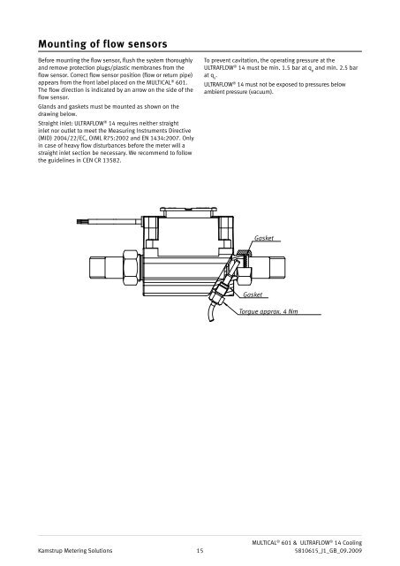
Mounting of flow sensorsBefore mounting the flow sensor, flush the system thoroughlyand remove protection plugs/plastic membranes from theflow sensor. Correct flow sensor position (flow or return pipe)appears from the front label placed on the MULTICAL ® 601.The flow direction is indicated by an arrow on the side of theflow sensor.Glands and gaskets must be mounted as shown on thedrawing below.Straight inlet: ULTRAFLOW ® <strong>14</strong> requires neither straightinlet nor outlet to meet the Measuring Instruments Directive(MID) 2004/22/EC, OIML R75:2002 and EN <strong>14</strong>34:2007. Onlyin case of heavy flow disturbances before the meter will astraight inlet section be necessary. We recommend to followthe guidelines in CEN CR 13582.To prevent cavitation, the operating pressure at theULTRAFLOW ® <strong>14</strong> must be min. 1.5 bar at q pand min. 2.5 barat q s.ULTRAFLOW ® <strong>14</strong> must not be exposed to pressures belowambient pressure (vacuum).GasketGasketTorgue approx. 4 NmKamstrup <strong>Metering</strong> Solutions15MULTICAL ® 601 & ULTRAFLOW ® <strong>14</strong> Cooling5810615_J1_GB_09.2009