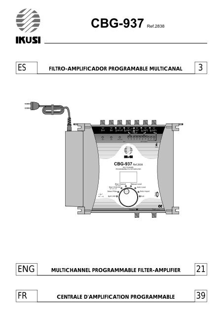
Manual IK-CBG-937 - Vaag.es
Manual IK-CBG-937 - Vaag.es
Manual IK-CBG-937 - Vaag.es
- No tags were found...

Create successful ePaper yourself
Turn your PDF publications into a flip-book with our unique Google optimized e-Paper software.
BI-II+15V INBIIISAT SlopeSAT ON / OFF022 kHz18V24V 24V 13V24V 24V0VVHF-UHFSAT+1 2 3 4 5 6 7 8 9 10UHF ClustersMULTICHANNELPROGRAMMABLE FILTER-AMPLIFIERGNDINSTRUCCIONES DE SEGURIDADLeer con cuidado <strong>es</strong>tas instruccion<strong>es</strong> ant<strong>es</strong> de conectar la unidad.El voltaje viene indicado en el adaptador.Para prevenir fuego, corto-circuito, peligro de d<strong>es</strong>cargas:No exponga la unidad a la lluvia o humedad.Instale la unidad en un lugar seco sin filtracion<strong>es</strong> o condensacion<strong>es</strong> de agua.No la exponga a salpicaduras.No ponga objetos con líquido, en el aparato.Si cae algún líquido en la carcasa accidentalmente, d<strong>es</strong>conecte la corriente.Diríjase a un tecnico cualificado ant<strong>es</strong> de su pu<strong>es</strong>ta en marcha.Para evitar ri<strong>es</strong>gos por calentamiento:Instale la unidad en un buen lugar y mantenga una distancia mínima de 15 cm alrededor del aparatocon suficiente ventilación.No ponga ningún articulo como papel de periódico, mantel<strong>es</strong>, cortinas... encima de la unidad quepuedan cubrir las aperturas de ventilación.La unidad no debe ser expu<strong>es</strong>ta a fuent<strong>es</strong> de calor (sol, calefacción,...).No ponga ninguna fuente de calor, tal<strong>es</strong> como velas en el aparato.No instale el aparato en un lugar con mucho polvo.D<strong>es</strong>conecte el cable de corriente para realizar las diferent<strong>es</strong> conexion<strong>es</strong>.Para evitar d<strong>es</strong>cargas eléctricas, no abra la carcasa del adaptador.Limpieza :Use solamento un paño seco para limpiar la carcasa. No utilice disolvent<strong>es</strong>.Mantenimiento :Para reparacion<strong>es</strong> o mantenimiento diríjase a personal cualificado.MONTAJE(4)212.5 mm.(5)(2)(3)BI-II BIII VHF-UHF UHF1 18V SAT UHF2 UHF324V 24V 13V24V 24V0VBI-IIBIII VHF-UHF1 2 3 4 5 6 7 8 9 10SATUHF ClustersGND<strong>CBG</strong>-<strong>937</strong> Ref.2838MULTICHANNELPROGRAMMABLE FILTER-AMPLIFIER022 kHz(1)185 mm.(1) Tierra(2) Ponga el adaptador en su soporte(3) Conecte la fuente de alimentaciónal amplificador(4) Conecte el cable de redal adaptador(5) Inserte el soporte del adaptadora la carcasa del amplificadorStop ChannelSAT SlopeStart ChannelSAT ON / OFF<strong>Manual</strong> LevelAuto LevelSelect FilterData Import15VINSplit UHFExitDataOutputT<strong>es</strong>t (-30 dB)(5)15 cm.15 cm.BI-II BIII VHF-UHF UHF1SAT<strong>CBG</strong>-<strong>937</strong> Ref.2838UHF2UHF315 cm.ParedVentilación15 cm.IMPORTANTE :Este amplificador <strong>es</strong>tá equipadocon un ventilador en la parte posteriorpara mejorar la capacidad deventilación.Deje un <strong>es</strong>pacio mínimo de 15 cmalrededor del producto paragarantizar la maxima ventilación.Start ChannelStop Channel<strong>Manual</strong> LevelAuto LevelSelect FilterData ImportSplit UHFExitDataOutputT<strong>es</strong>t (-30 dB)15 cm.Ventilación4
OPERACIONESTodos los parámetros son fijados con el botón de pr<strong>es</strong>ión rotativo.Cada función y parámetros se mu<strong>es</strong>tran mediante un display de 2 dígitos y diferent<strong>es</strong> LEDs.Programación- Realice todas las conexion<strong>es</strong> nec<strong>es</strong>arias y conecte el amplificador a la corriente.- Pr<strong>es</strong>ione el botón durante más de 3 segundos para acceder al sistema de programación.3sec.La versión del software saleen el display.seguido de un punto.Entrada modo de programación- Gire el botón para seleccionar el modo d<strong>es</strong>eado.El modo <strong>es</strong>tá indicadocon un LED de colorverde.= LED verde= LED rojo- Pr<strong>es</strong>ione el botón para entrar al modo seleccionado.El LED <strong>es</strong> ahora rojo.- Dentro del modo, gire el botón para seleccionar el parámetro (entrada, cluster, canal, nivel, …)I-II III VHF-UHF1 2 3 4 5 6 7 8 9 10UHF clustersLEDs Entradas y ClustersDisplay- Pr<strong>es</strong>ione el botón para confirmar la programación.LED vuelve a ponerse verde.Repita <strong>es</strong>ta sección para ajustar todos los parámetros- Gire el botón para seleccionar el modo Exit (Salir).- Pr<strong>es</strong>ione el botón para confirmar.ExitEl LED <strong>es</strong>tá verde.Un punto aparece en el display.Salida modo programaciónNota :El amplificador pasará a modo "stand-by" y aparecerá un punto en el display pasado un minuto sin usar el botón.6
PROGRAMACION CLUSTERSAjustar clusters / Entradas UHF- El amplificador tiene 3 entradas UHF las cual<strong>es</strong> <strong>es</strong>tán divididas sobre 10 clusters.Hay Tr<strong>es</strong> posibl<strong>es</strong> configuracion<strong>es</strong> :EntradaNúmero decluster(s)UHF1222UHF2875UHF3013UHF1 los clusters <strong>es</strong>tán indicados por LEDs AMARILLOS n° 1 y 2UHF2 los clusters <strong>es</strong>tán indicados por LEDs ROJOS n° 3,4,5,6,7,8,9 y 10UHF3 clusters <strong>es</strong>tán indicados por LEDs VERDES n° 8,9 y 10Para ajustar el número de clusters por entrada :- Gire el botón para seleccionar el modo Split UHF (Entrada UHF).Split UHFEl LED <strong>es</strong>tá verde.- Pr<strong>es</strong>ione el botón para confirmar.Split UHFEl LED <strong>es</strong>tá rojo.- Gire el botón para ajustar una configuración :I-II III VHF-UHF1 2 3 4 5 6 7 8 9 10UHF clustersIndicador cluster UHF1Indicador cluster UHF2Indicador cluster UHF3- Pr<strong>es</strong>ione el botón para confirmar.Split UHFEl LED <strong>es</strong>tá verde.Notas :- UHF1 <strong>es</strong>ta ajustado para 2 clusters, UHF2 y UHF3 <strong>es</strong>tan configurados para diferent<strong>es</strong> numeros de clusters.- Cada cluster puede ser d<strong>es</strong>conectado (Función de Aparcado).Por ejemplo, si sólo nec<strong>es</strong>itas un cluster para UHF1, ajuste el segundo cluster en el canal 00 parad<strong>es</strong>conectarlo (vea el párrafo siguiente capítulo "Ajustando canal<strong>es</strong> / clusters").7
Ajustando canal<strong>es</strong> / clustersCada cluster tiene un ancho de banda el cual puede ser programado d<strong>es</strong>de 1 a 7 canal<strong>es</strong> :Para ajustar el canal o canal<strong>es</strong> por cluster :En el ejemplo siguiente el cluster 1 <strong>es</strong> ajustado para los canal<strong>es</strong> 22 a 26- Gire el botón para seleccionar el modo Select Filter (Selección Filtro).Select Filter- Pr<strong>es</strong>ione el botón para entrar en el modo seleccionado.Select FilterModo <strong>es</strong>tá indicadocon el LED de colorVERDE.El LED <strong>es</strong>tá ahora ROJO.= LED verde= LED rojo- Dentro del modo, gire el botón para seleccionar el cluster, que se va a ajustar.- Pr<strong>es</strong>ione el botón para confirmar.I-II III VHF-UHFLED n° 11 2 3 4 5 6 7 8 9 10UHF clustersSelect FilterEl LED <strong>es</strong>tá verde.- Gire el botón para seleccionar modo Start Channel (Canal Inicial).Start ChannelEl LED <strong>es</strong>tá verde.- Pr<strong>es</strong>ione el botón para entrar en el modo seleccionado.Start ChannelEl LED <strong>es</strong>tá ahora en ROJO.- Gire el botón para seleccionar el canal inicial.Display- Pr<strong>es</strong>ione el botón para confirmar.Start ChannelEl LED <strong>es</strong>tá verde.- Gire el botón para seleccionar el modo Stop Channel (Canal Final).Stop ChannelEl LED <strong>es</strong>tá verde.- Pr<strong>es</strong>ione el botón para entrar en el modo seleccionado.Stop ChannelEl LED <strong>es</strong>tá ahora ROJO.- Gire el botón para seleccionar el canal final.Display- Pr<strong>es</strong>ione el botón para confirmar.Stop ChannelEl LED <strong>es</strong>tá verde.Repita <strong>es</strong>ta sección para ajustar todos los clusters.8
Notas :- Modo MonocanalCuando el canal de comienzo <strong>es</strong> seleccionado, el canal finalización <strong>es</strong> ajustado automáticamente con elmismo valor.Start Channel- Función de aparcado :Para d<strong>es</strong>conectar el cluster, seleccione Start Channel (Canal Inicial) y ajuste canal 00.El Stop Channel (Canal Final) ira automáticamente al canal 00.Start Channel- Si hay clusters solapados, el display emite un punto parpadeante de forma intermitente.Start ChannelClusterc22c26Cluster 1 = c 22 a c 26Cluster 2 = c 25 a c 29c25c29canalCluster 29
Para comprobar los ajust<strong>es</strong> de canal por cada cluster.- Gire el botón para seleccionar el modo Select Filter (Selección Filtro).Select FilterEl LED <strong>es</strong>tá verde.- Pr<strong>es</strong>ione el botón para entrar en el modo seleccionado.Select FilterEl LED <strong>es</strong>tá ahora ROJO.- Gire el botón para seleccionar el cluster que d<strong>es</strong>ea comprabar.I-II III VHF-UHF1 2 3 4 5 6 7 8 9 10UHF clusters- El display mu<strong>es</strong>tra los canal<strong>es</strong> ajustados.Ejemplos :Cluster d<strong>es</strong>conectado.Cluster ajustado al canal 22.Cluster 22 y 26 alternativamente:cluster ajustado d<strong>es</strong>de el 22 al 26.- Pr<strong>es</strong>ione el botón para salir.Select FilterEl LED <strong>es</strong>tá verde.10
AJUSTE DE NIVELLos nivel<strong>es</strong> son ajustados manualmente por cada entrada y/o automáticamente para los clusters.Ajuste automático del nivel.Los nivel<strong>es</strong> de BI-II / BIII /VHF-UHF / SAT no se proc<strong>es</strong>an con la función de Nivel Automático.- Gire el botón para seleccionar el modo Auto Level (Nivel Automático).Auto LevelEl LED <strong>es</strong>tá en VERDE.- Pr<strong>es</strong>ione el botón durante más de 3 segundos para iniciar la función Auto Level.Auto LevelEl LED <strong>es</strong>tá ahora ROJO.3sec.El nivel se ajusta automáticamente por cada cluster.1 2 3 4 5 6 7 8 9 10UHF clustersEl LED activado indica el cluster que actualment<strong>es</strong>e <strong>es</strong>tá proc<strong>es</strong>ando.El display mu<strong>es</strong>tra el valor de la atenuación.Este proc<strong>es</strong>o durará aprox. 1 a 2 minutos, indicando a continuación los canal<strong>es</strong> y clustersque se <strong>es</strong>tán ecualizando.- Cuando el LED se ponga en VERDE, el procedimiento ha terminado.Auto LevelEl LED <strong>es</strong>tá VERDE- El LED de cada cluster mu<strong>es</strong>tra el <strong>es</strong>tado de la ecualización.1 2 3 4 5 6 7 8 9 10UHF clustersApagado: cluster d<strong>es</strong>conectadoEncendido: Nivel correctoParpadeo lento: Nivel bajoParpadeo rápido: Nivel demasiado fuerteNotas:- El ajuste automático fija el nivel de salida del cluster a 100 dBµV (para una señal de entrada entre 50 y 80 dBµV).Si el nivel de entrada <strong>es</strong> inferior a 50 dBµV, el LED parpadeará lentamente d<strong>es</strong>pués del procedimiento deajuste automático.Si el nivel de entrada <strong>es</strong> mayor a 80 dBµV, el LED parpadeará rápidamente.Reajustar el nivel de entrada (atenuación o ganancia) si fuera nec<strong>es</strong>ario.- El atenuador general se fija a 0 dB d<strong>es</strong>pués del ajuste automático.Se puede reajustar en un rango de -9 a +10 dB para obtener un nivel de salida entre 91 y 110 dBuV(ver "Ajuste general del nivel de UHF).- El nivel de cada cluster se puede ajustar de forma independiente (ver "Ajuste manual del nivel")IMPORTANTE: La indicación de los 10 LEDs no cambiará d<strong>es</strong>pués del ajuste manual de los clusters.11
Cuando el nivel de los clusters ha sido ecualizado individualmente, el nivel general de las señal de UHF(clusters y parte de la entrada VHF-UHF) pueden ser ajustados en pasos de 1 dB d<strong>es</strong>de +10 dB hasta -9 dB.Ajuste general del nivel de UHF.Para ajustar los nivel<strong>es</strong> general<strong>es</strong> de UHF.Seleccione todos los clusters y VHF-UHF.- Gire el botón para seleccionar el modo Select Filter (Selección Filtro).Select FilterEl LED <strong>es</strong>tá verde.- Pr<strong>es</strong>ione el botón para entrar en el modo seleccionado.Select FilterEl LED <strong>es</strong>tá ahora ROJO.- Gire el botón para seleccionar toda la UHF.I-II III VHF-UHF1 2 3 4 5 6 7 8 9 10UHF clustersTodos los LEDs <strong>es</strong>tán activados- Pr<strong>es</strong>ione el botón para confirmar.Select FilterEl LED <strong>es</strong>tá verde.- Gire el botón para seleccionar el modo <strong>Manual</strong> Level (Nivel <strong>Manual</strong>).<strong>Manual</strong> levelEl LED <strong>es</strong>tá verde.- Pr<strong>es</strong>ione el botón para entrar en el modo seleccionado.<strong>Manual</strong> LevelEl LED <strong>es</strong>tá ahora ROJO.- Gire el botón para ajustar el nivel general, variable d<strong>es</strong>de +10 dB hasta -9 dB.- Pr<strong>es</strong>ione el botón para confirmar.<strong>Manual</strong> LevelEl LED <strong>es</strong>tá verde.12
AJUSTE DE NIVELLos nivel<strong>es</strong> son ajustados manualmente por cada entrada y / o automáticamente para los clusters.Ajuste manual del nivel.Para ajustar manualmente el nivel.- Seleccione la entrada o cluster d<strong>es</strong>eado.Ejemplo : ajustar el nivel de BI-II.- Gire el botón para seleccionar el modo Select Filter (Selección Filtro).Select FilterEl LED <strong>es</strong>tá verde.- Pr<strong>es</strong>ione el botón para entrar en el modo seleccionado.Select FilterEl LED <strong>es</strong>tá ahora ROJO.- Gire el botón para seleccionar BI-II.I-II III VHF-UHFLED <strong>es</strong>tá activado1 2 3 4 5 6 7 8 9 10UHF clusters- Pr<strong>es</strong>ione el botón para confirmar.Select FilterEl LED <strong>es</strong>tá verde.- Gire el botón para seleccionar el modo <strong>Manual</strong> Level (Nivel <strong>Manual</strong>).<strong>Manual</strong> LevelEl LED <strong>es</strong>tá verde.- Pr<strong>es</strong>ione el botón para entrar el modo seleccionado.<strong>Manual</strong> LevelEl LED <strong>es</strong>tá ahora ROJO.- Gire el botón para ajustar el nivel manualmente, se puede variar d<strong>es</strong>de 20 dB hasta 0 dB(30 dB hasta 0 dB para clusters).- Pr<strong>es</strong>ione el botón para confirmar.<strong>Manual</strong> LevelEl LED <strong>es</strong>tá verde.Repita <strong>es</strong>ta sección para ajustar todos los nivel<strong>es</strong>13
Funcionamiento SATSelectionar la entrada SAT.- Gire el botón para seleccionar el modo Select Filter (Selección Filtro).Select FilterEl LED <strong>es</strong>tá verde- Pr<strong>es</strong>ione el botón para entrar en el modo seleccionado.Select FilterEl LED <strong>es</strong>tá ahora rojo- Gire el botón para seleccionar SAT.I-II III VHF-UHFSAT1 2 3 4 5 6 7 8 9 10UHF ClustersLED <strong>es</strong>tá actividoEl displaymu<strong>es</strong>tra el status "ON" o "OFF"- Pr<strong>es</strong>ione el botón para confirmar.Select FilterEl LED <strong>es</strong>tá verde.14
Para ajustar la ganancia.- Gire el botón para seleccionar el modo <strong>Manual</strong> Level (Nivel <strong>Manual</strong>).<strong>Manual</strong> LevelEl LED <strong>es</strong>tá verde- Pr<strong>es</strong>ione el botón para entrar en el modo seleccionado.<strong>Manual</strong> LevelEl LED <strong>es</strong>tá ahora rojo- Gire el botón para ajustar el nivel, variable d<strong>es</strong>de 20 dB hasta 0 dB.- Pr<strong>es</strong>ione el botón para confirmar.<strong>Manual</strong> LevelEl LED <strong>es</strong>tá verdePara ajustar la pendiente.- Gire el botón para seleccionar el modo SAT Slope (Pendiente SAT).SAT SlopeEl LED <strong>es</strong>tá verde- Pr<strong>es</strong>ione el botón para entrar en el modo seleccionado.SAT SlopeEl LED <strong>es</strong>tá ahora rojo- Gire el botón para ajustar la pendiente, variable d<strong>es</strong>de 0 dB hasta -9 dB.Pendiente- 0 dB- 9 dB- Pr<strong>es</strong>ione el botón para confirmar.SAT Slope950MHzFreq.2300MHzEl LED <strong>es</strong>tá verde15
Para d<strong>es</strong>activar el amplificador SAT- Gire el botón para seleccionar el modo Select Filter (Selección Filtro).Select FilterEl LED <strong>es</strong>tá verde- Pr<strong>es</strong>ione el botón para entrar en el modo seleccionado.Select FilterEl LED <strong>es</strong>tá ahora rojo- Gire el botón para seleccionar SAT.I-II III VHF-UHFSAT1 2 3 4 5 6 7 8 9 10UHF ClustersLED <strong>es</strong>tá activido- Pr<strong>es</strong>ione el botón para confirmar.Select FilterEl LED <strong>es</strong>tá verde- Gire el botón para seleccionar el modo SAT ON / OFF.SAT ON/OFFEl LED <strong>es</strong>tá verde- Pr<strong>es</strong>ione el botón para entrar en el modo seleccionado.SAT ON/OFFEl LED <strong>es</strong>tá ahora rojo- Gire el botón para d<strong>es</strong>activar el amplificador SAT.- Pr<strong>es</strong>ione el botón para confirmar.SAT ON/OFFEl LED <strong>es</strong>tá verde16
BI-II+15V INBIIIVHF-UHFSAT SlopeSAT ON / OFFSAT022 kHz18V24V 24V 13V24V 24V0V1 2 3 4 5 6 7 8 9 10UHF ClustersGNDBI-II+15V INBIIISAT SlopeSAT ON / OFFVHF-UHFSAT022 kHz18V24V 24V 13V24V 24V0V1 2 3 4 5 6 7 8 9 10UHF ClustersGNDFUNCION COPIAEsta función permite transmitir todos los ajust<strong>es</strong> d<strong>es</strong>de una unidad a otra unidad.Todas las accion<strong>es</strong> deben ser realizadas en la unidad ESCLAVA.La unidad MAESTRA permanece en Stand-by.BI-II BIII VHF-UHF UHF1SATUHF2UHF3BI-II BIII VHF-UHF UHF1SATUHF2UHF3<strong>CBG</strong>-<strong>937</strong> Ref.2838MULTICHANNELPROGRAMMABLE FILTER-AMPLIFIER<strong>CBG</strong>-<strong>937</strong> Ref.2838MULTICHANNELPROGRAMMABLE FILTER-AMPLIFIERStop ChannelStart Channel<strong>Manual</strong> LevelAuto LevelStart ChannelStop Channel<strong>Manual</strong> LevelAuto LevelSelect FilterData ImportSelect FilterData ImportSplit UHFExitDataSplit UHFExitDataOutputT<strong>es</strong>t (-30 dB)OutputT<strong>es</strong>t (-30 dB)EsclavaMa<strong>es</strong>tra- Conecte la unidad Ma<strong>es</strong>tra y la Esclava con un cable DSUB9 macho/macho cruzado.- D<strong>es</strong>pués conecte la corriente de las unidad<strong>es</strong>.DatosLa version del software aparece en el display,seguido de un punto.- Pr<strong>es</strong>ione el botón durante más de 3 segundos para entrar en el modo de programación.- Gire el botón para seleccionar el modo Data Import.3sec.Data ImportEl LED <strong>es</strong>tá verde.- Pr<strong>es</strong>ione el botón para entrar en el modo seleccionado.Data ImportEl LED <strong>es</strong>tá ahora ROJO.AL aparece en el display.- Pr<strong>es</strong>ione el botón para confirmar Data Import.La version del software aparece en el display,seguido de un punto.Nota :Si ocurre un problema durante la transmisión de datos el display mostrará un mensaje de error :Los posibl<strong>es</strong> causas son: el cable no <strong>es</strong> el adecuado, no hay cable, mal contacto en los pins...17
BI-II+15V INBI-II+15V INBIIISAT SlopeSAT ON / OFFBIIIVHF-UHFSAT022 kHz18V24V 24V 13V24V 24V0VMULTICHANNELPROGRAMMABLE FILTER-AMPLIFIERVHF-UHFSAT SlopeSAT ON / OFFSAT1 2 3 4 5 6 7 8 9 10UHF Clusters022 kHz18V24V 24V 13V24V 24V0V1 2 3 4 5 6 7 8 9 10MULTICHANNELPROGRAMMABLE FILTER-AMPLIFIERUHF ClustersGNDGNDRESET GENERALEsta función puede re<strong>es</strong>tablecer los clusters y los atenuador<strong>es</strong> al valor cero.- D<strong>es</strong>conecte el cable de red.BI-II BIII VHF-UHF UHF1SATUHF2UHF3<strong>CBG</strong>-<strong>937</strong> Ref.2838Start ChannelStop Channel<strong>Manual</strong> LevelAuto LevelSelect FilterData ImportSplit UHFExitDataOutputT<strong>es</strong>t (-30 dB)- Mantenga el botón pulsado.- Hasta que haya conectado de nuevo el cable de red.BI-II BIII VHF-UHF UHF1SATUHF2UHF3<strong>CBG</strong>-<strong>937</strong> Ref.2838Start ChannelStop Channel<strong>Manual</strong> LevelAuto LevelSelect FilterData ImportSplit UHFExitDataOutputT<strong>es</strong>t (-30 dB)La versión del software saleen el displayseguido de un punto.- Suelte ahora el botón.18
DIAGRAMA DE BLOQUESAt.20 dBBI-II BIII VHF-UHF UHF 1 UHF 2 UHF 3DC DC DC DC1 2 3 4 5 6 7 8 9 10At.30 dBUHFTAPVHFTAPAt. generalAtt. 20 dBAlta potenciaUHFVHF SATSalidaNivel autoT<strong>es</strong>t-30 dBSAT0/13/18 V0-22 kHzAt.20 dBPendiente9 dB19
ESPECIFICACIONES TECNICASEntradasRango de frecuencia (MHz)Configuraciónde losclustersGanancia (dB)Atenuador (dB)Ajuste de pendiente (dB)Nivel general ajustable UHF (dB)Figura de ruido (dB)Nivel máximo Entrada (dBµV)Nivel máximo Salida (dBµV)SelectividadPerdida de retornoEntrada / Salida (dB)Paso de corriente selectivoT<strong>es</strong>t de salida (dB)Transferencia datosAlimentaciónTemperatura de funcionamiento (C°)Dimension<strong>es</strong> (mm.)* TERR.: -54 dB / IM3 SAT: -35 dB / IM3BI-FM47-108BIII174-240VHF-UHF47-240 + 470-862UHF 1470-862UHF 2470-8628-56 (1 a 7 canal<strong>es</strong> / cluster)UHF 3470-862SAT950-2300-3520--4020--4020-222-8755530-013--40209- - - +10 dB a -9 dB-580118580118580VHF:118 / UHF:123680123990116- - - 10 dB / 10 MHzSAT / TERR. > 30 dBTERR. / SAT > 25 dB> 10 > 10 > 10 > 10 > 10 > 10>10- -24 V24 V24 V24 V 0-13-18 V / 300 mA100 mA en totaly 0-22 kHz-30Conector DSUB9230 V~ / 15 V DC / 45 VA-5 a +50265 x 220 x 95Todas las <strong>es</strong>pecificacion<strong>es</strong> pueden ser sujetos a cambios sin previo aviso.20
<strong>CBG</strong>-<strong>937</strong> Ref.2838MULTICHANNEL PROGRAMMABLE FILTER-AMPLIFIERInstallation instructionsBI-II BIII VHF-UHF UHF1022 kHzSATUHF218V24V 24V 13V24V 24V0VUHF3BI-IIBIIIVHF-UHF1 2 3 4 5 6 7 8 9 10SATUHF ClustersGND<strong>CBG</strong>-<strong>937</strong> Ref.2838MULTICHANNELPROGRAMMABLE FILTER-AMPLIFIERStop ChannelSAT SlopeStart ChannelSAT ON / OFF<strong>Manual</strong> LevelAuto LevelSelect FilterData Import15V+INSplit UHFExitDataOutputT<strong>es</strong>t (-30 dB)FEATURES- D<strong>es</strong>igned for both digital and analogue Satellite and Terr<strong>es</strong>trial channels,- 1 SAT input + 6 Terr<strong>es</strong>trial inputs :B I-II / B III / VHF-UHF and 3 UHF inputs splitted over 10 UHF programmable clusters,- Each cluster can have 1 to 7 channels bandwidth,- Easy programming by using one rotary / push button viewed on 2 digits display and LEDs for each clusterand each input,- 'COPY' function in order to transfer all settlements from one unit to another reducing time of installation,- High selectivity filters,- Low noise figure amplifiers,- High gain and output power,- VHF-UHF-SAT split band amplifiers with interstage attenuators for VHF-UHF,- Automatic leveling of signal or manual by attenuator with 1 dB step for accurate equalization- Selectable remote power on VHF-UHF and UHF inputs,- 0 - 13 - 18V / 0 - 22 kHz remote power for LNB,- -30 dB T<strong>es</strong>t output.21
BI-II+15V INBIIISAT SlopeSAT ON / OFFVHF-UHFSAT022 kHz18V24V 24V 13V24V 24V0V1 2 3 4 5 6 7 8 9 10UHF ClustersGNDSAFETY INSTRUCTIONSRead carefully th<strong>es</strong>e instructions before connecting the unit.The operating voltage is indicated on the adapter.To prevent fire, short circuit, shock hazard:Do not expose the unit to rain or moisture.Install the unit in a dry location without infiltration or condensation of water.Do not expose it to dripping or splashing.Do not place objects filled with liquids, such as vas<strong>es</strong>, on the apparatus.If any liquid should accidentally fall into the cabinet, disconnect the power plug.Refer to qualified technician before it's further operation.To avoid any risk of overheating:Install the unit in a well aery location and keep a minimum distance of 15 cm around the apparatus forsufficient ventilation.Do not place any items such as newspapers, table-cloths, curtains ... on the unit that might cover the ventilation hol<strong>es</strong>.The unit must not be exposed to any source of heat (sun, heater,...).Do not place any naked flame sourc<strong>es</strong>, such as lighted candl<strong>es</strong>, on the apparatus.Do not install the product in a dusty place.Pull out power plug to make the different connections of cabl<strong>es</strong>.To avoid electrical shock, do not open the housing of adapter.Cleaning :Only use a dry soft cloth to clean the cabinet. Do not use solvent.Servicing :For repairing and servicing refer to qualified personnel.Mounting(4)212.5 mm.(5)(2)(3)BI-II BIII VHF-UHF UHF1 18V SAT UHF2 UHF324V 24V 24V 24VBI-IIBIII VHF-UHF 1 2 3 4 5 6 7 8 9 10SATUHF ClustersGND<strong>CBG</strong>-<strong>937</strong> Ref.2838MULTICHANNELPROGRAMMABLE FILTER-AMPLIFIER022 kHz13V0V(1)185 mm.(1) Earthing(2) Place the adapter in its holder(3) Connect the power supplyto the amplifier(4) Plug the mains cable to the adapter(5) Click the adapter holder tothe amplifierStop ChannelSAT SlopeStart ChannelSAT ON / OFF<strong>Manual</strong> LevelAuto LevelSelect FilterData Import15V+INSplit UHFExitDataOutputT<strong>es</strong>t (-30 dB)(5)15 cm.15 cm.BI-II BIII VHF-UHF UHF1SAT<strong>CBG</strong>-<strong>937</strong> Ref.2838MULTICHANNELPROGRAMMABLE FILTER-AMPLIFIERUHF2UHF315 cm.WallVentilation IMPORTANT :this amplifier is equiped with a fanon the back side to improve coolingcapacity.Leave a minimum space of 15 cm.around the product to guarantee15 cm.a maximum ventilation.Start ChannelSelect FilterSplit UHFStop Channel<strong>Manual</strong> LevelAuto LevelData ImportExitDataOutputT<strong>es</strong>t (-30 dB)15 cm.Ventilation22
OPERATIONAll parameters are set with the rotary push button.Each function and parameters are shown on 2 digits display and different LEDs .Programming- Make all the nec<strong>es</strong>sary connections and connect amplifier to mains.The software version is displayed,followed by a dot.- Push on the rotary button for more than 3 seconds to enter into programming mode.Enter programming mode3sec.- Turn the button to select the d<strong>es</strong>ired mode.Mode is indicated witha GREEN colored LED.= green LED= red LED- Push the rotary button to enter the selected mode.The LED is now RED colored.- Inside the mode, turn the button to select the parameter (input, cluster, channels, level...)I-II III VHF-UHF1 2 3 4 5 6 7 8 9 10UHF ClustersInput and Cluster LEDsDisplay- Push the button to confirm the parameter setting.LED returns to a GREEN color.Repeat this section to set all parameters- Turn the button to select Exit mode.- Push the button to confirm.ExitThe LED is green.A dot is displayed.Exit programming modeNote :The amplifier will go in "stand-by" and will display a dot after 1 minute if the rotary / push button is not activated.24
CLUSTER PROGRAMMINGSetting clusters / UHF input- The amplifier has 3 UHF inputs which are splitted over 10 clusters.There are three possible configurations :InputNumber ofcluster(s)UHF1222UHF2875UHF3013UHF1 clusters are indicated by the YELLOW LEDs n° 1 and 2.UHF2 clusters are indicated by the RED LEDs n° 3, 4, 5, 6, 7, 8, 9 and 10.UHF3 clusters are indicated by the GREEN LEDs n° 8, 9 and 10.To set the number of cluster(s) per input :- Turn the button to select Split UHF mode.Split UHFThe LED is green.- Push the button to confirm.Split UHFThe LED is red.- Turn the button to set one configuration :I-II III VHF-UHF1 2 3 4 5 6 7 8 9 10UHF ClustersUHF1 cluster indicatorUHF2 cluster indicatorUHF3 cluster indicator- Push the button to confirm.Split UHFThe LED is green.Not<strong>es</strong> :- UHF1 is set for 2 clusters, UHF2 and UHF3 are set for different number of cluster(s).- Each cluster can be switched off (Park function).For example if you only need one cluster for UHF1, set the second cluster on channel 00 to switch it off(see following paragraph "Setting channels / cluster").25
Setting channels / clusterEach cluster has a bandwidth which can be programmed from 1 to 7 channels :To set the channel(s) per cluster :In the following example cluster 1 is set for channel 22 to channel 26.- Turn the button to select the Select Filter mode.Select Filter- Push the rotary button to enter the selected mode.Select FilterMode is indicated witha GREEN colored LED.The LED is now RED colored.= green LED= red LED- Inside the mode, turn the button to select the cluster to be set.- Push the button to confirm.I-II III VHF-UHFLED n° 11 2 3 4 5 6 7 8 9 10UHF ClustersSelect FilterThe LED is green.- Turn the button to select the Start Channel mode.Start ChannelThe LED is green.- Push the rotary button to enter the selected mode.Start ChannelThe LED is now RED colored.- Turn the button to select the start channelDisplay- Push the button to confirm.Start ChannelThe LED is green.- Turn the button to select the Stop Channel mode.Stop ChannelThe LED is green.- Push the rotary button to enter the selected mode.Stop ChannelThe LED is now RED colored.- Turn the button to select the stop channelDisplay- Push the button to confirm.Stop ChannelThe LED is green.Repeat this section to set all clusters26
Not<strong>es</strong> :- Single channel mode :When the Start Channel is selected, the Stop Channel is automatically set at the same value.Start Channel- Park function : to switch off the cluster, select Start Channel and set 00.The Stop Channel go<strong>es</strong> automaticaly to 00.Start Channel- If there are overlapping clusters, the display dots will blink alternately.Start Channelcluster 1ch22ch26Cluster 1 = ch 22 to ch 26Cluster 2 = ch 25 to ch 29ch25ch29channelcluster 227
To check the channel settings of each cluster :- Turn the rotary button to select Select Filter.Select FilterThe LED is GREEN.- Push the rotary button to enter the selected mode.Select FilterThe LED is now RED colored.- Turn the button to choose the cluster to be checked.1 2 3 4 5 6 7 8 9 10UHF Clusters- The display shows the channels which have been set.Exampl<strong>es</strong> :Cluster is parked.Cluster is set to channel 22.Blinking 22 and 26:cluster is set from 22 to 26.- Push the button to exit.Select FilterThe LED is GREEN.28
LEVEL ADJUSTMENTLevels are manually set for each input and / or automatically for the UHF clusters.Automatic level settingThe levels of BI-II / BIII / VHF-UHF / SAT are not proc<strong>es</strong>sed in the Auto Level function.- Turn the button to choose the Auto Level.Auto levelThe LED is GREEN.- Push the rotary button for more than 3 seconds to start the Auto Level function.Auto levelThe LED is now RED colored.3sec.The level of each cluster is set automatically.1 2 3 4 5 6 7 8 9 10UHF ClustersThe actived LED indicat<strong>es</strong> the cluster which is being proc<strong>es</strong>sed.The display shows the value of attenuation.This procedure will take about 1 to 2 minut<strong>es</strong>, depending on the number of channels and clustersto be equalized.- When the LED is GREEN, the procedure is finished.Auto levelThe LED is GREEN.- Each cluster's LED shows the status of equalization.1 2 3 4 5 6 7 8 9 10UHF ClustersLED off : parked clusterLED on : correct levelLED blinking slowly : signal is too weakLED blinking rapidly : signal is too strongNot<strong>es</strong> :- The automatic level adjustment set the output level of the clusters at 100 dBµV(for an input level between 50 to 80 dBµV).If the input level is l<strong>es</strong>s than 50 dBµV, the LED will blink slowly after the automatic level adjustment.If the input level is higher than 80 dBµV, the LED will blink rapidly after the automatic level adjustment.Adjust the input level (attenuation or amplification) if nec<strong>es</strong>sary.- The general attenuator is fixed to 0 after the automatic level adjustment. It can be adjusted from -9 to +10to get a level between 91 to 110 dBµV (see "General UHF level setting").- The level of each cluster can be adjusted independently (see "manually level setting).IMPORTANT : the 10 LEDs indication will not be changed after setting the levels manually.29
After automatic level setting procedure, the general level of the UHF signals (clusters and the UHF part of theVHF-UHF input) can be adjusted from +10 dB to -9 dB in steps of 1 dB.General UHF level setting- Select all the clusters and VHF-UHF.- Turn the button to choose the Select Filter mode.Select FilterThe LED is green.- Push the rotary button to enter the selected mode.Select FilterThe LED is now RED colored.- Turn the button to select all UHF.I-II III VHF-UHF1 2 3 4 5 6 7 8 9 10UHF ClustersAll LEDs are activated- Push the button to confirm.Select FilterThe LED is green.- Turn the button to select the <strong>Manual</strong> Level mode.<strong>Manual</strong> LevelThe LED is green.- Push the rotary button to enter the selected mode.<strong>Manual</strong> LevelThe LED is now RED colored.- Turn the button to set the general level, variable from +10 dB to -9 dB.- Push the button to confirm.<strong>Manual</strong> LevelThe LED is green.30
<strong>Manual</strong>ly level settingTo set manually the level.- Select the d<strong>es</strong>ired input or cluster.Example : setting the level of BI-II- Turn the button to choose the Select Filter mode.Select FilterThe LED is green.- Push the rotary button to enter the selected mode.Select FilterThe LED is now RED colored.- Turn the button to select BI-II.I-II III VHF-UHFLED is activated1 2 3 4 5 6 7 8 9 10UHF Clusters- Push the button to confirm.Select FilterThe LED is green.- Turn the button to select the <strong>Manual</strong> Level mode.<strong>Manual</strong> LevelThe LED is green.- Push the rotary button to enter the selected mode.<strong>Manual</strong> LevelThe LED is now RED colored.- Turn the button to set manually the level, variable from 20 dB to 0 dB (30 dB to 0 dB for clusters).- Push the button to confirm.<strong>Manual</strong> LevelThe LED is green.Repeat this section to set all levels31
SAT OPERATIONSelect the SAT input.- Turn the button to choose the Select Filter mode.Select FilterThe LED is green.- Push the rotary button to enter the selected mode.Select FilterThe LED is now RED colored.- Turn the button to select SAT.I-II III VHF-UHFSAT1 2 3 4 5 6 7 8 9 10UHF ClustersLED is activatedDisplayshows the status ON or OFF- Push the button to confirm.Select FilterThe LED is green.32
To set the Gain.- Turn the button to select the <strong>Manual</strong> Level mode.<strong>Manual</strong> LevelThe LED is green.- Push the rotary button to enter the selected mode.<strong>Manual</strong> LevelThe LED is now RED colored.- Turn the button to set the level, variable from 20 dB to 0 dB.- Push the button to confirm.<strong>Manual</strong> LevelThe LED is green.To set the Slope.- Turn the button to select the SAT Slope mode.SAT SlopeThe LED is green.- Push the rotary button to enter the selected mode.SAT SlopeThe LED is now RED colored.- Turn the button to set the slope, variable from 0 dB to -9 dB.Slope- Push the button to confirm.SAT Slope- 0 dB- 9 dB950MHzFreq.2300MHzThe LED is green.33
To switch OFF the SAT amplifier- Turn the button to choose the Select Filter mode.Select FilterThe LED is green.- Push the rotary button to enter the selected mode.Select FilterThe LED is now RED colored.- Turn the button to select SAT.I-II III VHF-UHFSAT1 2 3 4 5 6 7 8 9 10UHF ClustersLED is activated- Push the button to confirm.Select FilterThe LED is green.- Turn the button to select the SAT ON/OFF mode.SAT ON/OFFThe LED is green.- Push the rotary button to enter the selected mode.SAT ON/OFFThe LED is now RED colored.- Turn the button to switch OFF the SAT amplifier.- Push the button to confirm.SAT ON/OFFThe LED is green.34
BI-II+15V INBIII022 kHz18V24V 24V 13V24V 24V0VVHF-UHFSAT SlopeSAT ON / OFFSAT1 2 3 4 5 6 7 8 9 10UHF ClustersGNDBI-II+15V INBIIISAT SlopeSAT ON / OFF022 kHz18V24V 24V 13V24V 24V0VVHF-UHFSAT1 2 3 4 5 6 7 8 9 10UHF ClustersGNDCOPY FUNCTIONThis function allows to transmit all settings from one unit to another unit.All actions have to be done on the SLAVE unit.The MASTER unit remains in Stand-by.BI-II BIII VHF-UHF UHF1SATUHF2UHF3BI-II BIII VHF-UHF UHF1SATUHF2UHF3<strong>CBG</strong>-<strong>937</strong>Ref.2838MULTICHANNELPROGRAMMABLE FILTER-AMPLIFIER<strong>CBG</strong>-<strong>937</strong>Ref.2838MULTICHANNELPROGRAMMABLE FILTER-AMPLIFIERStart ChannelStop Channel<strong>Manual</strong> LevelAuto LevelStart ChannelStop Channel<strong>Manual</strong> LevelAuto LevelSelect FilterData ImportSelect FilterData ImportSplit UHFExitDataSplit UHFExitDataOutputT<strong>es</strong>t (-30 dB)OutputT<strong>es</strong>t (-30 dB)SLAVEMASTER- Connect master and slave unit with a DSUB9 male/male crossed cable.- Then connect mains to the units.DataThe software version is displayed,followed by a dot.- Push on the rotary button for more than 3 seconds to enter into programming mode.- Turn the button to select the Data Import mode.3sec.Data ImportThe LED is green.- Push the rotary button to enter the selected mode.Data ImportThe LED is now RED colored.AL is displayed- Push the rotary button to confirm Data Import.The software version is displayed,followed by a dot.Note :If a problem occurs during data transmission the display will show an error m<strong>es</strong>sage :Possible caus<strong>es</strong> are : wrong type of cable, no cable, bad pin contacts.35
BI-II+15V INBI-II+15V INBIIISAT SlopeSAT ON / OFFBIIIVHF-UHFSAT022 kHz18V24V 24V 13V24V 24V0V1 2 3 4 5 6 7 8 9 10UHF ClustersMULTICHANNELPROGRAMMABLE FILTER-AMPLIFIERVHF-UHFSAT SlopeSAT ON / OFFSAT022 kHz18V24V 24V 13V24V 24V0V1 2 3 4 5 6 7 8 9 10UHF ClustersGNDGNDGENERAL RESETThis function can r<strong>es</strong>et all clusters and attenuators to zero.- Disconnect the mains power.BI-II BIII VHF-UHF UHF1SATUHF2UHF3<strong>CBG</strong>-<strong>937</strong> Ref.2838Start ChannelStop Channel<strong>Manual</strong> LevelAuto LevelSelect FilterData ImportSplit UHFExitDataOutputT<strong>es</strong>t (-30 dB)- Keep on pr<strong>es</strong>sing the button,- until the mains is connected again.BI-II BIII VHF-UHF UHF1SATUHF2UHF3<strong>CBG</strong>-<strong>937</strong> Ref.2838MULTICHANNELPROGRAMMABLE FILTER-AMPLIFIERStart ChannelStop Channel<strong>Manual</strong> LevelAuto LevelSelect FilterData ImportSplit UHFExitDataOutputT<strong>es</strong>t (-30 dB)The software version is now displayedfollowed by a dot.- Release the button.36
BLOCK DIAGRAMAtt.20 dBBI-II BIII VHF-UHF UHF 1 UHF 2 UHF 3DC DC DC DC1 2 3 4 5 6 7 8 9 10Att.30 dBUHFTAPVHFTAPGeneralAtt. 20 dBHigh PowerUHFVHF SATOUTAuto LevelT<strong>es</strong>t-30 dBSAT0/13/18 V0-22 kHzAtt.20 dBSlope9 dB37
TECHNICAL SPECIFICATIONSInputsFrequency range (MHz)BI-FM47-108BIII174-240VHF-UHF47-240 + 470-862UHF 1470-862UHF 2470-8628-56 (1 to 7 channels / cluster)UHF 3470-862SAT950-2300ConfigurationofclustersGain (dB)Attenuator (dB)Slope adjustment (dB)-3520--4020--4020-222-8755530-013--40209General UHF level adjustment (dB) - - - +10 dB to -9 dB-Noise figure (dB)Max. input level (dBµV)Max. output level* (dBµV)580118580118580VHF:118 / UHF:123680123990116SelectivitySAT / TERR. > 30 dB- - - 10 dB / 10 MHzTERR. / SAT > 25 dBReturn loss IN / OUT (dB)>10 >10>10>10>10>10>10Selectable remote power24 V24 V24 V24 V 0-13-18 V / 300 mA- -100 mA in Totaland 0-22 kHzT<strong>es</strong>t output (dB)Data transfertPower supplyOperating temperature (C°)Dimensions (mm.)-30DSUB9 connector230 V~ / 15 V DC / 45 VA-5 to +50265 x 220 x 95* TERR.: -54 dB / IM3 SAT: -35 dB / IM3Specifications are subject to change without notice.38
<strong>CBG</strong>-<strong>937</strong> Ref.2838CENTRALE D'AMPLIFICATION PROGRAMMABLENotice d'installationBI-II BIII VHF-UHF UHF1022 kHzSATUHF218V24V 24V 13V24V 24V0VUHF3BI-IIBIIIVHF-UHF1 2 3 4 5 6 7 8 9 10SATUHF ClustersGND<strong>CBG</strong>-<strong>937</strong> Ref.2838MULTICHANNELPROGRAMMABLE FILTER-AMPLIFIERStop ChannelSAT SlopeStart ChannelSAT ON / OFF<strong>Manual</strong> LevelAuto LevelSelect FilterData Import15V+INSplit UHFExitDataOutputT<strong>es</strong>t (-30 dB)SPECIFICATIONS- Développée pour la réception d<strong>es</strong> canaux numériqu<strong>es</strong> et analogiqu<strong>es</strong> .- 1 entrée SAT + 6 entré<strong>es</strong> terr<strong>es</strong>tr<strong>es</strong> pour l'amplification d<strong>es</strong> signaux B I-II / B III / VHF-UHFavec filtrage / égalisation de 10 filtr<strong>es</strong> provenant de 3 entré<strong>es</strong> UHF paramétrabl<strong>es</strong>.- Chaque filtre peut être programmé sur une largeur de bande de 1 à 7 canaux.- Programmation facile par un bouton poussoir rotatif avec affichage sur 2 digits et LED sur chaqueentrée et chaque filtre.- Fonction "copie" pour le transfert de tous l<strong>es</strong> paramètr<strong>es</strong> d'un amplificateur vers un autre,réduisant le temps d'installation.- Filtr<strong>es</strong> de grande sélectivité.- Gain élevé et haute puissance.- Faible facteur de bruit.- Amplification séparée VHF-UHF-SAT et atténuateurs inter-étage VHF et UHF.- Egalisation automatique et manuelle d<strong>es</strong> signaux / atténuateur réglable au pas de 1 dB.- Téléalimentation 24 Volts sur l<strong>es</strong> entré<strong>es</strong> VHF-UHF et UHF- Téléalimentation LNB 0-13-18 V / 0-22 kHz.- Sortie T<strong>es</strong>t -30 dB.39
BI-II+15V INBIIISAT SlopeSAT ON / OFF022 kHz18V24V 24V 13V24V 24V0VVHF-UHFSAT1 2 3 4 5 6 7 8 9 10UHF ClustersMULTICHANNELPROGRAMMABLE FILTER-AMPLIFIERGNDCONSIGNES DE SECURITELire attentivement c<strong>es</strong> instructions avant le branchement au réseau électrique.La plaque signalétique sur l'alimentation indique la tension de fonctionnement.Afin d'éviter tout risque de court-circuit ou de choc électrique:Ne pas exposer cet appareil à la pluie ou à l'humidité.Installer le produit dans un lieu sec, sans infiltration ni condensation d'eau.Ne pas l'exposer à d<strong>es</strong> égouttements ou à d<strong>es</strong> éclaboussur<strong>es</strong> d'eau.Aucun objet rempli de liquide tel qu'un vase ... ne doit être posé sur l'appareil.Si un liquide tombe accidentellement dans le boîtier, débrancher le cordon secteur.S'adr<strong>es</strong>ser à un technicien qualifié avant sa remise en service.Afin d'éviter tout risque de surchauffe:Installer le produit dans un endroit bien ventilé et laisser une distance minimale de 15 cm autour de l'appareilpour une aération suffisante.Ne mettre aucun objet sur le produit tel que journal, rideau, nappe ... qui puisse couvrir ou boucher l<strong>es</strong> ouvertur<strong>es</strong>d'aération.Ne pas exposer le produit à une source de chaleur (soleil, chauffage,...).Ne pas placer sur l'appareil d<strong>es</strong> sourc<strong>es</strong> de flamm<strong>es</strong> nu<strong>es</strong> tell<strong>es</strong> que d<strong>es</strong> bougi<strong>es</strong> allumé<strong>es</strong>.L'appareil ne doit pas étre installé en milieu poussiéreux.Ne brancher la prise de courant qu'après avoir réalisé le raccordement de tous l<strong>es</strong> câbl<strong>es</strong>.Afin d'éviter tout risque de choc électrique, ne pas ouvrir le transformateur d'alimentation.Entretien :Utiliser uniquement un chiffon doux et sec pour nettoyer le boîtier.Ne pas utiliser de solvant.Réparation :Toute intervention ou réparation doit être effectuée par un personnel qualifié.MONTAGE(4)212.5 mm.(5)BI-II BIII VHF-UHF UHF1 18V SAT UHF2 UHF324V 24V 13V24V 24V0V022 kHz(2)(3)BI-IIBIII VHF-UHF 1 2 3 4 5 6 7 8 9 10SATUHF ClustersGND<strong>CBG</strong>-<strong>937</strong> Ref.2838MULTICHANNELPROGRAMMABLE FILTER-AMPLIFIERStop Channel <strong>Manual</strong> LevelSAT SlopeStart ChannelAuto LevelSAT ON / OFF(1)185 mm.(1) Borne de terre(2) Placer le transformateurdans son logement(3) Brancher le Jack d'alimentationà l'amplificateur(4) Brancher le cordon secteur surle transformateur(5) Fixer le boîtier à l'amplificateurSelect FilterData Import+15V INSplit UHFExitDataOutputT<strong>es</strong>t (-30 dB)(5)15 cm.15 cm.BI-II BIII VHF-UHF UHF1SAT<strong>CBG</strong>-<strong>937</strong> Ref.2838UHF2UHF315 cm.ParoiVentilation15 cm.IMPORTANT :Cet amplificateur <strong>es</strong>t équipé d'unventilateur sur la partie arrière pouraméliorer la capacité de refroidissement.Laisser un <strong>es</strong>pace minimum de 15 cmautour du produit pour garantir uneventilation maximale.Start ChannelSelect FilterSplit UHFStop Channel<strong>Manual</strong> LevelAuto LevelData ImportExitDataOutputT<strong>es</strong>t (-30 dB)15 cm.Ventilation40
FONCTIONNEMENTTous l<strong>es</strong> paramètr<strong>es</strong> sont réglés par bouton poussoir rotatif.Chaque fonction et paramètre sont indiqués sur un afficheur à 2 digits et par différent<strong>es</strong> LED.Programmation- Faire tous l<strong>es</strong> branchements néc<strong>es</strong>sair<strong>es</strong> et relier l'amplificateur au secteur.La version du software <strong>es</strong>t affiché<strong>es</strong>uivie d'un point.- Appuyer sur le bouton rotatif pendant plus de 3 second<strong>es</strong> pour accéder au mode programmation.3sec.Accéder au mode programmation- Tourner le bouton pour sélectionner le mode désiré.Le mode <strong>es</strong>t indiqué parune LED verte.= LED verte= LED rouge- Pousser sur le bouton rotatif pour accéder au mode sélectionné.La LED <strong>es</strong>t à présent ROUGE- Dans ce mode, tourner le bouton pour sélectionner le paramètre (entrée, cluster, canaux, niveau, ...)Band<strong>es</strong>I-IIBandeIIIBand<strong>es</strong>I-II-III-IV-V1 2 3 4 5 6 7 8 9 10Filtr<strong>es</strong> UHFLED Entrée et FiltreAfficheur- Appuyer sur le bouton pour confirmer la valeur du paramètre.La LED retourne à la couleur VERTERépéter cette section pour fixer tous l<strong>es</strong> paramètr<strong>es</strong>- Tourner le bouton pour sélectionner le mode Exit.- Appuyer sur le bouton pour confirmer.ExitLa LED <strong>es</strong>t VERTEUn point <strong>es</strong>t affichéSortir du mode programmationRemarque :L'amplificateur revient en mode "veille" et affichera un point si le bouton poussoir rotatif n'a pas été actionnédans l'intervalle de 1 minute.42
PROGRAMMATION DES FILTRESConfigurer l<strong>es</strong> filtr<strong>es</strong> par entrée UHF- L'amplificateur possède 3 entré<strong>es</strong> UHF pour 10 filtr<strong>es</strong>.Il y a 3 configurations possibl<strong>es</strong> :EntréeNombre defiltre(s)UHF1222UHF2875UHF3013L<strong>es</strong> filtr<strong>es</strong> UHF1 sont indiqués par l<strong>es</strong> LED JAUNES n° 1 et 2.L<strong>es</strong> filtr<strong>es</strong> UHF2 sont indiqués par l<strong>es</strong> LED ROUGES n° 3, 4, 5, 6, 7, 8, 9 et 10.L<strong>es</strong> filtr<strong>es</strong> UHF3 sont indiqués par l<strong>es</strong> LED VERTES n° 8, 9 et 10.Pour configurer le nombre de filtre(s) par entrée :- Tourner le bouton pour sélectionner le mode Split UHF.Split UHFLa LED <strong>es</strong>t VERTE- Appuyer sur le bouton pour confirmer.Split UHFLa LED <strong>es</strong>t ROUGE- Tourner le bouton pour choisir une configuration.Band<strong>es</strong>I-IIBandeIIIBand<strong>es</strong>I-II-III-IV-V1 2 3 4 5 6 7 8 9 10Filtr<strong>es</strong> UHFIndicateur filtre UHF1Indicateur filtre UHF2Indicateur filtre UHF3- Appuyer sur le bouton pour confirmer.Split UHFLa LED <strong>es</strong>t VERTERemarqu<strong>es</strong> :- UHF1 <strong>es</strong>t toujours configurée pour 2 filtr<strong>es</strong>,UHF 2 et UHF 3 peuvent être configuré<strong>es</strong> pour un certain nombre de filtr<strong>es</strong>.- Chaque filtre peut être désactivé.Par exemple, si vous n'utiliser qu'un seul filtre pour UHF1, il faut régler le second filtre sur le canal 00 pourle désactiver (voir paragraphe suivant: "Configurer l<strong>es</strong> canaux par filtre").43
Configurer l<strong>es</strong> canaux par filtreChaque filtre a une largeur de bande programmable de 1 à 7 canaux :Pour configurer l<strong>es</strong> canaux par filtre :Dans l'exemple suivant le filtre 1 <strong>es</strong>t réglé du canal 22 au canal 26.- Tourner le bouton pour sélectionner le mode Select Filter.Select FilterLe mode <strong>es</strong>t indiquépar une LED VERTE= LED VERTE= LED ROUGE- Appuyer sur le bouton rotatif pour accéder au mode sélectionné.Select FilterLa LED <strong>es</strong>t à présent ROUGE- Dans ce mode, tourner le bouton pour sélectionner le filtre à régler.- Appuyer sur le bouton pour confirmer.Band<strong>es</strong>I-IIBande Band<strong>es</strong>III I-II-III-IV-VLED n° 11 2 3 4 5 6 7 8 9 10Filtr<strong>es</strong> UHFSelect FilterLa LED <strong>es</strong>t VERTE- Tourner le bouton pour sélectionner le mode Start Channel.Start ChannelLa LED <strong>es</strong>t VERTE- Appuyer sur le bouton rotatif pour accéder au mode sélectionné.Canal de DébutLa LED <strong>es</strong>t à présent ROUGE- Tourner le bouton pour sélectionner le Canal le Début.Affichage- Appuyer sur le bouton pour confirmer.Start ChannelLa LED <strong>es</strong>t VERTE- Tourner le bouton pour sélectionner le mode Stop Channel.Stop ChannelLa LED <strong>es</strong>t VERTE- Appuyer sur le bouton rotatif pour accéder au mode sélectionné.Stop ChannelLa LED <strong>es</strong>t à présent ROUGE- Tourner le bouton pour sélectionner le Canal de Fin.Affichage- Appuyer sur le bouton pour confirmer.Canal de FinLa LED <strong>es</strong>t VERTERépéter cette section pour régler tous l<strong>es</strong> filtr<strong>es</strong>.44
Remarqu<strong>es</strong> :- Mode monocanal :lorsque le mode Start Channel <strong>es</strong>t sélectionné, le Stop Channel <strong>es</strong>t automatiquement mis sur la même valeur.Start Channel- Pour désactiver un filtre, sélectionner Start Channel et mettre la valeur 00.Le Stop Channel <strong>es</strong>t automatiquement fixé à 00.Start Channel- Si l<strong>es</strong> filtr<strong>es</strong> se chevauchent, l<strong>es</strong> points de l'afficheur clignoteront alternativement.Start ChannelFiltre 1c. 22 c. 26Filtre 1 = c. 22 à c. 26Filtre 2 = c. 25 à c. 29c. 25c. 29CanalFiltre 245
Pour vérifier l<strong>es</strong> réglag<strong>es</strong> de chaque filtre :- Tourner le bouton pour choisir le mode Select Filter.Select FilterLa LED <strong>es</strong>t VERTE- Appuyer sur le bouton rotatif pour accéder au mode sélectionné.Select FilterLa LED <strong>es</strong>t à présent ROUGE- Dans ce mode, choisir le filtre à vérifier.1 2 3 4 5 6 7 8 9 10Filtr<strong>es</strong> UHF- L'afficheur indique directement l<strong>es</strong> canaux réglés.Exempl<strong>es</strong> :Filtre désactivéFiltre réglé sur le canal 22.22 et 26 alternativement :filtre réglé de 22 à 26.- Appuyer sur le bouton pour sortir de ce modeSelect FilterLa LED <strong>es</strong>t VERTE46
REGLAGE DU NIVEAU TERRESTREL<strong>es</strong> niveaux sont réglés manuellement pour chaque entrée et / ou automatiquement pour l<strong>es</strong> filtr<strong>es</strong> UHF.Réglage automatique de niveauLe réglage d<strong>es</strong> niveaux BI-II / BIII / VHF-UHF / SAT n'<strong>es</strong>t pas automatique.- Tourner le bouton pour choisir le mode Auto Level.Auto LevelLa LED <strong>es</strong>t VERTE- Appuyer sur le bouton rotatif pendant plus de 3 second<strong>es</strong> pour lancer la procédure deréglage automatique.Auto LevelLa LED <strong>es</strong>t à présent ROUGE3sec.Le niveau de chaque filtre <strong>es</strong>t réglé automatiquement.1 2 3 4 5 6 7 8 9 10Filtr<strong>es</strong> UHFLa LED allumée indique le filtre en cours de réglageL'afficheur indique la valeur d'atténuation.La procédure dure de 1 à 2 minut<strong>es</strong> suivant le nombre de canaux et de filtr<strong>es</strong> à égaliser.- Lorsque la Led <strong>es</strong>t verte, la procédure <strong>es</strong>t terminée.Auto LevelLa LED <strong>es</strong>t VERTE- Chaque LED filtre, indique l'état d'égalisation :1 2 3 4 5 6 7 8 9 10Filtr<strong>es</strong> UHFEteinte : filtre désactivéAllumée : niveau correctClignotement lent : niveau faibleClignotement rapide : niveau trop élevéRemarqu<strong>es</strong> :- Le réglage automatique fixe le niveau de sortie d<strong>es</strong> filtr<strong>es</strong> à 100 dBµV (pour un niveau d'entrée comprisentre 50 et 80 dBµV).Si le niveau d'entrée <strong>es</strong>t inférieur à 50 dBµV, la LED clignotera lentement après la procédure deréglage automatique.Si le niveau d'entrée <strong>es</strong>t supérieur à 80 dBµV, la LED clignotera rapidement.Adapter le niveau d'entrée (atténuateur ou amplificateur) si néc<strong>es</strong>saire.- L' atténuateur général <strong>es</strong>t fixé à 0 après le réglage automatique. Il peut être réglé de -9 à +10 pour obtenirun niveau compris entre 91 et 110 dBµV (voir paragraphe "Réglage du niveau général").- Le niveau de chaque cluster peut être réglé indépendamment (voir paragraphe "Réglage de niveau manuel").IMPORTANT : l'indication d<strong>es</strong> 10 Leds r<strong>es</strong>tera inchangée après réglage manuel d<strong>es</strong> filtr<strong>es</strong>.47
Après avoir réglé individuellement le niveau de chaque filtre, le niveau général d<strong>es</strong> signaux UHF(filtr<strong>es</strong> et partie UHF de l'entrée VHF-UHF) peut être réglé de +10 dB à -9 dB par pas de 1 dB.Réglage du niveau général UHF- Sélectionner tous l<strong>es</strong> filtr<strong>es</strong> et VHF-UHF- Tourner le bouton pour choisir le mode Select Filter.Select FilterLa LED <strong>es</strong>t VERTE- Appuyer le bouton rotatif pour accéder au mode sélectionné.Select FilterLa LED <strong>es</strong>t à présent ROUGE- Tourner le bouton pour sélectionner tout l'UHF.Band<strong>es</strong>I-IIBandeIIIBand<strong>es</strong>I-II-III-IV-V1 2 3 4 5 6 7 8 9 10Filtr<strong>es</strong> UHFTout<strong>es</strong> l<strong>es</strong> LED sont activé<strong>es</strong>- Appuyer sur le bouton pour confirmer.Select FilterLa LED <strong>es</strong>t VERTE- Tourner le bouton pour sélectionner le mode <strong>Manual</strong> Level.<strong>Manual</strong> LevelLa LED <strong>es</strong>t VERTE- Appuyer le bouton rotatif pour accéder au mode sélectionné.<strong>Manual</strong> LevelLa LED <strong>es</strong>t à présent ROUGE- Tourner le bouton pour régler le niveau général de +10 dB à -9 dB.- Appuyer sur le bouton pour confirmer.<strong>Manual</strong> LevelLa LED <strong>es</strong>t VERTE48
Réglage de niveau manuelPour régler manuellement le niveau.- Sélectionner l'entrée ou le filtre à régler.Exemple : réglage du niveau BI-II- Tourner le bouton pour choisir le mode Select Filter.Select FilterLa LED <strong>es</strong>t VERTE- Appuyer sur le bouton rotatif pour accéder au mode sélectionné.Select FilterLa LED <strong>es</strong>t à présent ROUGE- Tourner le bouton pour sélectionner BI-FM.Band<strong>es</strong>I-IIBandeIIIBand<strong>es</strong>I-II-III-IV-VLa LED <strong>es</strong>t activée1 2 3 4 5 6 7 8 9 10Filtr<strong>es</strong> UHF- Appuyer sur le bouton pour confirmer.Select FilterLa LED <strong>es</strong>t VERTE- Tourner le bouton pour sélectionner le mode <strong>Manual</strong> Level.<strong>Manual</strong> LevelLa LED <strong>es</strong>t VERTE- Appuyer sur le bouton rotatif pour accéder au mode sélectionné.<strong>Manual</strong> LevelLa LED <strong>es</strong>t à présent ROUGE- Tourner le bouton pour régler manuellement le niveau de 20 dB à 0 dB (30 dB à 0 dB pour l<strong>es</strong> filtr<strong>es</strong>).- Appuyer sur le bouton pour confirmer.<strong>Manual</strong> LevelLa LED <strong>es</strong>t VERTERépeter cette section pour régler tous l<strong>es</strong> niveaux.49
REGLAGE SATELLITE- Sélectionner l'entrée SAT.- Tourner le bouton pour choisir le mode Select Filter.Select FilterLa LED <strong>es</strong>t VERTE- Appuyer le bouton rotatif pour accéder au mode sélectionné.Select FilterLa LED <strong>es</strong>t à présent ROUGE- Tourner le bouton pour sélectionner SAT.La LED <strong>es</strong>t activéeSATBand<strong>es</strong>I-IIBandeIIIBand<strong>es</strong>I-II-III-IV-V1 2 3 4 5 6 7 8 9 10UHF Clustersl' Afficheur indiqueON (marche) ou OF (arrêt).- Appuyer sur le bouton pour confirmer.Select FilterLa LED <strong>es</strong>t VERTE50
Pour régler le gain.Tourner le bouton pour choisir le mode <strong>Manual</strong> Level.<strong>Manual</strong> LevelLa LED <strong>es</strong>t VERTE- Appuyer le bouton rotatif pour accéder au mode sélectionné.<strong>Manual</strong> LevelLa LED <strong>es</strong>t à présent ROUGE- Tourner le bouton pour régler le niveau, réglable de 20 dB à 0 dB.- Appuyer sur le bouton pour confirmer.<strong>Manual</strong> LevelLa LED <strong>es</strong>t VERTEPour régler la penteTourner le bouton pour choisir le mode SAT Slope.SAT SlopeLa LED <strong>es</strong>t VERTE- Appuyer le bouton rotatif pour accéder au mode sélectionné.SAT SlopeLa LED <strong>es</strong>t à présent ROUGE- Tourner le bouton pour régler la pente, réglable de 0 dB à -9 dB.Pente- Appuyer sur le bouton pour confirmer.SAT Slope- 0 dB- 9 dB950MHzFréq.2300MHzLa LED <strong>es</strong>t VERTE51
Pour désactiver l'amplificateur SAT.Tourner le bouton pour choisir le mode Select Filter.Select FilterLa LED <strong>es</strong>t VERTE- Appuyer le bouton rotatif pour accéder au mode sélectionné.Select FilterLa LED <strong>es</strong>t à présent ROUGE- Tourner le bouton pour sélectionner SAT.La LED <strong>es</strong>t activéeSATBand<strong>es</strong>I-IIBandeIIIBand<strong>es</strong>I-II-III-IV-V1 2 3 4 5 6 7 8 9 10UHF Clusters- Appuyer sur le bouton pour confirmer.Select FilterLa LED <strong>es</strong>t VERTETourner le bouton pour choisir le mode SAT ON / OFF.SAT ON/OFFLa LED <strong>es</strong>t VERTE- Appuyer le bouton rotatif pour accéder au mode sélectionné.SAT ON/OFFLa LED <strong>es</strong>t à présent ROUGE- Tourner le bouton pour désactiver l'amplificateur SAT.- Appuyer sur le bouton pour confirmer.SAT ON/OFFLa LED <strong>es</strong>t VERTE52
BI-II+15V INBIII022 kHz18V24V 24V 13V24V 24V0VVHF-UHFSAT SlopeSAT ON / OFFSAT1 2 3 4 5 6 7 8 9 10UHF ClustersGNDBI-II+15V INBIIISAT SlopeSAT ON / OFF022 kHz18V24V 24V 13V24V 24V0VVHF-UHFSAT1 2 3 4 5 6 7 8 9 10UHF ClustersGNDFONCTION COPIECette fonction permet de transférer tous l<strong>es</strong> paramètr<strong>es</strong> d'un amplificateur vers un autre.Tout<strong>es</strong> l<strong>es</strong> actions se font sur l'amplificateur ESCLAVE.L'amplificateur MAITRE r<strong>es</strong>te en veille.BI-II BIII VHF-UHF UHF1SATUHF2UHF3BI-II BIII VHF-UHF UHF1SATUHF2UHF3<strong>CBG</strong>-<strong>937</strong>Ref.2838MULTICHANNELPROGRAMMABLE FILTER-AMPLIFIER<strong>CBG</strong>-<strong>937</strong>Ref.2838MULTICHANNELPROGRAMMABLE FILTER-AMPLIFIERStart ChannelStop Channel<strong>Manual</strong> LevelAuto LevelStart ChannelStop Channel<strong>Manual</strong> LevelAuto LevelSelect FilterData ImportSelect FilterData ImportSplit UHFExitDataSplit UHFExitDataOutputT<strong>es</strong>t (-30 dB)OutputT<strong>es</strong>t (-30 dB)ESCLAVEMAITREDonné<strong>es</strong>- Relier l'amplificateur maître et <strong>es</strong>clave par un cordon DSUB9 mâle/mâle croisé.- Brancher ensuite l<strong>es</strong> amplificateurs au secteur.La version software <strong>es</strong>t affiché<strong>es</strong>uivie d'un point.- Appuyer sur le bouton rotatif pendant plus de 3 second<strong>es</strong> pour accéder au mode programmation.- Tourner le bouton pour sélectionnr le mode Data Import.3sec.Data ImportLa LED <strong>es</strong>t VERTE- Appuyer sur le bouton rotatif pour accéder au mode sélectionné.Data ImportLa LED <strong>es</strong>t à présent ROUGEAL <strong>es</strong>t affiché.- Appuyer sur le bouton rotatif pour confirmer le transfert d<strong>es</strong> donné<strong>es</strong>.La version software <strong>es</strong>t affiché<strong>es</strong>uivie d'un point.Remarque :Si un problème survient lors de la transmission d<strong>es</strong> donné<strong>es</strong>,l'afficheur indiquera un m<strong>es</strong>sage d'erreur.L<strong>es</strong> caus<strong>es</strong> peuvent être un mauvais type de câble, de mauvais contacts, pas de câble raccordé,...53
BI-II+15V INBI-II+15V INBIIISAT SlopeSAT ON / OFFBIIIVHF-UHFSAT022 kHz18V24V 24V 13V24V 24V0VVHF-UHFSAT SlopeSAT ON / OFFSAT1 2 3 4 5 6 7 8 9 10UHF Clusters022 kHz18V24V 24V 13V24V 24V0V1 2 3 4 5 6 7 8 9 10UHF ClustersGNDGNDREMISE A ZEROCette fonction permet de remettre à zéro tous l<strong>es</strong> filtr<strong>es</strong> et atténuateurs.- Débrancher le cordon d'alimentation.BI-II BIII VHF-UHF UHF1SATUHF2UHF3<strong>CBG</strong>-<strong>937</strong>Ref.2838MULTICHANNELPROGRAMMABLE FILTER-AMPLIFIERStart ChannelStop Channel<strong>Manual</strong> LevelAuto LevelSelect FilterData ImportSplit UHFExitDataOutputT<strong>es</strong>t (-30 dB)- Maintenir le bouton rotatif appuyé.- Brancher le cordon secteur.BI-II BIII VHF-UHF UHF1SATUHF2UHF3<strong>CBG</strong>-<strong>937</strong>Ref.2838MULTICHANNELPROGRAMMABLE FILTER-AMPLIFIERStart ChannelStop Channel<strong>Manual</strong> LevelAuto LevelSelect FilterData ImportSplit UHFExitDataOutputT<strong>es</strong>t (-30 dB)La version software <strong>es</strong>t affiché<strong>es</strong>uivie d'un point.- Relâcher le bouton rotatif.54
SCHEMA DE PRINCIPEAtt.20 dBBI-FM BIII VHF-UHF UHF 1 UHF 2 UHF 3cc cc cc cc1 2 3 4 5 6 7 8 9 10Att.30 dBUHFTAPVHFTAPAtténuateurgénéral20 dBHaute puissanceUHFVHF SATSORTIENiveau autoT<strong>es</strong>t-30 dBSAT0/13/18 V0-22 kHzAtténuateur20 dBPente9 dB55
CARACTERISTIQUES TECHNIQUESEntré<strong>es</strong>Plage de fréquence (MHz)Configurationd<strong>es</strong>filtr<strong>es</strong>Gain (dB)Atténuateur (dB)Réglage de pente (dB)Réglage niveau général UHF (dB)Facteur de bruit (dB)Niveau d'entrée max. (dBµV)Niveau de sortie max.* (dBµV)SélectivitéAffaiblissement de réflexion (dB)entrée / SortieTéléalimentation commutableSortie T<strong>es</strong>t (dB)Transfert donné<strong>es</strong>AlimentationTemperature de fonctionnementDimensions (mm.)* TERR.: -54 dB / IM3 SAT: -35 dB / IM3BI-FM BIII47-108 174-240- -35 4020 20- -- -5 580 80118 118VHF-UHFUHF 147-240 + 470-862 470-8622-224020--UHF 2470-8628-56 (1 à 7 canaux / filtre)8755530-- +10 dB à -9 dB568080VHF:118 / UHF:123123- - - 10 dB / 10 MHzUHF 3SAT470-862 950-230001-34020-9-990116SAT / TERR. > 30 dBTERR. / SAT > 25 dB>10 >10 >10 >10 >10 >10 >10- -24 V24 V24 V24 V 0-13-18 V / 300 mA100 mA au totalet 0-22 kHz-30Connecteur DSUB9230 V~ / 15 V DC / 45 VA-5 à +50°C265 x 220 x 95L<strong>es</strong> spécifications peuvent être modifié<strong>es</strong> sans préavis.56
<strong>IK</strong>USI - Ángel Igl<strong>es</strong>ias, S.A.Paseo Miramón, 17020009 San SebastiánSPAINTel.: +34 943 44 88 00fax : +34 943 44 88 19sal<strong>es</strong>.hf@ikusi.comwww.ikusi.com2006-07