SAFETY IRON MAINTENANCE - FRONT - Weir Oil & Gas Division
SAFETY IRON MAINTENANCE - FRONT - Weir Oil & Gas Division
SAFETY IRON MAINTENANCE - FRONT - Weir Oil & Gas Division

You also want an ePaper? Increase the reach of your titles
YUMPU automatically turns print PDFs into web optimized ePapers that Google loves.
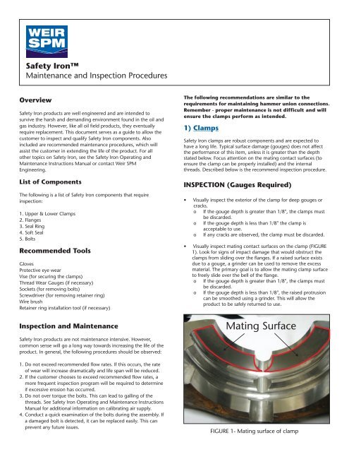
Safety IronMaintenance and Inspection ProceduresOverviewSafety Iron products are well engineered and are intended tosurvive the harsh and demanding environment found in the oil andgas industry. However, like all oil field products, they eventuallyrequire replacement. This document serves as a guide to allow thecustomer to inspect and qualify Safety Iron components. Alsoincluded are recommended maintenance procedures, which willassist the customer in extending the life of the product. For allother topics on Safety Iron, see the Safety Iron Operating andMaintenance Instructions Manual or contact <strong>Weir</strong> SPMEngineering.List of ComponentsThe following is a list of Safety Iron components that requireinspection:1. Upper & Lower Clamps2. Flanges3. Seal Ring4. Soft Seal5. BoltsRecommended ToolsGlovesProtective eye wearVise (for securing the clamps)Thread Wear Gauges (if necessary)Sockets (for removing bolts)Screwdriver (for removing retainer ring)Wire brushRetainer ring installation tool (if necessary)Inspection and MaintenanceSafety Iron products are not maintenance intensive. However,common sense will go a long way towards increasing the life of theproduct. In general, the following procedures should be observed:1. Do not exceed recommended flow rates. If this occurs, the rateof wear will increase dramatically and life span will be reduced.2. If the customer chooses to exceed recommended flow rates, amore frequent inspection program will be required to determineif excessive erosion has occurred.3. Do not over torque the bolts. This can lead to galling of thethreads. See Safety Iron Operating and Maintenance InstructionsManual for additional information on calibrating air supply.4. Conduct a quick examination of the bolts during the assembly. Ifa damaged bolt is detected, it can be replaced easily. This canprevent any future issues.The following recommendations are similar to therequirements for maintaining hammer union connections.Remember - proper maintenance is not difficult and willensure the clamps perform as intended.1) ClampsSafety Iron clamps are robust components and are expected tohave a long life. Typical surface damage (gouges) does not affectthe performance of this item, unless it is greater than the depthstated below. Focus attention on the mating contact surfaces (toensure the clamp can be properly installed) and the internalthreads. Described below is the recommend inspection procedure.INSPECTION (Gauges Required)• Visually inspect the exterior of the clamp for deep gouges orcracks.o If the gouge depth is greater than 1/8", the clamps mustbe discarded.o If the gouge depth is less than 1/8" the clamp isacceptable to use.o If any cracks are observed, the clamp must be discarded.• Visually inspect mating contact surfaces on the clamp (FIGURE1). Look for signs of impact damage that would obstruct theclamps from sliding over the flanges. If a raised surface existsdue to a gouge, a grinder can be used to remove the excessmaterial. The primary goal is to allow the mating clamp surfaceto freely slide over the bell of the flange.o If the gouge depth is greater than 1/8", the clamps mustbe discarded.o If the gouge depth is less than 1/8", the raised protrusioncan be smoothed using a grinder. This will allow theproduct to be safely returned to use.Mating SurfaceFIGURE 1- Mating surface of clamp
• Visually inspect the internal threads (only on the bottomthreaded clamp) for broken or missing threads (FIGURE 2). Ifany obvious damage is observed, the clamp must be discarded.• In addition to cracked or missing threads, constant use will alsolead to wear of the threads. This will require inspection usingthe appropriate wear gauge (see TABLE 2 for list of gauges).This no-go gauge will not thread into the internal threadsunless they are worn and require replacement. This will qualifywear of the threads that may be difficult to visually detect.• Always lubricate the threads before assembling the clamps.This will ensure proper torquing, and extend the life of theclamps and bolts.• To prevent unintentional impact damage to the clamp matingcontact surfaces, <strong>Weir</strong> SPM recommends that the upper andlower clamp halves be stored by threading the two halvestogether (FIGURE 3).WEAR GAUGE INSTRUCTIONS1. Fixture clamp within vise.2. Select appropriate wear gauge (TABLE 2).3. Attempt to thread the gauge into the internal threads.4. If the full length of the gauge will thread into the clamp threads,the clamp must be discarded.5. If the full length of the gauge will not thread onto the clampthreads, the clamp is acceptable for continued use.Remember, the gauge will only thread into the part if the internalthreads have experienced excessive wear.MAINTENTANCEThe following maintenance recommendations can increase the lifeof the product and prevent potential issues:• Debris and mud can build in the clamp threads, leading todifficulty inserting the bolt. The solution is to periodically tapthe threads (with the appropriate size tap) to remove anydebris (TABLE 1). By removing foreign material, the life of thethreads can be extended.FIGURE 3 - Safety Iron Clamps assembled for storage2) FlangesFlanges are an integral part of each Safety Iron flow component.Their lifespan will be primarily determined by the amount ofexposure to erosion. Focus attention on the seal pocket, front face,and clamp mating surfaces. Described below are the recommendedinspection procedures.Size1.5"-15K2"-15K2"-20K3"-15K3"-20K4”-10K4”-15KUndamaged ThreadsFIGURE 2 - Lowerthreaded clampTABLE 1: THREAD SIZES OF LOWER CLAMPSPart No2P259132P259162P259162P259102P252322P259222P25232Thread Size7/8"~9UNC7/8"~9UNC7/8"~9UNC1"~8UNC1-1/4"~7 UNC1"~8 UNC1-1/4"~7 UNC2INSPECTION (No Gauges Required)• Visually inspect the backside of the flange (FIGURE 4 & 5) forimpact damage or gouges. To be a concern, the gouge musthave created a protrusion of material, preventing the clampfrom freely sliding over the flange.o If the gouge depth is more than 1/4", the componentmust be discarded.o If the gouge depth is less than 1/4", the raised protrusioncan be smoothed using a grinder. This will allow theproduct to be safely returned to use.o The main concern is that no "step" or obstruction exists onthe flange that would let the clamp "hang-up" and notfully install.
BacksideofFlangeFlangeFaceSeal CavityFIGURE 4 - Flange backsideDamaged SurfaceFIGURE 6 - Flange face and seal cavity<strong>MAINTENANCE</strong>The following maintenance recommendation can increase the lifeof the product and prevent potential issues:• The seal cavity on the flange must be protected fromexcessive wear or damage. This is no different than therequirements for hammer union seal rings. Greasing theseal ring during assembly, and replacing worn soft seals isthe best method to extend the life of the seal cavity.3) Seal RingsFIGURE 5 - Damaged flange backside• Visually inspect the front face of the flange (FIGURE 6) forimpact damage or gouges. To be a concern, the gouge musthave created a protrusion, which would prevent the twomating flanges from being brought completely together.o If the gouge depth is greater than 1/4", the item must bediscarded.o If the gouge depth is less than 1/4", the raised protrusioncan be smoothed using a grinder. This will allow theproduct to be safely returned to use.• Visually inspect the seal cavity for damage (FIGURE 6). Thiswould include erosion, gouging, or deep scratches. If anydamage is observed, the component must be discarded.Seal rings are considered expendable items and will require periodicinspection. Focus attention on the seal surfaces and through-bore(FIGURE 7). Common reasons for replacement include gouges,deep scratches, and erosion damage. Described below are therecommended inspection procedures.Seal SurfaceThrough BoreFIGURE 7 - Seal RingINSPECTION (No Gauges Required)3• Remove the soft seal.• Visually inspect all seal surfaces, including under the softseal (FIGURE 7). If any erosion, impact damage, orgouges are observed, the seal ring must be discarded.• Visually inspect the through-bore. If washing is observedthe seal ring must be discarded.
4) Soft SealsSoft seals are considered expendable items (FIGURE 8) and shouldbe inspected during each assembly of the iron. If the seal appearsquestionable, it should be replaced. The maintenance for soft sealswill be similar to hammer union seals. Described below are therecommended inspection procedures.Damaged ThreadsNew ThreadsINSPECTION (No gauges required)Look for signs of damage such as tears, extrusion, or washing. Ifany damage is observed, the seal should be discarded.FIGURE 9 - Damaged and good boltsTABLE 2: LISTING OF GAUGE PART NUMBERSSIZE2"-15K3"-15K3"-20K4”-10K4”-15KRETAINERRING REMOVALTOOL2A274952A274942A274972A274942A27497CLAMPTHREAD WEARGAUGES2A274982A275002A275022A274942A27497BOLTTHREAD WEARGAUGES2A274992A275012A275032A275012A275035) BoltsFIGURE 8 - Soft SealSafety Iron bolts are designed for robust performance. They includefeatures such as cross-resistant thread design, and plated surfaces.However, like all threaded connections, they must be treated withcare and respect. Potential bolt issues include the following:1. Galling of bolt threads. This is due to over torquing orinsufficient lubricant2. Crossing of threads. This is prevented by hand rotating the boltsone (1) full turn before applying pneumatic tool.3. Impact damage to the threads. This is caused by carelessbehavior or improper storage (FIGURE 9).With proper care, Safety Iron bolts can have a reasonable lifespan. Ifthe bolts do become worn, they can easily be replaced using the<strong>Weir</strong> SPM installation tool (see maintenance section below forinstruction on installing captive bolts). Described below are therecommended inspection procedures.INSPECTION (Gauges required)• Visually inspect bolts for damaged threads. Damage includesunintentional impacts, galled threads, and missing threads. Ifany damaged threads are observed, the bolt must be discarded.• In addition to obvious thread damage, it is possible for thethreads to become worn due to daily use. This type of wear ismore difficult to detect. The most likely sign would be increased"looseness" in the makeup. Use a <strong>Weir</strong> SPM wear gauge todetermine if the threads are worn (see instructions below). Theno-go gauge should not thread on the bolt. If this occurs, thebolt must be replaced.• Visually inspect that the retainer ring holds the bolt captive.This feature is intended for convenience and prevents the boltsfrom being separated from the upper clamp halves. If the bolt isnot held captive, the retainer ring should be replaced. Thisrequires the use of the <strong>Weir</strong> SPM installation tool. Seemaintenance section below for instructions on replacing theretainer ring.WEAR GAUGE INSTRUCTIONS41. Fixture bolt by placing hex head within vise.2. Select appropriate wear gauge (TABLE 2).3. Attempt to thread the gauge onto the bolt threads.4. If the full length of the gauge will thread onto the externalthreads, the bolt must be discarded.5. If the full length of the gauge will not thread onto theexternal threads, the bolt is acceptable for continued use.
Remember, the gauge will only thread onto the part if the threadshave experienced excessive wear.<strong>MAINTENANCE</strong>The following maintenance recommendations can increase the lifeof the product and prevent potential issues:• Always lubricate bolt threads before assembly. This isimportant to prevent galling, increase the lifespan, and ensurethe bolts have the proper torque. Recommended bolt torque isbased on using lubricated bolts. A "dry" assembly will result inthe actual preload being less than is intended.• Recommended lubricants for bolt threads include generalpurposegrease or anti-seize. The use of motor oil as a lubricantis common in the field. While we do not recommend this as the"ideal" lubricant, we do acknowledge that it meets ourminimum requirements.• If bolts are difficult to thread into clamp, they may requirecleaning. This is best accomplished by using a wire brush. Drillmounted wire brushes are acceptable if care is taken not todamage the threads.• To prevent damage to the threads during storage, the upperand lower clamps should be threaded together.WARNING!DAMAGED BOLT THREADS CAN LEAD TO FALSE TORQUEREADINGS. THIS CAN MISLEAD THE TECHNICIAN TOBELIEVE THE BOLTS ARE PROPERLY INSTALLED. ALWAYSUSE COMMON SENSE WHEN ASSEMBLING <strong>SAFETY</strong> <strong>IRON</strong> - IFTHE BOLTS DON'T APPEAR TO BE FULLY ENGAGED THENTHEY PROBABLY ARE NOT!Bolt ProjectionREMEMBER - The clamps cannot be separated due to operatingpressures unless the bolts are not fully threaded into the lowerclamps.REFERENCESSafety Iron Operating and Maintenance Instructions ManualSafety Iron Operating and Maintenance Training VideoIT IS CRITICAL THAT A FINAL INSPECTION BE PERFORMEDON THE <strong>IRON</strong> AFTER COMPLETION OF THE ASSEMBLY. THERECOMMENDED INSPECTION IS FAST AND EASY AND CANBE ACCOMPLISHED IN MINUTES:1. Place hands on back side of threaded clamp and locate theend of the bolt (FIGURE 10). Use your fingers to feel thebolt end. It should be approximately flush with thebackside of the threaded clamp. If the end of the bolt isrecessed more than 1/4" into the threaded opening, thebolt may not be fully tightened.2. Repeat for each connection.3. See Safety Iron Operating and Maintenance Video foradditional information.This process will ensure that the technician locates any bolts whichwere not fully tightened. This could be due to damaged threads, orcarelessness of the technician.5
BB34AA165SIZE1.5”-15K2”-15K2”-20K3”-15K3”-20K4”-10K4”-15KCOMPLETE CLAMP KITSKIT NO. 'A' 'B' 'C' 'D' 'E' 'F'2A259302A259192A260782A259172A25405R 22A259272A25402SIZE1.5”-15K 2A256802”-15K 2A256812”-20K 2A256823”-15K 2A259293”-20K 2A260214”-10K 2A260224”-15K 2A25435R 22P25912 2P25913 2P25242 2P25243 2P25871 2P258722P25918 2P259162P252422P25904 2P25910 2P25247 2P25248 2P25903 2P252522P24728 2P252322P252342P25233 2P25903 2P252522P25921 2P25922 2P25247 2P25248 2P25874 2P259262P24728 2P25232 2P25233 2P25234 2P24735 2P24736CLAMP ONLY KITSKIT NO. 'A' 'B' 'C' 'D'2P259122P259182P259042P247282P259212P252432P259132P259162P259102P252322P259222P24728 2P252322P25899SEAL RING KITSKIT NO. 'E' 'F'2A260232A260242A260262A260272A260282A260292P252422P252422P252472P252332P252472P252332P258712P258992P259032P258742P247352P252502P25918 2P25916 2P25242 2P25243 2P26080 2P254082P252432P252432P25918 2P25916 2P25242 2P25243SIZE1.5”-15K2”-15K2”-20K3”-15K3”-20K4”-10K4”-15K2A260252P260802P259032P252482P252342P252482P252342P258722P252502P254082P252522P252522P259262P24736SCALE = 5:8SECTION2UNLES S O THER WISE NOTED7601 WYATT DRIVEDIMENSION S ARE IN INCHESSPM FT WORTH TEXAS 76108-2587fractional + 1/32Scale: NONE Drawn by: JED"B-B" lineartolSECTION "A-A".XX+.01Date: 12/01/05Approved:JDCFlow Control, Inc.SCALE = 5:8.XXX+ .005 Description:Angular tol+30'R02/022 SEE ECN #4532JED 2006R01/061 SEE ECN #4535JED 2006REV.DESCRIPTIONBYDateITEM QTY PART NO DESCRIPTIONAll diameters concentric to.010 unles s otherwise noted125654321212211“F”“E”“D”“C”“B”“A”surface roughness allmachined surfacesDO NOT SCALE DRAWINGMaterial:SOFT SEALSEAL RINGBOLT RETAINERBOLTCLAMP HALF - THREADEDCLAMP HALF - PLAINMATERIALTITLE KIT LISTINGTITLE 2<strong>SAFETY</strong> <strong>IRON</strong> - ALL SIZESDrawing No:2L25679----6
BB34AA165SIZE1.5”-15K2”-15K2”-20K3”-15K3”-20K4”-10K4”-15KCOMPLETE CLAMP KITSKIT NO. 'A' 'B' 'C' 'D' 'E' 'F'2A259302A259192A260782A259172A25405R 22A259272A25402SIZE1.5”-15K 2A256802”-15K 2A256812”-20K 2A256823”-15K 2A259293”-20K 2A260214”-10K 2A260224”-15K 2A25435R 22P25912 2P25913 2P25242 2P25243 2P25871 2P258722P25918 2P259162P252422P25904 2P25910 2P25247 2P25248 2P25903 2P252522P24728 2P252322P252342P25233 2P25903 2P252522P25921 2P25922 2P25247 2P25248 2P25874 2P259262P24728 2P25232 2P25233 2P25234 2P24735 2P24736CLAMP ONLY KITSKIT NO. 'A' 'B' 'C' 'D'2P259122P259182P259042P247282P259212P252432P259132P259162P259102P252322P259222P24728 2P252322P25899SEAL RING KITSKIT NO. 'E' 'F'2A260232A260242A260262A260272A260282A260292P252422P252422P252472P252332P252472P252332P258712P258992P259032P258742P247352P252502P25918 2P25916 2P25242 2P25243 2P26080 2P254082P252432P252432P25918 2P25916 2P25242 2P25243SIZE1.5”-15K2”-15K2”-20K3”-15K3”-20K4”-10K4”-15K2A260252P260802P259032P252482P252342P252482P252342P258722P252502P254082P252522P252522P259262P24736SCALE = 5:8SECTION2UNLES S O THER WISE NOTED7601 WYATT DRIVEDIMENSION S ARE IN INCHESSPM FT WORTH TEXAS 76108-2587fractional + 1/32Scale: NONE Drawn by: JED"B-B" lineartolSECTION "A-A".XX+.01Date: 12/01/05Approved:JDCFlow Control, Inc.SCALE = 5:8.XXX+ .005 Description:Angular tol+30'R02/022 SEE ECN #4532JED 2006R01/061 SEE ECN #4535JED 2006REV.DESCRIPTIONBYDateITEM QTY PART NO DESCRIPTIONAll diameters concentric to.010 unles s otherwise noted125654321212211“F”“E”“D”“C”“B”“A”surface roughness allmachined surfacesDO NOT SCALE DRAWINGMaterial:SOFT SEALSEAL RINGBOLT RETAINERBOLTCLAMP HALF - THREADEDCLAMP HALF - PLAINMATERIALTITLE KIT LISTINGTITLE 2<strong>SAFETY</strong> <strong>IRON</strong> - ALL SIZESDrawing No:2L25679----7
<strong>Weir</strong> SPMA World Leader in Well Service Pumps and Flow Control ProductsFort Worth, TX Red Deer, AB, CanadaHouston, TX Medicine Hat, AB, CanadaOdessa, TX Grande Prairie, AB, CanadaAlice, TX Aberdeen, ScotlandLongview, TX Dubai, UAELafayette, LA SingaporeBrighton, COJane Lew, WVSearcy, ARFor further information please contact the nearest sales office or visit www.weiroilandgas.com<strong>Weir</strong> SPM7601 Wyatt DriveFort WorthTX 76108USATel: (817) 246 2461Fax (817) 246 6324www.weiroilandgas.com© 2008 <strong>Weir</strong> SPM 05/08