Integrator's Reference Manual for Polycom HDX ... - 1 PC Network Inc
Integrator's Reference Manual for Polycom HDX ... - 1 PC Network Inc
Integrator's Reference Manual for Polycom HDX ... - 1 PC Network Inc
- No tags were found...

You also want an ePaper? Increase the reach of your titles
YUMPU automatically turns print PDFs into web optimized ePapers that Google loves.
product pic hereIntegrator’s <strong>Reference</strong> <strong>Manual</strong><strong>for</strong> <strong>Polycom</strong> <strong>HDX</strong> SystemsVersion 1.0December 2006 Edition3725-23979-001/AVersion 1.0
Trademark In<strong>for</strong>mation<strong>Polycom</strong>®, the <strong>Polycom</strong> logo design, and Vortex® are registered trademarks of <strong>Polycom</strong>, <strong>Inc</strong>., and Global ManagementSystem, MGC, People+Content, People On Content, <strong>Polycom</strong> InstantDesigner, <strong>Polycom</strong> PathNavigator,PowerCam, Siren, and VSX are trademarks of <strong>Polycom</strong>, <strong>Inc</strong>. in the United States and various other countries.VISCA is a trademark of Sony Corporation. All other trademarks are the property of their respective owners.Patent In<strong>for</strong>mationThe accompanying product is protected by one or more U.S. and <strong>for</strong>eign patents and/or pending patent applicationsheld by <strong>Polycom</strong>, <strong>Inc</strong>.© 2006 <strong>Polycom</strong>, <strong>Inc</strong>. All rights reserved.<strong>Polycom</strong> <strong>Inc</strong>.4750 Willow RoadPleasanton, CA 94588-2708USANo part of this document may be reproduced or transmitted in any <strong>for</strong>m or by any means, electronic or mechanical, <strong>for</strong>any purpose, without the express written permission of <strong>Polycom</strong>, <strong>Inc</strong>. Under the law, reproducing includes translatinginto another language or <strong>for</strong>mat.As between the parties, <strong>Polycom</strong>, <strong>Inc</strong>. retains title to, and ownership of, all proprietary rights with respect to the softwarecontained within its products. The software is protected by United States copyright laws and international treatyprovision. There<strong>for</strong>e, you must treat the software like any other copyrighted material (e.g. a book or sound recording).Every ef<strong>for</strong>t has been made to ensure that the in<strong>for</strong>mation in this manual is accurate. <strong>Polycom</strong>, <strong>Inc</strong>. is not responsible<strong>for</strong> printing or clerical errors. In<strong>for</strong>mation in this document is subject to change without notice.
Contents1 Room Integration . . . . . . . . . . . . . . . . . . . . . . . . . . . . . . . 1-1Setting Up a Room <strong>for</strong> Video Conferencing . . . . . . . . . . . . . . . . . . . . . . . . . . . . . . . . 1-1Room Layout Examples . . . . . . . . . . . . . . . . . . . . . . . . . . . . . . . . . . . . . . . . . . . . . 1-1Setting Up the Room <strong>for</strong> People On Content . . . . . . . . . . . . . . . . . . . . . . . . . . . 1-3Integrating Video . . . . . . . . . . . . . . . . . . . . . . . . . . . . . . . . . . . . . . . . . . . . . . . . . . . . . . 1-4Connecting <strong>Polycom</strong> Cameras . . . . . . . . . . . . . . . . . . . . . . . . . . . . . . . . . . . . . . . 1-5Connecting Other Video Cameras . . . . . . . . . . . . . . . . . . . . . . . . . . . . . . . . . . . 1-10Integrating Audio . . . . . . . . . . . . . . . . . . . . . . . . . . . . . . . . . . . . . . . . . . . . . . . . . . . . . 1-11Connecting a <strong>Polycom</strong> <strong>HDX</strong> System to a Vortex Mixer . . . . . . . . . . . . . . . . . 1-112 Cables . . . . . . . . . . . . . . . . . . . . . . . . . . . . . . . . . . . . . . . 2-1<strong>Network</strong> Cables . . . . . . . . . . . . . . . . . . . . . . . . . . . . . . . . . . . . . . . . . . . . . . . . . . . . . . . . 2-1CAT 5e LAN Cable . . . . . . . . . . . . . . . . . . . . . . . . . . . . . . . . . . . . . . . . . . . . . . . . . 2-1ISDN Cable . . . . . . . . . . . . . . . . . . . . . . . . . . . . . . . . . . . . . . . . . . . . . . . . . . . . . . . 2-2Analog Telephone (POTS) Cable . . . . . . . . . . . . . . . . . . . . . . . . . . . . . . . . . . . . . 2-3V.35/RS-449/RS-530 Serial Adapter . . . . . . . . . . . . . . . . . . . . . . . . . . . . . . . . . . 2-4V.35 NIC Cable . . . . . . . . . . . . . . . . . . . . . . . . . . . . . . . . . . . . . . . . . . . . . . . . . . . . 2-5V.35 and RS-366 Serial Cable . . . . . . . . . . . . . . . . . . . . . . . . . . . . . . . . . . . . . . . . . 2-6RS-449 and RS-366 Serial Cable . . . . . . . . . . . . . . . . . . . . . . . . . . . . . . . . . . . . . . 2-7RS-530 with RS-366 Serial Cable . . . . . . . . . . . . . . . . . . . . . . . . . . . . . . . . . . . . . . 2-8Video and Camera Cables . . . . . . . . . . . . . . . . . . . . . . . . . . . . . . . . . . . . . . . . . . . . . . . 2-9S-Video Cable . . . . . . . . . . . . . . . . . . . . . . . . . . . . . . . . . . . . . . . . . . . . . . . . . . . . . 2-9BNC to S-Video Cable . . . . . . . . . . . . . . . . . . . . . . . . . . . . . . . . . . . . . . . . . . . . . 2-10BNC to S-Video Adapter . . . . . . . . . . . . . . . . . . . . . . . . . . . . . . . . . . . . . . . . . . . 2-11DVI to VGA Monitor Cable . . . . . . . . . . . . . . . . . . . . . . . . . . . . . . . . . . . . . . . . . 2-12HDMI Monitor Cable . . . . . . . . . . . . . . . . . . . . . . . . . . . . . . . . . . . . . . . . . . . . . . 2-13BNC Monitor Adapter Cable . . . . . . . . . . . . . . . . . . . . . . . . . . . . . . . . . . . . . . . 2-14DVI-D Monitor Cable . . . . . . . . . . . . . . . . . . . . . . . . . . . . . . . . . . . . . . . . . . . . . . 2-15HDCI Analog Camera Cable . . . . . . . . . . . . . . . . . . . . . . . . . . . . . . . . . . . . . . . . 2-16HDCI Camera Break-Out Cable . . . . . . . . . . . . . . . . . . . . . . . . . . . . . . . . . . . . . 2-17VCR/DVD Composite Cable . . . . . . . . . . . . . . . . . . . . . . . . . . . . . . . . . . . . . . . 2-18Composite Video Cable . . . . . . . . . . . . . . . . . . . . . . . . . . . . . . . . . . . . . . . . . . . . 2-19PowerCam Plus Primary Cable . . . . . . . . . . . . . . . . . . . . . . . . . . . . . . . . . . . . . 2-20HDCI PowerCam Plus Adapter Cable . . . . . . . . . . . . . . . . . . . . . . . . . . . . . . . 2-21HDCI VISCA Adapter Cable . . . . . . . . . . . . . . . . . . . . . . . . . . . . . . . . . . . . . . . . 2-22iii
Integrator’s <strong>Reference</strong> <strong>Manual</strong> <strong>for</strong> <strong>Polycom</strong> <strong>HDX</strong> SystemsHDCI Sony VISCA Adapter Cable . . . . . . . . . . . . . . . . . . . . . . . . . . . . . . . . . . . 2-23PowerCam Primary Camera Cable . . . . . . . . . . . . . . . . . . . . . . . . . . . . . . . . . . 2-24PowerCam Break-Out Cable . . . . . . . . . . . . . . . . . . . . . . . . . . . . . . . . . . . . . . . . 2-25PowerCam Plus/VISCA Control Cable . . . . . . . . . . . . . . . . . . . . . . . . . . . . . . 2-26PowerCam/VISCA Control Cable . . . . . . . . . . . . . . . . . . . . . . . . . . . . . . . . . . 2-28Audio Cables . . . . . . . . . . . . . . . . . . . . . . . . . . . . . . . . . . . . . . . . . . . . . . . . . . . . . . . . . 2-29<strong>Polycom</strong> <strong>HDX</strong> Microphone Array Cable . . . . . . . . . . . . . . . . . . . . . . . . . . . . . . 2-29<strong>Polycom</strong> <strong>HDX</strong> Microphone Array Cable Adapter . . . . . . . . . . . . . . . . . . . . . . 2-30Custom Cabling <strong>for</strong> <strong>Polycom</strong> <strong>HDX</strong> Microphones . . . . . . . . . . . . . . . . . . . . . . 2-31Audio Adapter Cable . . . . . . . . . . . . . . . . . . . . . . . . . . . . . . . . . . . . . . . . . . . . . . 2-34Audio Cable . . . . . . . . . . . . . . . . . . . . . . . . . . . . . . . . . . . . . . . . . . . . . . . . . . . . . . 2-35Vortex Cable . . . . . . . . . . . . . . . . . . . . . . . . . . . . . . . . . . . . . . . . . . . . . . . . . . . . . 2-363.5mm Screw Cage Connector . . . . . . . . . . . . . . . . . . . . . . . . . . . . . . . . . . . . . . 2-37Subwoofer Volume Attenuator . . . . . . . . . . . . . . . . . . . . . . . . . . . . . . . . . . . . . . 2-38Serial (RS-232) Cables . . . . . . . . . . . . . . . . . . . . . . . . . . . . . . . . . . . . . . . . . . . . . . . . . . 2-39RS-232 Cable . . . . . . . . . . . . . . . . . . . . . . . . . . . . . . . . . . . . . . . . . . . . . . . . . . . . . 2-39Null Modem Adapter . . . . . . . . . . . . . . . . . . . . . . . . . . . . . . . . . . . . . . . . . . . . . . 2-413 Using the API . . . . . . . . . . . . . . . . . . . . . . . . . . . . . . . . . . 3-1Using the API with an RS-232 Interface . . . . . . . . . . . . . . . . . . . . . . . . . . . . . . . . . . . 3-1Configuring the RS-232 Interface . . . . . . . . . . . . . . . . . . . . . . . . . . . . . . . . . . . . 3-2Starting an API Session via an RS-232 Interface . . . . . . . . . . . . . . . . . . . . . . . . . 3-2Using the API with a LAN Connection . . . . . . . . . . . . . . . . . . . . . . . . . . . . . . . . . . . . 3-3Using the API Controller Code . . . . . . . . . . . . . . . . . . . . . . . . . . . . . . . . . . . . . . . . . . . 3-34 System Commands . . . . . . . . . . . . . . . . . . . . . . . . . . . . . . 4-1About the API Commands . . . . . . . . . . . . . . . . . . . . . . . . . . . . . . . . . . . . . . . . . . . . . . 4-2Syntax Conventions . . . . . . . . . . . . . . . . . . . . . . . . . . . . . . . . . . . . . . . . . . . . . . . . 4-2Availability of Commands . . . . . . . . . . . . . . . . . . . . . . . . . . . . . . . . . . . . . . . . . . 4-2! . . . . . . . . . . . . . . . . . . . . . . . . . . . . . . . . . . . . . . . . . . . . . . . . . . . . . . . . . . . . . . . . . . . . . 4-3abk . . . . . . . . . . . . . . . . . . . . . . . . . . . . . . . . . . . . . . . . . . . . . . . . . . . . . . . . . . . . . . . . . . . 4-4addressdisplayedingab . . . . . . . . . . . . . . . . . . . . . . . . . . . . . . . . . . . . . . . . . . . . . . . . . 4-6adminpassword . . . . . . . . . . . . . . . . . . . . . . . . . . . . . . . . . . . . . . . . . . . . . . . . . . . . . . . . 4-7advnetstats . . . . . . . . . . . . . . . . . . . . . . . . . . . . . . . . . . . . . . . . . . . . . . . . . . . . . . . . . . . . 4-8alertusertone . . . . . . . . . . . . . . . . . . . . . . . . . . . . . . . . . . . . . . . . . . . . . . . . . . . . . . . . . . 4-9alertvideotone . . . . . . . . . . . . . . . . . . . . . . . . . . . . . . . . . . . . . . . . . . . . . . . . . . . . . . . . 4-10all register . . . . . . . . . . . . . . . . . . . . . . . . . . . . . . . . . . . . . . . . . . . . . . . . . . . . . . . . . . . . 4-11all unregister . . . . . . . . . . . . . . . . . . . . . . . . . . . . . . . . . . . . . . . . . . . . . . . . . . . . . . . . . 4-12allowabkchanges . . . . . . . . . . . . . . . . . . . . . . . . . . . . . . . . . . . . . . . . . . . . . . . . . . . . . . 4-13allowcamerapresetssetup . . . . . . . . . . . . . . . . . . . . . . . . . . . . . . . . . . . . . . . . . . . . . . 4-14allowmixedcalls . . . . . . . . . . . . . . . . . . . . . . . . . . . . . . . . . . . . . . . . . . . . . . . . . . . . . . . 4-15allowusersetup . . . . . . . . . . . . . . . . . . . . . . . . . . . . . . . . . . . . . . . . . . . . . . . . . . . . . . . 4-16answer . . . . . . . . . . . . . . . . . . . . . . . . . . . . . . . . . . . . . . . . . . . . . . . . . . . . . . . . . . . . . . . 4-17areacode . . . . . . . . . . . . . . . . . . . . . . . . . . . . . . . . . . . . . . . . . . . . . . . . . . . . . . . . . . . . . 4-18autoanswer . . . . . . . . . . . . . . . . . . . . . . . . . . . . . . . . . . . . . . . . . . . . . . . . . . . . . . . . . . . 4-19iv
Contentsbacklightcompensation . . . . . . . . . . . . . . . . . . . . . . . . . . . . . . . . . . . . . . . . . . . . . . . . 4-20basicmode . . . . . . . . . . . . . . . . . . . . . . . . . . . . . . . . . . . . . . . . . . . . . . . . . . . . . . . . . . . 4-21bri1enable, bri2enable, bri3enable, bri4enable . . . . . . . . . . . . . . . . . . . . . . . . . . . . . 4-22briallenable . . . . . . . . . . . . . . . . . . . . . . . . . . . . . . . . . . . . . . . . . . . . . . . . . . . . . . . . . . . 4-23button . . . . . . . . . . . . . . . . . . . . . . . . . . . . . . . . . . . . . . . . . . . . . . . . . . . . . . . . . . . . . . . 4-24calldetailreport . . . . . . . . . . . . . . . . . . . . . . . . . . . . . . . . . . . . . . . . . . . . . . . . . . . . . . . 4-27callencryption (deprecated) . . . . . . . . . . . . . . . . . . . . . . . . . . . . . . . . . . . . . . . . . . . . . 4-28callinfo . . . . . . . . . . . . . . . . . . . . . . . . . . . . . . . . . . . . . . . . . . . . . . . . . . . . . . . . . . . . . . 4-29callstate . . . . . . . . . . . . . . . . . . . . . . . . . . . . . . . . . . . . . . . . . . . . . . . . . . . . . . . . . . . . . . 4-30callstats . . . . . . . . . . . . . . . . . . . . . . . . . . . . . . . . . . . . . . . . . . . . . . . . . . . . . . . . . . . . . . 4-31camera . . . . . . . . . . . . . . . . . . . . . . . . . . . . . . . . . . . . . . . . . . . . . . . . . . . . . . . . . . . . . . . 4-32cameradirection . . . . . . . . . . . . . . . . . . . . . . . . . . . . . . . . . . . . . . . . . . . . . . . . . . . . . . . 4-35camerainput . . . . . . . . . . . . . . . . . . . . . . . . . . . . . . . . . . . . . . . . . . . . . . . . . . . . . . . . . . 4-36chaircontrol . . . . . . . . . . . . . . . . . . . . . . . . . . . . . . . . . . . . . . . . . . . . . . . . . . . . . . . . . . 4-37colorbar . . . . . . . . . . . . . . . . . . . . . . . . . . . . . . . . . . . . . . . . . . . . . . . . . . . . . . . . . . . . . . 4-39cmdecho . . . . . . . . . . . . . . . . . . . . . . . . . . . . . . . . . . . . . . . . . . . . . . . . . . . . . . . . . . . . . 4-40configchange (deprecated) . . . . . . . . . . . . . . . . . . . . . . . . . . . . . . . . . . . . . . . . . . . . . 4-41configdisplay . . . . . . . . . . . . . . . . . . . . . . . . . . . . . . . . . . . . . . . . . . . . . . . . . . . . . . . . . 4-42configpresentation . . . . . . . . . . . . . . . . . . . . . . . . . . . . . . . . . . . . . . . . . . . . . . . . . . . . 4-43confirmdiradd . . . . . . . . . . . . . . . . . . . . . . . . . . . . . . . . . . . . . . . . . . . . . . . . . . . . . . . . 4-45confirmdirdel . . . . . . . . . . . . . . . . . . . . . . . . . . . . . . . . . . . . . . . . . . . . . . . . . . . . . . . . . 4-46contentauto . . . . . . . . . . . . . . . . . . . . . . . . . . . . . . . . . . . . . . . . . . . . . . . . . . . . . . . . . . 4-47country . . . . . . . . . . . . . . . . . . . . . . . . . . . . . . . . . . . . . . . . . . . . . . . . . . . . . . . . . . . . . . 4-48cts . . . . . . . . . . . . . . . . . . . . . . . . . . . . . . . . . . . . . . . . . . . . . . . . . . . . . . . . . . . . . . . . . . . 4-49daylightsavings . . . . . . . . . . . . . . . . . . . . . . . . . . . . . . . . . . . . . . . . . . . . . . . . . . . . . . . 4-50dcd . . . . . . . . . . . . . . . . . . . . . . . . . . . . . . . . . . . . . . . . . . . . . . . . . . . . . . . . . . . . . . . . . . 4-51dcdfilter . . . . . . . . . . . . . . . . . . . . . . . . . . . . . . . . . . . . . . . . . . . . . . . . . . . . . . . . . . . . . 4-52defaultgateway . . . . . . . . . . . . . . . . . . . . . . . . . . . . . . . . . . . . . . . . . . . . . . . . . . . . . . . 4-53dhcp . . . . . . . . . . . . . . . . . . . . . . . . . . . . . . . . . . . . . . . . . . . . . . . . . . . . . . . . . . . . . . . . 4-54dial . . . . . . . . . . . . . . . . . . . . . . . . . . . . . . . . . . . . . . . . . . . . . . . . . . . . . . . . . . . . . . . . . . 4-55dialchannels . . . . . . . . . . . . . . . . . . . . . . . . . . . . . . . . . . . . . . . . . . . . . . . . . . . . . . . . . . 4-57dialingdisplay . . . . . . . . . . . . . . . . . . . . . . . . . . . . . . . . . . . . . . . . . . . . . . . . . . . . . . . . 4-58diffservaudio, diffservfecc, diffservvideo . . . . . . . . . . . . . . . . . . . . . . . . . . . . . . . . . 4-59dir . . . . . . . . . . . . . . . . . . . . . . . . . . . . . . . . . . . . . . . . . . . . . . . . . . . . . . . . . . . . . . . . . . 4-60directory . . . . . . . . . . . . . . . . . . . . . . . . . . . . . . . . . . . . . . . . . . . . . . . . . . . . . . . . . . . . . 4-61display (deprecated) . . . . . . . . . . . . . . . . . . . . . . . . . . . . . . . . . . . . . . . . . . . . . . . . . . . 4-62displayglobaladdresses . . . . . . . . . . . . . . . . . . . . . . . . . . . . . . . . . . . . . . . . . . . . . . . . 4-63displaygraphics . . . . . . . . . . . . . . . . . . . . . . . . . . . . . . . . . . . . . . . . . . . . . . . . . . . . . . . 4-64displayipext . . . . . . . . . . . . . . . . . . . . . . . . . . . . . . . . . . . . . . . . . . . . . . . . . . . . . . . . . . 4-65displayipisdninfo (deprecated) . . . . . . . . . . . . . . . . . . . . . . . . . . . . . . . . . . . . . . . . . . 4-66displayparams . . . . . . . . . . . . . . . . . . . . . . . . . . . . . . . . . . . . . . . . . . . . . . . . . . . . . . . . 4-67dns . . . . . . . . . . . . . . . . . . . . . . . . . . . . . . . . . . . . . . . . . . . . . . . . . . . . . . . . . . . . . . . . . . 4-68dsr . . . . . . . . . . . . . . . . . . . . . . . . . . . . . . . . . . . . . . . . . . . . . . . . . . . . . . . . . . . . . . . . . . 4-69dsranswer . . . . . . . . . . . . . . . . . . . . . . . . . . . . . . . . . . . . . . . . . . . . . . . . . . . . . . . . . . . . 4-70dtr . . . . . . . . . . . . . . . . . . . . . . . . . . . . . . . . . . . . . . . . . . . . . . . . . . . . . . . . . . . . . . . . . . 4-71dualmonitor . . . . . . . . . . . . . . . . . . . . . . . . . . . . . . . . . . . . . . . . . . . . . . . . . . . . . . . . . . 4-72v
Integrator’s <strong>Reference</strong> <strong>Manual</strong> <strong>for</strong> <strong>Polycom</strong> <strong>HDX</strong> Systemsdynamicbandwidth . . . . . . . . . . . . . . . . . . . . . . . . . . . . . . . . . . . . . . . . . . . . . . . . . . . 4-73e164ext . . . . . . . . . . . . . . . . . . . . . . . . . . . . . . . . . . . . . . . . . . . . . . . . . . . . . . . . . . . . . . 4-74echo . . . . . . . . . . . . . . . . . . . . . . . . . . . . . . . . . . . . . . . . . . . . . . . . . . . . . . . . . . . . . . . . . 4-75echocanceller . . . . . . . . . . . . . . . . . . . . . . . . . . . . . . . . . . . . . . . . . . . . . . . . . . . . . . . . . 4-76echocancellerred . . . . . . . . . . . . . . . . . . . . . . . . . . . . . . . . . . . . . . . . . . . . . . . . . . . . . . 4-77echocancellerwhite . . . . . . . . . . . . . . . . . . . . . . . . . . . . . . . . . . . . . . . . . . . . . . . . . . . . 4-78enablefirewalltraversal . . . . . . . . . . . . . . . . . . . . . . . . . . . . . . . . . . . . . . . . . . . . . . . . . 4-79enablersvp . . . . . . . . . . . . . . . . . . . . . . . . . . . . . . . . . . . . . . . . . . . . . . . . . . . . . . . . . . . 4-80enablesnmp . . . . . . . . . . . . . . . . . . . . . . . . . . . . . . . . . . . . . . . . . . . . . . . . . . . . . . . . . . 4-81encryption . . . . . . . . . . . . . . . . . . . . . . . . . . . . . . . . . . . . . . . . . . . . . . . . . . . . . . . . . . . 4-82exit . . . . . . . . . . . . . . . . . . . . . . . . . . . . . . . . . . . . . . . . . . . . . . . . . . . . . . . . . . . . . . . . . . 4-83farcontrolnearcamera . . . . . . . . . . . . . . . . . . . . . . . . . . . . . . . . . . . . . . . . . . . . . . . . . . 4-84farnametimedisplay . . . . . . . . . . . . . . . . . . . . . . . . . . . . . . . . . . . . . . . . . . . . . . . . . . . 4-85flash . . . . . . . . . . . . . . . . . . . . . . . . . . . . . . . . . . . . . . . . . . . . . . . . . . . . . . . . . . . . . . . . . 4-86gabk . . . . . . . . . . . . . . . . . . . . . . . . . . . . . . . . . . . . . . . . . . . . . . . . . . . . . . . . . . . . . . . . . 4-87gabpassword . . . . . . . . . . . . . . . . . . . . . . . . . . . . . . . . . . . . . . . . . . . . . . . . . . . . . . . . . 4-88gabserverip . . . . . . . . . . . . . . . . . . . . . . . . . . . . . . . . . . . . . . . . . . . . . . . . . . . . . . . . . . 4-89gatekeeperip . . . . . . . . . . . . . . . . . . . . . . . . . . . . . . . . . . . . . . . . . . . . . . . . . . . . . . . . . 4-90gatewayareacode . . . . . . . . . . . . . . . . . . . . . . . . . . . . . . . . . . . . . . . . . . . . . . . . . . . . . . 4-91gatewaycountrycode . . . . . . . . . . . . . . . . . . . . . . . . . . . . . . . . . . . . . . . . . . . . . . . . . . 4-92gatewayext . . . . . . . . . . . . . . . . . . . . . . . . . . . . . . . . . . . . . . . . . . . . . . . . . . . . . . . . . . . 4-93gatewaynumber . . . . . . . . . . . . . . . . . . . . . . . . . . . . . . . . . . . . . . . . . . . . . . . . . . . . . . 4-94gatewaynumbertype . . . . . . . . . . . . . . . . . . . . . . . . . . . . . . . . . . . . . . . . . . . . . . . . . . . 4-95gendial . . . . . . . . . . . . . . . . . . . . . . . . . . . . . . . . . . . . . . . . . . . . . . . . . . . . . . . . . . . . . . 4-96gendialtonepots (deprecated) . . . . . . . . . . . . . . . . . . . . . . . . . . . . . . . . . . . . . . . . . . . 4-97generatetone . . . . . . . . . . . . . . . . . . . . . . . . . . . . . . . . . . . . . . . . . . . . . . . . . . . . . . . . . 4-98get screen . . . . . . . . . . . . . . . . . . . . . . . . . . . . . . . . . . . . . . . . . . . . . . . . . . . . . . . . . . . . 4-99getcallstate (deprecated) . . . . . . . . . . . . . . . . . . . . . . . . . . . . . . . . . . . . . . . . . . . . . . 4-100gmscity . . . . . . . . . . . . . . . . . . . . . . . . . . . . . . . . . . . . . . . . . . . . . . . . . . . . . . . . . . . . . 4-101gmscontactemail . . . . . . . . . . . . . . . . . . . . . . . . . . . . . . . . . . . . . . . . . . . . . . . . . . . . . 4-102gmscontactfax . . . . . . . . . . . . . . . . . . . . . . . . . . . . . . . . . . . . . . . . . . . . . . . . . . . . . . . 4-103gmscontactnumber . . . . . . . . . . . . . . . . . . . . . . . . . . . . . . . . . . . . . . . . . . . . . . . . . . . 4-104gmscontactperson . . . . . . . . . . . . . . . . . . . . . . . . . . . . . . . . . . . . . . . . . . . . . . . . . . . . 4-105gmscountry . . . . . . . . . . . . . . . . . . . . . . . . . . . . . . . . . . . . . . . . . . . . . . . . . . . . . . . . . 4-106gmsstate . . . . . . . . . . . . . . . . . . . . . . . . . . . . . . . . . . . . . . . . . . . . . . . . . . . . . . . . . . . . 4-107gmstechsupport . . . . . . . . . . . . . . . . . . . . . . . . . . . . . . . . . . . . . . . . . . . . . . . . . . . . . . 4-108gmsurl . . . . . . . . . . . . . . . . . . . . . . . . . . . . . . . . . . . . . . . . . . . . . . . . . . . . . . . . . . . . . . 4-109h239enable . . . . . . . . . . . . . . . . . . . . . . . . . . . . . . . . . . . . . . . . . . . . . . . . . . . . . . . . . . 4-110h323name . . . . . . . . . . . . . . . . . . . . . . . . . . . . . . . . . . . . . . . . . . . . . . . . . . . . . . . . . . . 4-111h331audiomode . . . . . . . . . . . . . . . . . . . . . . . . . . . . . . . . . . . . . . . . . . . . . . . . . . . . . . 4-112h331dualstream . . . . . . . . . . . . . . . . . . . . . . . . . . . . . . . . . . . . . . . . . . . . . . . . . . . . . . 4-113h331framerate . . . . . . . . . . . . . . . . . . . . . . . . . . . . . . . . . . . . . . . . . . . . . . . . . . . . . . . 4-114h331video<strong>for</strong>mat . . . . . . . . . . . . . . . . . . . . . . . . . . . . . . . . . . . . . . . . . . . . . . . . . . . . . 4-115h331videoprotocol . . . . . . . . . . . . . . . . . . . . . . . . . . . . . . . . . . . . . . . . . . . . . . . . . . . 4-116hangup . . . . . . . . . . . . . . . . . . . . . . . . . . . . . . . . . . . . . . . . . . . . . . . . . . . . . . . . . . . . . 4-117help . . . . . . . . . . . . . . . . . . . . . . . . . . . . . . . . . . . . . . . . . . . . . . . . . . . . . . . . . . . . . . . . 4-118vi
Contentshistory . . . . . . . . . . . . . . . . . . . . . . . . . . . . . . . . . . . . . . . . . . . . . . . . . . . . . . . . . . . . . . 4-119homecallquality . . . . . . . . . . . . . . . . . . . . . . . . . . . . . . . . . . . . . . . . . . . . . . . . . . . . . . 4-120homemultipoint . . . . . . . . . . . . . . . . . . . . . . . . . . . . . . . . . . . . . . . . . . . . . . . . . . . . . 4-121homerecentcalls . . . . . . . . . . . . . . . . . . . . . . . . . . . . . . . . . . . . . . . . . . . . . . . . . . . . . . 4-122homesystem . . . . . . . . . . . . . . . . . . . . . . . . . . . . . . . . . . . . . . . . . . . . . . . . . . . . . . . . . 4-123homesystemname . . . . . . . . . . . . . . . . . . . . . . . . . . . . . . . . . . . . . . . . . . . . . . . . . . . . 4-124hostname . . . . . . . . . . . . . . . . . . . . . . . . . . . . . . . . . . . . . . . . . . . . . . . . . . . . . . . . . . . 4-125ipaddress . . . . . . . . . . . . . . . . . . . . . . . . . . . . . . . . . . . . . . . . . . . . . . . . . . . . . . . . . . . 4-126ipdialspeed . . . . . . . . . . . . . . . . . . . . . . . . . . . . . . . . . . . . . . . . . . . . . . . . . . . . . . . . . . 4-127ipisdninfo . . . . . . . . . . . . . . . . . . . . . . . . . . . . . . . . . . . . . . . . . . . . . . . . . . . . . . . . . . . 4-128ipprecaudio, ipprecfecc, ipprecvideo . . . . . . . . . . . . . . . . . . . . . . . . . . . . . . . . . . . . 4-129ipstat . . . . . . . . . . . . . . . . . . . . . . . . . . . . . . . . . . . . . . . . . . . . . . . . . . . . . . . . . . . . . . . 4-130isdnareacode . . . . . . . . . . . . . . . . . . . . . . . . . . . . . . . . . . . . . . . . . . . . . . . . . . . . . . . . 4-131isdncountrycode . . . . . . . . . . . . . . . . . . . . . . . . . . . . . . . . . . . . . . . . . . . . . . . . . . . . . 4-132isdndialingprefix . . . . . . . . . . . . . . . . . . . . . . . . . . . . . . . . . . . . . . . . . . . . . . . . . . . . . 4-133isdndialspeed . . . . . . . . . . . . . . . . . . . . . . . . . . . . . . . . . . . . . . . . . . . . . . . . . . . . . . . . 4-134isdnnum . . . . . . . . . . . . . . . . . . . . . . . . . . . . . . . . . . . . . . . . . . . . . . . . . . . . . . . . . . . . 4-135isdnswitch . . . . . . . . . . . . . . . . . . . . . . . . . . . . . . . . . . . . . . . . . . . . . . . . . . . . . . . . . . 4-136keypadaudioconf . . . . . . . . . . . . . . . . . . . . . . . . . . . . . . . . . . . . . . . . . . . . . . . . . . . . 4-137language . . . . . . . . . . . . . . . . . . . . . . . . . . . . . . . . . . . . . . . . . . . . . . . . . . . . . . . . . . . . 4-138lanport . . . . . . . . . . . . . . . . . . . . . . . . . . . . . . . . . . . . . . . . . . . . . . . . . . . . . . . . . . . . . 4-139linestate . . . . . . . . . . . . . . . . . . . . . . . . . . . . . . . . . . . . . . . . . . . . . . . . . . . . . . . . . . . . . 4-140listen . . . . . . . . . . . . . . . . . . . . . . . . . . . . . . . . . . . . . . . . . . . . . . . . . . . . . . . . . . . . . . . 4-141localdatetime . . . . . . . . . . . . . . . . . . . . . . . . . . . . . . . . . . . . . . . . . . . . . . . . . . . . . . . . 4-142marqueedisplaytext . . . . . . . . . . . . . . . . . . . . . . . . . . . . . . . . . . . . . . . . . . . . . . . . . . 4-143maxgabinternationalcallspeed . . . . . . . . . . . . . . . . . . . . . . . . . . . . . . . . . . . . . . . . . 4-144maxgabinternetcallspeed . . . . . . . . . . . . . . . . . . . . . . . . . . . . . . . . . . . . . . . . . . . . . . 4-145maxgabisdncallspeed . . . . . . . . . . . . . . . . . . . . . . . . . . . . . . . . . . . . . . . . . . . . . . . . . 4-146maxtimeincall . . . . . . . . . . . . . . . . . . . . . . . . . . . . . . . . . . . . . . . . . . . . . . . . . . . . . . . 4-147mcupassword . . . . . . . . . . . . . . . . . . . . . . . . . . . . . . . . . . . . . . . . . . . . . . . . . . . . . . . 4-148meetingpassword . . . . . . . . . . . . . . . . . . . . . . . . . . . . . . . . . . . . . . . . . . . . . . . . . . . . 4-149monitor1 (deprecated) . . . . . . . . . . . . . . . . . . . . . . . . . . . . . . . . . . . . . . . . . . . . . . . . 4-150monitor1screensaverouput . . . . . . . . . . . . . . . . . . . . . . . . . . . . . . . . . . . . . . . . . . . . 4-151monitor2 (deprecated) . . . . . . . . . . . . . . . . . . . . . . . . . . . . . . . . . . . . . . . . . . . . . . . . 4-152monitor2screensaverouput . . . . . . . . . . . . . . . . . . . . . . . . . . . . . . . . . . . . . . . . . . . . 4-153mpautoanswer . . . . . . . . . . . . . . . . . . . . . . . . . . . . . . . . . . . . . . . . . . . . . . . . . . . . . . . 4-154mpmode . . . . . . . . . . . . . . . . . . . . . . . . . . . . . . . . . . . . . . . . . . . . . . . . . . . . . . . . . . . . 4-155mtumode . . . . . . . . . . . . . . . . . . . . . . . . . . . . . . . . . . . . . . . . . . . . . . . . . . . . . . . . . . . 4-156mtusize . . . . . . . . . . . . . . . . . . . . . . . . . . . . . . . . . . . . . . . . . . . . . . . . . . . . . . . . . . . . . 4-157mute . . . . . . . . . . . . . . . . . . . . . . . . . . . . . . . . . . . . . . . . . . . . . . . . . . . . . . . . . . . . . . . 4-158muteautoanswer . . . . . . . . . . . . . . . . . . . . . . . . . . . . . . . . . . . . . . . . . . . . . . . . . . . . . 4-159natconfig . . . . . . . . . . . . . . . . . . . . . . . . . . . . . . . . . . . . . . . . . . . . . . . . . . . . . . . . . . . . 4-160nath323compatible . . . . . . . . . . . . . . . . . . . . . . . . . . . . . . . . . . . . . . . . . . . . . . . . . . . 4-161nearloop . . . . . . . . . . . . . . . . . . . . . . . . . . . . . . . . . . . . . . . . . . . . . . . . . . . . . . . . . . . . 4-162netstats . . . . . . . . . . . . . . . . . . . . . . . . . . . . . . . . . . . . . . . . . . . . . . . . . . . . . . . . . . . . . 4-163nonotify . . . . . . . . . . . . . . . . . . . . . . . . . . . . . . . . . . . . . . . . . . . . . . . . . . . . . . . . . . . . 4-164vii
Integrator’s <strong>Reference</strong> <strong>Manual</strong> <strong>for</strong> <strong>Polycom</strong> <strong>HDX</strong> Systemsnotify . . . . . . . . . . . . . . . . . . . . . . . . . . . . . . . . . . . . . . . . . . . . . . . . . . . . . . . . . . . . . . . 4-165ntpmode . . . . . . . . . . . . . . . . . . . . . . . . . . . . . . . . . . . . . . . . . . . . . . . . . . . . . . . . . . . . 4-168ntpserver . . . . . . . . . . . . . . . . . . . . . . . . . . . . . . . . . . . . . . . . . . . . . . . . . . . . . . . . . . . 4-169numdigitsdid . . . . . . . . . . . . . . . . . . . . . . . . . . . . . . . . . . . . . . . . . . . . . . . . . . . . . . . . 4-170numdigitsext . . . . . . . . . . . . . . . . . . . . . . . . . . . . . . . . . . . . . . . . . . . . . . . . . . . . . . . . 4-171pause . . . . . . . . . . . . . . . . . . . . . . . . . . . . . . . . . . . . . . . . . . . . . . . . . . . . . . . . . . . . . . . 4-172phone . . . . . . . . . . . . . . . . . . . . . . . . . . . . . . . . . . . . . . . . . . . . . . . . . . . . . . . . . . . . . . 4-173pip . . . . . . . . . . . . . . . . . . . . . . . . . . . . . . . . . . . . . . . . . . . . . . . . . . . . . . . . . . . . . . . . . 4-174popupinfo . . . . . . . . . . . . . . . . . . . . . . . . . . . . . . . . . . . . . . . . . . . . . . . . . . . . . . . . . . . 4-175preset . . . . . . . . . . . . . . . . . . . . . . . . . . . . . . . . . . . . . . . . . . . . . . . . . . . . . . . . . . . . . . . 4-176pricallbycall . . . . . . . . . . . . . . . . . . . . . . . . . . . . . . . . . . . . . . . . . . . . . . . . . . . . . . . . . 4-177prichannel . . . . . . . . . . . . . . . . . . . . . . . . . . . . . . . . . . . . . . . . . . . . . . . . . . . . . . . . . . 4-178pricsu . . . . . . . . . . . . . . . . . . . . . . . . . . . . . . . . . . . . . . . . . . . . . . . . . . . . . . . . . . . . . . 4-180pridialchannels . . . . . . . . . . . . . . . . . . . . . . . . . . . . . . . . . . . . . . . . . . . . . . . . . . . . . . 4-181priintlprefix . . . . . . . . . . . . . . . . . . . . . . . . . . . . . . . . . . . . . . . . . . . . . . . . . . . . . . . . . 4-182prilinebuildout . . . . . . . . . . . . . . . . . . . . . . . . . . . . . . . . . . . . . . . . . . . . . . . . . . . . . . 4-183prilinesignal . . . . . . . . . . . . . . . . . . . . . . . . . . . . . . . . . . . . . . . . . . . . . . . . . . . . . . . . . 4-184prinumberingplan . . . . . . . . . . . . . . . . . . . . . . . . . . . . . . . . . . . . . . . . . . . . . . . . . . . . 4-185prioutsideline . . . . . . . . . . . . . . . . . . . . . . . . . . . . . . . . . . . . . . . . . . . . . . . . . . . . . . . . 4-186priswitch . . . . . . . . . . . . . . . . . . . . . . . . . . . . . . . . . . . . . . . . . . . . . . . . . . . . . . . . . . . . 4-187reboot . . . . . . . . . . . . . . . . . . . . . . . . . . . . . . . . . . . . . . . . . . . . . . . . . . . . . . . . . . . . . . 4-188recentcalls . . . . . . . . . . . . . . . . . . . . . . . . . . . . . . . . . . . . . . . . . . . . . . . . . . . . . . . . . . . 4-189registerall . . . . . . . . . . . . . . . . . . . . . . . . . . . . . . . . . . . . . . . . . . . . . . . . . . . . . . . . . . . 4-190registerthissystem . . . . . . . . . . . . . . . . . . . . . . . . . . . . . . . . . . . . . . . . . . . . . . . . . . . . 4-191remotecontrol . . . . . . . . . . . . . . . . . . . . . . . . . . . . . . . . . . . . . . . . . . . . . . . . . . . . . . . 4-192remotemonenable . . . . . . . . . . . . . . . . . . . . . . . . . . . . . . . . . . . . . . . . . . . . . . . . . . . . 4-194repeat . . . . . . . . . . . . . . . . . . . . . . . . . . . . . . . . . . . . . . . . . . . . . . . . . . . . . . . . . . . . . . 4-195requireacctnumtodial . . . . . . . . . . . . . . . . . . . . . . . . . . . . . . . . . . . . . . . . . . . . . . . . . 4-196roomphonenumber . . . . . . . . . . . . . . . . . . . . . . . . . . . . . . . . . . . . . . . . . . . . . . . . . . . 4-197rs232 baud . . . . . . . . . . . . . . . . . . . . . . . . . . . . . . . . . . . . . . . . . . . . . . . . . . . . . . . . . . 4-198rs232 mode . . . . . . . . . . . . . . . . . . . . . . . . . . . . . . . . . . . . . . . . . . . . . . . . . . . . . . . . . . 4-199rs232monitor . . . . . . . . . . . . . . . . . . . . . . . . . . . . . . . . . . . . . . . . . . . . . . . . . . . . . . . . 4-200rs366dialing . . . . . . . . . . . . . . . . . . . . . . . . . . . . . . . . . . . . . . . . . . . . . . . . . . . . . . . . . 4-201rt . . . . . . . . . . . . . . . . . . . . . . . . . . . . . . . . . . . . . . . . . . . . . . . . . . . . . . . . . . . . . . . . . . 4-202rts . . . . . . . . . . . . . . . . . . . . . . . . . . . . . . . . . . . . . . . . . . . . . . . . . . . . . . . . . . . . . . . . . . 4-203screen . . . . . . . . . . . . . . . . . . . . . . . . . . . . . . . . . . . . . . . . . . . . . . . . . . . . . . . . . . . . . . 4-204screencontrol . . . . . . . . . . . . . . . . . . . . . . . . . . . . . . . . . . . . . . . . . . . . . . . . . . . . . . . . 4-205serialnum . . . . . . . . . . . . . . . . . . . . . . . . . . . . . . . . . . . . . . . . . . . . . . . . . . . . . . . . . . . 4-206session . . . . . . . . . . . . . . . . . . . . . . . . . . . . . . . . . . . . . . . . . . . . . . . . . . . . . . . . . . . . . . 4-207setaccountnumber . . . . . . . . . . . . . . . . . . . . . . . . . . . . . . . . . . . . . . . . . . . . . . . . . . . . 4-208showpopup . . . . . . . . . . . . . . . . . . . . . . . . . . . . . . . . . . . . . . . . . . . . . . . . . . . . . . . . . 4-209sleep . . . . . . . . . . . . . . . . . . . . . . . . . . . . . . . . . . . . . . . . . . . . . . . . . . . . . . . . . . . . . . . 4-210sleeptime . . . . . . . . . . . . . . . . . . . . . . . . . . . . . . . . . . . . . . . . . . . . . . . . . . . . . . . . . . . 4-211snmpadmin . . . . . . . . . . . . . . . . . . . . . . . . . . . . . . . . . . . . . . . . . . . . . . . . . . . . . . . . . 4-212snmpcommunity . . . . . . . . . . . . . . . . . . . . . . . . . . . . . . . . . . . . . . . . . . . . . . . . . . . . . 4-213snmpconsoleip . . . . . . . . . . . . . . . . . . . . . . . . . . . . . . . . . . . . . . . . . . . . . . . . . . . . . . . 4-214viii
Contentssnmplocation . . . . . . . . . . . . . . . . . . . . . . . . . . . . . . . . . . . . . . . . . . . . . . . . . . . . . . . . 4-215snmpsystemdescription . . . . . . . . . . . . . . . . . . . . . . . . . . . . . . . . . . . . . . . . . . . . . . . 4-216soundeffectsvolume . . . . . . . . . . . . . . . . . . . . . . . . . . . . . . . . . . . . . . . . . . . . . . . . . . 4-217spidnum . . . . . . . . . . . . . . . . . . . . . . . . . . . . . . . . . . . . . . . . . . . . . . . . . . . . . . . . . . . . 4-218st . . . . . . . . . . . . . . . . . . . . . . . . . . . . . . . . . . . . . . . . . . . . . . . . . . . . . . . . . . . . . . . . . . 4-219subnetmask . . . . . . . . . . . . . . . . . . . . . . . . . . . . . . . . . . . . . . . . . . . . . . . . . . . . . . . . . 4-220sysinfo . . . . . . . . . . . . . . . . . . . . . . . . . . . . . . . . . . . . . . . . . . . . . . . . . . . . . . . . . . . . . . 4-221systemname . . . . . . . . . . . . . . . . . . . . . . . . . . . . . . . . . . . . . . . . . . . . . . . . . . . . . . . . . 4-222tcpports . . . . . . . . . . . . . . . . . . . . . . . . . . . . . . . . . . . . . . . . . . . . . . . . . . . . . . . . . . . . . 4-223techsupport . . . . . . . . . . . . . . . . . . . . . . . . . . . . . . . . . . . . . . . . . . . . . . . . . . . . . . . . . 4-224teleareacode . . . . . . . . . . . . . . . . . . . . . . . . . . . . . . . . . . . . . . . . . . . . . . . . . . . . . . . . . 4-225telecountrycode . . . . . . . . . . . . . . . . . . . . . . . . . . . . . . . . . . . . . . . . . . . . . . . . . . . . . . 4-226telenumber . . . . . . . . . . . . . . . . . . . . . . . . . . . . . . . . . . . . . . . . . . . . . . . . . . . . . . . . . . 4-227telnetmonitor . . . . . . . . . . . . . . . . . . . . . . . . . . . . . . . . . . . . . . . . . . . . . . . . . . . . . . . . 4-228timediffgmt . . . . . . . . . . . . . . . . . . . . . . . . . . . . . . . . . . . . . . . . . . . . . . . . . . . . . . . . . 4-229typeofservice . . . . . . . . . . . . . . . . . . . . . . . . . . . . . . . . . . . . . . . . . . . . . . . . . . . . . . . . 4-230udpports . . . . . . . . . . . . . . . . . . . . . . . . . . . . . . . . . . . . . . . . . . . . . . . . . . . . . . . . . . . . 4-231unregisterall . . . . . . . . . . . . . . . . . . . . . . . . . . . . . . . . . . . . . . . . . . . . . . . . . . . . . . . . . 4-232usefixedports . . . . . . . . . . . . . . . . . . . . . . . . . . . . . . . . . . . . . . . . . . . . . . . . . . . . . . . . 4-233usegatekeeper . . . . . . . . . . . . . . . . . . . . . . . . . . . . . . . . . . . . . . . . . . . . . . . . . . . . . . . 4-234usepathnavigator . . . . . . . . . . . . . . . . . . . . . . . . . . . . . . . . . . . . . . . . . . . . . . . . . . . . 4-235useroompassword . . . . . . . . . . . . . . . . . . . . . . . . . . . . . . . . . . . . . . . . . . . . . . . . . . . . 4-236v35broadcastmode . . . . . . . . . . . . . . . . . . . . . . . . . . . . . . . . . . . . . . . . . . . . . . . . . . . 4-237v35dialingprotocol . . . . . . . . . . . . . . . . . . . . . . . . . . . . . . . . . . . . . . . . . . . . . . . . . . . 4-238v35num . . . . . . . . . . . . . . . . . . . . . . . . . . . . . . . . . . . . . . . . . . . . . . . . . . . . . . . . . . . . . 4-239v35portsused . . . . . . . . . . . . . . . . . . . . . . . . . . . . . . . . . . . . . . . . . . . . . . . . . . . . . . . . 4-240v35prefix . . . . . . . . . . . . . . . . . . . . . . . . . . . . . . . . . . . . . . . . . . . . . . . . . . . . . . . . . . . . 4-241v35profile . . . . . . . . . . . . . . . . . . . . . . . . . . . . . . . . . . . . . . . . . . . . . . . . . . . . . . . . . . . 4-242v35suffix . . . . . . . . . . . . . . . . . . . . . . . . . . . . . . . . . . . . . . . . . . . . . . . . . . . . . . . . . . . . 4-243validateacctnum . . . . . . . . . . . . . . . . . . . . . . . . . . . . . . . . . . . . . . . . . . . . . . . . . . . . . 4-244vcbutton . . . . . . . . . . . . . . . . . . . . . . . . . . . . . . . . . . . . . . . . . . . . . . . . . . . . . . . . . . . . 4-245vcrrecordsource . . . . . . . . . . . . . . . . . . . . . . . . . . . . . . . . . . . . . . . . . . . . . . . . . . . . . . 4-246version . . . . . . . . . . . . . . . . . . . . . . . . . . . . . . . . . . . . . . . . . . . . . . . . . . . . . . . . . . . . . 4-247volume . . . . . . . . . . . . . . . . . . . . . . . . . . . . . . . . . . . . . . . . . . . . . . . . . . . . . . . . . . . . . 4-248Vortex . . . . . . . . . . . . . . . . . . . . . . . . . . . . . . . . . . . . . . . . . . . . . . . . . . . . . . . . . . . . . . 4-249wait<strong>for</strong> . . . . . . . . . . . . . . . . . . . . . . . . . . . . . . . . . . . . . . . . . . . . . . . . . . . . . . . . . . . . . 4-250wake . . . . . . . . . . . . . . . . . . . . . . . . . . . . . . . . . . . . . . . . . . . . . . . . . . . . . . . . . . . . . . . 4-251wanipaddress . . . . . . . . . . . . . . . . . . . . . . . . . . . . . . . . . . . . . . . . . . . . . . . . . . . . . . . 4-252webport . . . . . . . . . . . . . . . . . . . . . . . . . . . . . . . . . . . . . . . . . . . . . . . . . . . . . . . . . . . . 4-253whoami . . . . . . . . . . . . . . . . . . . . . . . . . . . . . . . . . . . . . . . . . . . . . . . . . . . . . . . . . . . . . 4-254A Room Design and Layout . . . . . . . . . . . . . . . . . . . . . . . . . . A-1Room Requirements . . . . . . . . . . . . . . . . . . . . . . . . . . . . . . . . . . . . . . . . . . . . . . . . . . . A-1Walls . . . . . . . . . . . . . . . . . . . . . . . . . . . . . . . . . . . . . . . . . . . . . . . . . . . . . . . . . . . . A-3Windows . . . . . . . . . . . . . . . . . . . . . . . . . . . . . . . . . . . . . . . . . . . . . . . . . . . . . . . . A-3Ceiling Tiles . . . . . . . . . . . . . . . . . . . . . . . . . . . . . . . . . . . . . . . . . . . . . . . . . . . . . . A-4ix
Integrator’s <strong>Reference</strong> <strong>Manual</strong> <strong>for</strong> <strong>Polycom</strong> <strong>HDX</strong> SystemsAir Conditioning . . . . . . . . . . . . . . . . . . . . . . . . . . . . . . . . . . . . . . . . . . . . . . . . . . A-4Interior Design and Finishes . . . . . . . . . . . . . . . . . . . . . . . . . . . . . . . . . . . . . . . . . . . . A-5Furniture . . . . . . . . . . . . . . . . . . . . . . . . . . . . . . . . . . . . . . . . . . . . . . . . . . . . . . . . A-5Acoustics . . . . . . . . . . . . . . . . . . . . . . . . . . . . . . . . . . . . . . . . . . . . . . . . . . . . . . . . . . . . A-5Room Lighting . . . . . . . . . . . . . . . . . . . . . . . . . . . . . . . . . . . . . . . . . . . . . . . . . . . . . . . . A-6Light Fixtures . . . . . . . . . . . . . . . . . . . . . . . . . . . . . . . . . . . . . . . . . . . . . . . . . . . . . A-7Room Preparation Conclusion . . . . . . . . . . . . . . . . . . . . . . . . . . . . . . . . . . . . . . A-8Audio Elements . . . . . . . . . . . . . . . . . . . . . . . . . . . . . . . . . . . . . . . . . . . . . . . . . . . . . . . A-8Audio Input . . . . . . . . . . . . . . . . . . . . . . . . . . . . . . . . . . . . . . . . . . . . . . . . . . . . . . A-8Audio Output . . . . . . . . . . . . . . . . . . . . . . . . . . . . . . . . . . . . . . . . . . . . . . . . . . . A-10Direction . . . . . . . . . . . . . . . . . . . . . . . . . . . . . . . . . . . . . . . . . . . . . . . . . . . . . . . . A-10Power . . . . . . . . . . . . . . . . . . . . . . . . . . . . . . . . . . . . . . . . . . . . . . . . . . . . . . . . . . A-10Range/Frequency Response . . . . . . . . . . . . . . . . . . . . . . . . . . . . . . . . . . . . . . . A-11Video Elements . . . . . . . . . . . . . . . . . . . . . . . . . . . . . . . . . . . . . . . . . . . . . . . . . . . . . . A-11Video Projection <strong>for</strong> Use in Videoconference . . . . . . . . . . . . . . . . . . . . . . . . . A-12Cameras . . . . . . . . . . . . . . . . . . . . . . . . . . . . . . . . . . . . . . . . . . . . . . . . . . . . . . . . A-12Room Control Elements . . . . . . . . . . . . . . . . . . . . . . . . . . . . . . . . . . . . . . . . . . . . . . . A-13B Commands that Prompt Restart . . . . . . . . . . . . . . . . . . . . . B-1C Status Messages . . . . . . . . . . . . . . . . . . . . . . . . . . . . . . . . C-1Status Display . . . . . . . . . . . . . . . . . . . . . . . . . . . . . . . . . . . . . . . . . . . . . . . . . . . . . . . . . C-1B Channel Status Message Example . . . . . . . . . . . . . . . . . . . . . . . . . . . . . . . . . . . . . . C-1D Specifications . . . . . . . . . . . . . . . . . . . . . . . . . . . . . . . . . . D-1Inputs/Outputs . . . . . . . . . . . . . . . . . . . . . . . . . . . . . . . . . . . . . . . . . . . . . . . . . . . . . . . D-1Audio Specifications . . . . . . . . . . . . . . . . . . . . . . . . . . . . . . . . . . . . . . . . . . . . . . . D-1DTMF Dialing . . . . . . . . . . . . . . . . . . . . . . . . . . . . . . . . . . . . . . . . . . . . . . . . . . . . . . . . D-3Remote Control . . . . . . . . . . . . . . . . . . . . . . . . . . . . . . . . . . . . . . . . . . . . . . . . . . . . . . . D-4RS-232 Serial Interface . . . . . . . . . . . . . . . . . . . . . . . . . . . . . . . . . . . . . . . . . . . . . . . . . D-7Resolution vs. Call Quality . . . . . . . . . . . . . . . . . . . . . . . . . . . . . . . . . . . . . . . . . . . . . D-8x
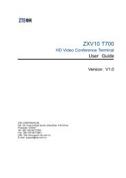
1Room IntegrationSetting Up a Room <strong>for</strong> Video ConferencingFor detailed in<strong>for</strong>mation about setting up a room <strong>for</strong> video conferencing, referto Room Design and Layout on page A-1.Room Layout ExamplesUse the following diagrams as examples <strong>for</strong> setting up a conference room with<strong>Polycom</strong>® <strong>HDX</strong> systems. <strong>Polycom</strong> recommends that you contract anexperienced contractor to assure all the components operate as a singlecohesive system.Small Conference RoomAcoustic PanelsDry Erase BoardVideoLight<strong>Polycom</strong> Eagle Eye onFlat Panel MonitorMedia Center withBuilt-In SpeakersVideoLight<strong>Polycom</strong>MicrophoneAcoustic QualityDrapes1 - 1
Integrator’s <strong>Reference</strong> <strong>Manual</strong> <strong>for</strong> <strong>Polycom</strong> <strong>HDX</strong> SystemsLarge Conference RoomAcoustic PanelsDocument Camera<strong>Polycom</strong>MicrophoneFlat PanelMonitor 1<strong>Polycom</strong> <strong>HDX</strong> systemand Eagle Eye cameraFlat PanelMonitor 2Media Center<strong>Network</strong> OutletsPower Outlets1 - 2
Room IntegrationClassroomTeacher’sPodiumTouch PanelComputerDocumentCameraMonitor 1<strong>Polycom</strong> Camera 2<strong>HDX</strong> systemwith EagleMonitor 2Eye cameraMonitor <strong>for</strong>and VortexVGA OutmixerTable-Top MicrophonesSetting Up the Room <strong>for</strong> People On ContentFor the best results, follow these guidelines <strong>for</strong> setting up People OnContent:• Use the <strong>Polycom</strong> Eagle Eye camera.• Create a flat, consistent background color using a screen or matte-finishpaint in green or blue. Make sure the background does not have shadowsor glare.1 - 3
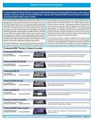
1212<strong>PC</strong> CARD100-240VAC 50/60Hz 4A<strong>PC</strong> CARD100-240VAC 50/60Hz 4ARoom IntegrationConnecting <strong>Polycom</strong> CamerasYou can connect <strong>Polycom</strong> <strong>HDX</strong> systems to a <strong>Polycom</strong> Eagle Eye, PowerCamor PowerCam Plus camera from <strong>Polycom</strong>, or to other supported cameras. Youmust use a PowerCam Plus as the main camera, not as a secondary camera.Refer to the release notes <strong>for</strong> a list of supported PTZ cameras.<strong>Polycom</strong> Eagle Eye as the Main CameraYou can connect a <strong>Polycom</strong> Eagle Eye camera (part number 8200-23600-001 or8200-23610-001) to a <strong>Polycom</strong> <strong>HDX</strong> system as the main camera using:• HDCI analog camera cable shown on page 2-1611<strong>Polycom</strong> Eagle Eye as the Second CameraYou can connect a <strong>Polycom</strong> Eagle Eye camera (part number 8200-23600-001 or8200-23610-001) to a <strong>Polycom</strong> <strong>HDX</strong> system as the second camera using:• HDCI analog camera cable shown on page 2-16• Power supply. Use only the approved power supply from <strong>Polycom</strong> (partnumber 1465-52621-036). Do not exceed 12 Volts at 3 Amps.22DC IN 12V1 - 5
Integrator’s <strong>Reference</strong> <strong>Manual</strong> <strong>for</strong> <strong>Polycom</strong> <strong>HDX</strong> SystemsPowerCam as the Main Camera up to 10 ft AwayYou can connect a PowerCam (part number 2215-50370-001) to a <strong>Polycom</strong> <strong>HDX</strong>system as the main camera up to 10 ft away using:• A—PowerCam Primary cable shown on page 2-24• B—HDCI PowerCam Plus adapter cable shown on page 2-21A11B1 - 6
Room IntegrationPowerCam as the Secondary CameraThe following kits are available, which include the power supply, PowerCamBreak-Out cable, PowerCam/VISCA Control cable, and S-Video cable:• 7230-22231-001 (50 ft)• 7230-22232-001 (100 ft)You can connect a PowerCam (part number 2215-50370-001) to a <strong>Polycom</strong> <strong>HDX</strong>system as the second camera using:• A—PowerCam Break-Out cable shown on page 2-25• B—PowerCam/VISCA Control cable shown on page 2-26• C—S-Video cable shown on page 2-9• D—HDCI PowerCam Plus adapter cable shown on page 2-21• Power Supply (part number 1465-52621-036)ABCD221 - 7
Integrator’s <strong>Reference</strong> <strong>Manual</strong> <strong>for</strong> <strong>Polycom</strong> <strong>HDX</strong> SystemsYou can connect a PowerCam (part number 2215-50370-001) to a <strong>Polycom</strong> <strong>HDX</strong>system as the third camera using:• A—PowerCam Break-Out cable shown on page 2-25• B—8-pin mini-DIN to DB-9 cable shown on page 2-27• C—S-Video cable shown on page 2-9• D—S-Video to BNC adapter shown on page 2-11• Power Supply (part number 1465-52621-036)ABCDIOIOIOYC3VCR/DVDIOIOIO3VCR/DVD1 - 8
Room IntegrationPowerCam Plus as the Main Camera up to 10’ AwayYou can connect a PowerCam Plus (part number 2215-50200-001) to a <strong>Polycom</strong><strong>HDX</strong> system as the main camera up to 10 ft away using:• A—PowerCam Plus Primary cable shown on page 2-20• B—HDCI PowerCam Plus adapter cable shown on page 2-21AB11<strong>Polycom</strong> <strong>HDX</strong> systems do not support automatic camera tracking with thePowerCam Plus camera.1 - 9
Integrator’s <strong>Reference</strong> <strong>Manual</strong> <strong>for</strong> <strong>Polycom</strong> <strong>HDX</strong> SystemsConnecting Other Video CamerasRefer to the release notes <strong>for</strong> a list of supported Pan/Tilt/Zoom (PTZ)cameras.To connect a PTZ camera to a <strong>Polycom</strong> <strong>HDX</strong> system as the main or secondcamera:You can connect a Sony or ELMO PTZ camera to a <strong>Polycom</strong> <strong>HDX</strong> systemusing:• HDCI Sony VISCA camera adaptor cable shown on page 2-23• S-Video cable• VISCA cableYou can connect a Vaddio or Canon (with VISCA cable shoe) PTZ camera to a<strong>Polycom</strong> <strong>HDX</strong> system using:• HDCI VISCA adaptor cable shown on page 2-221 - 10
Y12IOIOIO1C1Y221CY33 VCR/DVDVCR/DVDY43 VCR/DVDCC4143 VCR/DVD5IRLAN100-240VAC 50/60Hz 4A<strong>PC</strong> CARDRoom IntegrationIntegrating Audio<strong>Polycom</strong> strongly recommends using <strong>Polycom</strong> InstantDesigner to get started withyour <strong>Polycom</strong> Vortex® mixer integration. InstantDesigner resolves many commonissues with connections and configuration settings.To use a <strong>Polycom</strong> <strong>HDX</strong> system with audio input from a Vortex mixer, set the InputType to Line Input and disable Echo Canceller.Connecting a <strong>Polycom</strong> <strong>HDX</strong> System to a Vortex MixerConnect a <strong>Polycom</strong> <strong>HDX</strong> system to the Vortex mixer using:• Vortex cable shown on page 2-36ABABIOIOIO1 11 - 11
Integrator’s <strong>Reference</strong> <strong>Manual</strong> <strong>for</strong> <strong>Polycom</strong> <strong>HDX</strong> Systems1 - 12
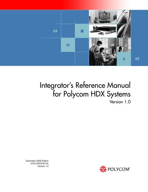
2CablesThis chapter includes in<strong>for</strong>mation about cables that can be used with a<strong>Polycom</strong> <strong>HDX</strong> system. Please note that drawings and part numbers areprovided <strong>for</strong> reference only. Compliance in<strong>for</strong>mation is provided <strong>for</strong> theRestriction of certain Hazardous Substances Directive (RoHS).<strong>Network</strong> CablesCAT 5e LAN CableThis cable connects a <strong>Polycom</strong> <strong>HDX</strong> system to the LAN. It has orange RJ-45connectors on both ends. It meets category 5e requirements and is wiredaccording to EIA/TIA-568B. The maximum approved length <strong>for</strong> this cable is100 ft (30 m) on an 802 network.Length Part Number RoHS Compliant12 ft (3.6 m) 2457-23537-001 YesT568B PairDrawings and part numbers are provided <strong>for</strong> reference only. <strong>Polycom</strong> claims no responsibilityor liability <strong>for</strong> the quality, per<strong>for</strong>mance, or reliability of cables based on these referencedrawings, other than cables provided by <strong>Polycom</strong>. Contact your <strong>Polycom</strong> distributor or<strong>Polycom</strong> Custom/Vertical Products to order cables that meet the appropriate manufacturingtolerances, quality, and per<strong>for</strong>mance parameters <strong>for</strong> your application.2 - 1
Integrator’s <strong>Reference</strong> <strong>Manual</strong> <strong>for</strong> <strong>Polycom</strong> <strong>HDX</strong> SystemsISDN CableThis cable connects a <strong>Polycom</strong> <strong>HDX</strong> system to a BRI or PRI line. It has clearRJ-45 connectors on both ends and is used with all <strong>Polycom</strong> <strong>HDX</strong> systems thathave ISDN capability. The maximum approved length <strong>for</strong> this cable is 50 ft(15 m).Length Part Number RoHS Compliant20 ft (6.6 m) 2457-08548-001 YesDrawings and part numbers are provided <strong>for</strong> reference only. <strong>Polycom</strong> claims no responsibilityor liability <strong>for</strong> the quality, per<strong>for</strong>mance, or reliability of cables based on these referencedrawings, other than cables provided by <strong>Polycom</strong>. Contact your <strong>Polycom</strong> distributor or<strong>Polycom</strong> Custom/Vertical Products to order cables that meet the appropriate manufacturingtolerances, quality, and per<strong>for</strong>mance parameters <strong>for</strong> your application.PRI Pin AssignmentsThe following illustration and table show the pin assignments <strong>for</strong> the PRI porton the <strong>Polycom</strong> <strong>HDX</strong> system.Pin 8Pin 1Pin12345678Signal NameReceive RingReceive TipNo ConnectionTransmit RingTransmit TipNo ConnectionNo ConnectionNo Connection2 - 2
CablesAnalog Telephone (POTS) CableThis cable connects a <strong>Polycom</strong> <strong>HDX</strong> system to an analog telephone line. It haspink RJ-11 connectors on both ends. The maximum approved length <strong>for</strong> thiscable is 100 ft (30 m).Length Part Number RoHS Compliant12 ft (3.6 m) 2457-20071-001 YesDrawings and part numbers are provided <strong>for</strong> reference only. <strong>Polycom</strong> claims no responsibilityor liability <strong>for</strong> the quality, per<strong>for</strong>mance, or reliability of cables based on these referencedrawings, other than cables provided by <strong>Polycom</strong>. Contact your <strong>Polycom</strong> distributor or<strong>Polycom</strong> Custom/Vertical Products to order cables that meet the appropriate manufacturingtolerances, quality, and per<strong>for</strong>mance parameters <strong>for</strong> your application.2 - 3
Integrator’s <strong>Reference</strong> <strong>Manual</strong> <strong>for</strong> <strong>Polycom</strong> <strong>HDX</strong> SystemsV.35/RS-449/RS-530 Serial AdapterThis adapter is used when connecting a <strong>Polycom</strong> <strong>HDX</strong> system to otherthird-party network equipment. It adapts the 68-pin interface to an industrystandard 44-pin interface used by some network interface equipment. It isused with <strong>Polycom</strong> <strong>HDX</strong> systems that have a V.35/RS-449/RS-530 serialnetwork interface card (NIC) installed.Length Part Number RoHS Compliant6 in (15.23 cm) 2457-21264-200 YesPeripheral LinkV.35 HD-68 PinoutNotes (direction from V.35 module (DTE))68 pin Signal Name Signal Type From card Function V.35 RS530-DB25 RS4449-DB37 RS366-DB25Shield V.35/RS449/RS530 A 19 7,18,19#12 Receive Data A Differential in V.35/RS449/RS530 R 3 611 Receive Data B Differential in V.35/RS449/RS530 T 16 2410 Send Timing A Differential in V.35/RS449/RS530 Y 15 59 Send Timing B Differential in V.35/RS449/RS530 AA 12 2329 Data Set Ready (DSR) Single Ended in V.35 E28 Request To Send (RTS) Single Ended out V.35 C27 Data Terminal Ready (DTR) Single Ended out V.35 H34 Digit Present (DPR) Single Ended out RS366 224 Abandon Call/Retry (ACR) Single Ended in RS366 332 Call Request (CRQ) Single Ended out RS366 426 Present Next Digit (PND) Single Ended in RS366 521 Data Line Occupied (DLO) Single Ended in RS366 2214 Receive Timing A Differential in V.35/RS449/RS530 V 17 813 Receive Timing B Differential in V.35/RS449/RS530 X 9 268 Terminal Timing A Differential out V.35/RS449/RS530 U 24 177 Terminal Timing B Differential out V.35/RS449/RS530 W 11 3515 Request To Send (RTS) A Differential out RS449/RS530 4 716 Request To Send (RTS) B Differential out RS449/RS530 19 2535** Receive Common Gnd RS449 2020 BCD Dial Digit Bit 1 (NB1) Single Ended out RS366 1419 BCD Dial Digit Bit 2 (NB2) Single Ended out RS366 1523 BCD Dial Digit Bit 4 (NB4) Single Ended out RS366 1625 BCD Dial Digit Bit 8 (NB8) Single Ended out RS366 172** Signal Ground Gnd V.35/RS366 B 7,18,196 Send Data A Differential out V.35/RS449/RS530 P 2 45 Send Data B Differential out V.35/RS449/RS530 S 14 22reserved (Ascend select line)63 Clear To Send (CTS) A Differential in RS449/RS530 5 964 Clear To Send (CTS) B Differential in RS449/RS530 13 2761 Data Mode (DM-DSR) A Differential in RS449/RS530 6 1162 Data Mode (DM-DSR) B Differential in RS449/RS530 22 2965 Receiver Ready (RR-DCD) A Differential in RS449/RS530 8 1366 Receiver Ready (RR-DCD) B Differential in RS449/RS530 10 314** Send Common Gnd RS530 7 3733 Data Carrier Detect (DCD) Single Ended in V.35 F18 Terminal Ready (TR-DTR) A Differential out RS449/RS530 20 1217 Terminal Ready (TR-DTR) B Differential out RS449/RS530 23 303 V.35 Cable Connected ground to indicate a V.35 cable is attached 7,18,19*1 RS449 Cable Connected ground to indicate a RS449 cable is attached 7,18,19^#22 Distant Station Connected (DSC) Single Ended in RS366 1330 Clear To Send (CTS) Single Ended in V.35 D31 Ring Indicate (RI) (<strong>Inc</strong>oming Call)Single Ended in V.35/RS449 J 15reserved (Ascend select line)68 LOS A Differential out RS530 crypto 18 367 LOS B Differential out RS530 crypto 21 21* For V.35, connect pin 3 of 68 pin connector to ground^For RS449, connect pin 1 of 68 pin connector to ground#For RS530, connect pins 1 and 3 of 68 pin connector to ground** Gnd pins are 2,4, 35-60Drawings and part numbers are provided <strong>for</strong> reference only. <strong>Polycom</strong> claims no responsibilityor liability <strong>for</strong> the quality, per<strong>for</strong>mance, or reliability of cables based on these referencedrawings, other than cables provided by <strong>Polycom</strong>. Contact your <strong>Polycom</strong> distributor or<strong>Polycom</strong> Custom/Vertical Products to order cables that meet the appropriate manufacturingtolerances, quality, and per<strong>for</strong>mance parameters <strong>for</strong> your application.2 - 4
CablesV.35 NIC CableThis cable connects a <strong>Polycom</strong> <strong>HDX</strong> system to Ascend network equipment. Itis used with the V.35/RS-449/RS-530 serial adapter on page 2-4 to connect tonetwork equipment that has the HD-44 pin interface. It has HD-44 Mconnectors on both ends and is used with <strong>Polycom</strong> <strong>HDX</strong> systems that have aserial network interface card (NIC) installed.Length Part Number RoHS Compliant5 ft (1.65 m) 2457-10608-001 —Drawings and part numbers are provided <strong>for</strong> reference only. <strong>Polycom</strong> claims no responsibilityor liability <strong>for</strong> the quality, per<strong>for</strong>mance, or reliability of cables based on these referencedrawings, other than cables provided by <strong>Polycom</strong>. Contact your <strong>Polycom</strong> distributor or<strong>Polycom</strong> Custom/Vertical Products to order cables that meet the appropriate manufacturingtolerances, quality, and per<strong>for</strong>mance parameters <strong>for</strong> your application.2 - 5
Integrator’s <strong>Reference</strong> <strong>Manual</strong> <strong>for</strong> <strong>Polycom</strong> <strong>HDX</strong> SystemsV.35 and RS-366 Serial CableThis cable connects a <strong>Polycom</strong> <strong>HDX</strong> system to third-party network equipment.It is used with the V.35/RS-449/RS-530 serial adapter on page 2-4 to connectto network equipment that has a V.35/RS-366 interface. It is HD-44 M to “Y”Winchester 34M/RS-366 DB-25M and is used with <strong>Polycom</strong> <strong>HDX</strong> systems thathave a serial network interface card (NIC) installed.Length Part Number RoHS Compliant5 ft (1.65 m) 2457-10609-001 —Drawings and part numbers are provided <strong>for</strong> reference only. <strong>Polycom</strong> claims no responsibilityor liability <strong>for</strong> the quality, per<strong>for</strong>mance, or reliability of cables based on these referencedrawings, other than cables provided by <strong>Polycom</strong>. Contact your <strong>Polycom</strong> distributor or<strong>Polycom</strong> Custom/Vertical Products to order cables that meet the appropriate manufacturingtolerances, quality, and per<strong>for</strong>mance parameters <strong>for</strong> your application.2 - 6
CablesRS-449 and RS-366 Serial CableThis cable connects a <strong>Polycom</strong> <strong>HDX</strong> system to third-party network equipment.It is used with the V.35/RS-449/RS-530 serial adapter on page 2-4 to connectto network equipment that has an RS-449/RS-366 interface. It is HD-44 M to“Y” RS-449 DB-37M/RS-366 DB-25M and is used with <strong>Polycom</strong> <strong>HDX</strong> systemsthat have a serial network interface card (NIC) installed.Length Part Number RoHS Compliant5 ft (1.65 m) 2457-10610-001 —Drawings and part numbers are provided <strong>for</strong> reference only. <strong>Polycom</strong> claims no responsibilityor liability <strong>for</strong> the quality, per<strong>for</strong>mance, or reliability of cables based on these referencedrawings, other than cables provided by <strong>Polycom</strong>. Contact your <strong>Polycom</strong> distributor or<strong>Polycom</strong> Custom/Vertical Products to order cables that meet the appropriate manufacturingtolerances, quality, and per<strong>for</strong>mance parameters <strong>for</strong> your application.2 - 7
Integrator’s <strong>Reference</strong> <strong>Manual</strong> <strong>for</strong> <strong>Polycom</strong> <strong>HDX</strong> SystemsRS-530 with RS-366 Serial CableThis cable connects a <strong>Polycom</strong> <strong>HDX</strong> system to third-party network equipment.It is used with the V.35/RS-449/RS-530 serial adapter on page 2-4 to connectto network equipment that has an RS-530/RS-366 interface. It is HD-68M to“Y” DB-25M and is used with <strong>Polycom</strong> <strong>HDX</strong> systems that have a serialnetwork interface card (NIC) installed.Length Part Number RoHS Compliant5 ft (1.65 m) 2457-21263-001 YesPeripheral Link V.35 HD-68 PinoutNotes (direction from V.35 module (DTE))68 pin Signal Name Signal Type From card Function RS530-DB25 RS366-DB25Shield V.35/RS449/RS530 7,18,19#12 Receive Data A Differential in V.35/RS449/RS530 311 Receive Data B Differential in V.35/RS449/RS530 1610 Send Timing A Differential in V.35/RS449/RS530 159 Send Timing B Differential in V.35/RS449/RS530 1229 Data Set Ready (DSR) Single Ended in V.3528 Request To Send (RTS) Single Ended out V.3527 Data Terminal Ready (DTR) Single Ended out V.3534 Digit Present (DPR) Single Ended out RS366 224 Abandon Call/Retry (ACR) Single Ended in RS366 332 Call Request (CRQ) Single Ended out RS366 426 Present Next Digit (PND) Single Ended in RS366 521 Data Line Occupied (DLO) Single Ended in RS366 2214 Receive Timing A Differential in V.35/RS449/RS530 1713 Receive Timing B Differential in V.35/RS449/RS530 98 Terminal Timing A Differential out V.35/RS449/RS530 247 Terminal Timing B Differential out V.35/RS449/RS530 1115 Request To Send (RTS) A Differential out RS449/RS530 416 Request To Send (RTS) B Differential out RS449/RS530 1935** Receive Common Gnd RS44920 BCD Dial Digit Bit 1 (NB1) Single Ended out RS366 1419 BCD Dial Digit Bit 2 (NB2) Single Ended out RS366 1523 BCD Dial Digit Bit 4 (NB4) Single Ended out RS366 1625 BCD Dial Digit Bit 8 (NB8) Single Ended out RS366 172** Signal Ground Gnd V.35/RS366 7,18,196 Send Data A Differential out V.35/RS449/RS530 25 Send Data B Differential out V.35/RS449/RS530 14reserved (Ascend select line)63 Clear To Send (CTS) A Differential in RS449/RS530 564 Clear To Send (CTS) B Differential in RS449/RS530 1361 Data Mode (DM-DSR) A Differential in RS449/RS530 662 Data Mode (DM-DSR) B Differential in RS449/RS530 2265 Receiver Ready (RR-DCD) A Differential in RS449/RS530 866 Receiver Ready (RR-DCD) B Differential in RS449/RS530 104** Send Common Gnd RS530 733 Data Carrier Detect (DCD) Single Ended in V.3518 Terminal Ready (TR-DTR) A Differential out RS449/RS530 2017 Terminal Ready (TR-DTR) B Differential out RS449/RS530 233 V.35 Cable Connected ground to indicate a V.35 cable is attached 7,18,19*1 RS449 Cable Connected ground to indicate a RS449 cable is attached 7,18,19^#22 Distant Station Connected (DSC) Single Ended in RS366 1330 Clear To Send (CTS) Single Ended in V.3531 Ring Indicate (RI) (<strong>Inc</strong>oming Call)Single Ended in V.35/RS449reserved (Ascend select line)68 LOS A Differential out RS530 crypto 1867 LOS B Differential out RS530 crypto 21* For V.35, connect pin 3 of 68 pin connector to ground^For RS449, connect pin 1 of 68 pin connector to ground#For RS530, connect pins 1 and 3 of 68 pin connector to ground** Gnd pins are 2,4, 35-60Drawings and part numbers are provided <strong>for</strong> reference only. <strong>Polycom</strong> claims no responsibilityor liability <strong>for</strong> the quality, per<strong>for</strong>mance, or reliability of cables based on these referencedrawings, other than cables provided by <strong>Polycom</strong>. Contact your <strong>Polycom</strong> distributor or<strong>Polycom</strong> Custom/Vertical Products to order cables that meet the appropriate manufacturingtolerances, quality, and per<strong>for</strong>mance parameters <strong>for</strong> your application.2 - 8
CablesVideo and Camera CablesS-Video CableThese cables connect a <strong>Polycom</strong> <strong>HDX</strong> system to a monitor or camera. Theyhave yellow 4-pin mini-DIN connectors on both ends and are used with all<strong>Polycom</strong> <strong>HDX</strong> systems. The maximum approved length <strong>for</strong> this cable is 200 ft(60 m).Length Part Number RoHS Compliant25 ft (7.6 m) 2457-08409-002 Yes8 ft (2.4 m) 2457-08410-002 Yes50 ft (15 m) 2457-09204-200 YesMINI-DIN MALE 4 POS. ( x2 )25 FEET +/- 2"P3P4P3P4P1P2P1P2Drawings and part numbers are provided <strong>for</strong> reference only. <strong>Polycom</strong> claims no responsibilityor liability <strong>for</strong> the quality, per<strong>for</strong>mance, or reliability of cables based on these referencedrawings, other than cables provided by <strong>Polycom</strong>. Contact your <strong>Polycom</strong> distributor or<strong>Polycom</strong> Custom/Vertical Products to order cables that meet the appropriate manufacturingtolerances, quality, and per<strong>for</strong>mance parameters <strong>for</strong> your application.2 - 9
Integrator’s <strong>Reference</strong> <strong>Manual</strong> <strong>for</strong> <strong>Polycom</strong> <strong>HDX</strong> SystemsBNC to S-Video CableThis cable connects S-Video devices to a <strong>Polycom</strong> <strong>HDX</strong> system. It is 4-pin malemini-DIN to dual BNC. The maximum approved length <strong>for</strong> this cable is 100 ft(30 m).Length Part Number RoHS Compliant6 ft (1.8 m) 2457-21489-200 YesDimensions are in millimetersDrawings and part numbers are provided <strong>for</strong> reference only. <strong>Polycom</strong> claims no responsibilityor liability <strong>for</strong> the quality, per<strong>for</strong>mance, or reliability of cables based on these referencedrawings, other than cables provided by <strong>Polycom</strong>. Contact your <strong>Polycom</strong> distributor or<strong>Polycom</strong> Custom/Vertical Products to order cables that meet the appropriate manufacturingtolerances, quality, and per<strong>for</strong>mance parameters <strong>for</strong> your application.2 - 10
CablesBNC to S-Video AdapterThis adapter may be required when connecting standard S-Video cables to a<strong>Polycom</strong> <strong>HDX</strong> system. It is dual BNC to 4-pin female mini-DIN.Length Part Number RoHS Compliant1 ft (.3 m) 2457-21490-200 YesDimensions are in millimetersDrawings and part numbers are provided <strong>for</strong> reference only. <strong>Polycom</strong> claims no responsibilityor liability <strong>for</strong> the quality, per<strong>for</strong>mance, or reliability of cables based on these referencedrawings, other than cables provided by <strong>Polycom</strong>. Contact your <strong>Polycom</strong> distributor or<strong>Polycom</strong> Custom/Vertical Products to order cables that meet the appropriate manufacturingtolerances, quality, and per<strong>for</strong>mance parameters <strong>for</strong> your application.2 - 11
Integrator’s <strong>Reference</strong> <strong>Manual</strong> <strong>for</strong> <strong>Polycom</strong> <strong>HDX</strong> SystemsDVI to VGA Monitor CableThis cable connects a <strong>Polycom</strong> <strong>HDX</strong> system DVI-I output to a VGA monitor. Itcan also be used to connect a computer to one of the DVI-I video inputs on a<strong>Polycom</strong> <strong>HDX</strong> system. It is male DVI-A to male HD-15.Length Part Number RoHS Compliant9 ft 10 in (3 m) 2457-23792-001 YesDrawings and part numbers are provided <strong>for</strong> reference only. <strong>Polycom</strong> claims no responsibilityor liability <strong>for</strong> the quality, per<strong>for</strong>mance, or reliability of cables based on these referencedrawings, other than cables provided by <strong>Polycom</strong>. Contact your <strong>Polycom</strong> distributor or<strong>Polycom</strong> Custom/Vertical Products to order cables that meet the appropriate manufacturingtolerances, quality, and per<strong>for</strong>mance parameters <strong>for</strong> your application.2 - 12
CablesHDMI Monitor CableThis cable connects the <strong>Polycom</strong> <strong>HDX</strong> system DVI-I output to an HDMImonitor. It is male DVI-D to male HDMI.Length Part Number RoHS Compliant9 ft 10 in (3 m) 2457-23905-001 YesDrawings and part numbers are provided <strong>for</strong> reference only. <strong>Polycom</strong> claims no responsibilityor liability <strong>for</strong> the quality, per<strong>for</strong>mance, or reliability of cables based on these referencedrawings, other than cables provided by <strong>Polycom</strong>. Contact your <strong>Polycom</strong> distributor or<strong>Polycom</strong> Custom/Vertical Products to order cables that meet the appropriate manufacturingtolerances, quality, and per<strong>for</strong>mance parameters <strong>for</strong> your application.2 - 13
Integrator’s <strong>Reference</strong> <strong>Manual</strong> <strong>for</strong> <strong>Polycom</strong> <strong>HDX</strong> SystemsBNC Monitor Adapter CableThis cable connects the <strong>Polycom</strong> <strong>HDX</strong> system DVI-I output to a variety ofanalog display devices with composite, S-Video, component YPbPr, orRGBHV inputs. It is male DVI-A to five female BNC connectors.Length Part Number RoHS Compliant1 ft (0.3 m) 2457-23533-001 YesDrawings and part numbers are provided <strong>for</strong> reference only. <strong>Polycom</strong> claims no responsibilityor liability <strong>for</strong> the quality, per<strong>for</strong>mance, or reliability of cables based on these referencedrawings, other than cables provided by <strong>Polycom</strong>. Contact your <strong>Polycom</strong> distributor or<strong>Polycom</strong> Custom/Vertical Products to order cables that meet the appropriate manufacturingtolerances, quality, and per<strong>for</strong>mance parameters <strong>for</strong> your application.2 - 14
CablesDVI-D Monitor CableThis cable connects a <strong>Polycom</strong> <strong>HDX</strong> system DVI-I output to a DVI-D monitor.It is male DVI-D on both ends.Length Part Number RoHS Compliant9 ft 10 in (3 m) 2457-23793-001 YesDrawings and part numbers are provided <strong>for</strong> reference only. <strong>Polycom</strong> claims no responsibilityor liability <strong>for</strong> the quality, per<strong>for</strong>mance, or reliability of cables based on these referencedrawings, other than cables provided by <strong>Polycom</strong>. Contact your <strong>Polycom</strong> distributor or<strong>Polycom</strong> Custom/Vertical Products to order cables that meet the appropriate manufacturingtolerances, quality, and per<strong>for</strong>mance parameters <strong>for</strong> your application.2 - 15
Integrator’s <strong>Reference</strong> <strong>Manual</strong> <strong>for</strong> <strong>Polycom</strong> <strong>HDX</strong> SystemsHDCI Analog Camera CableThis cable connects a <strong>Polycom</strong> <strong>HDX</strong> system to a <strong>Polycom</strong> Eagle Eye camera. Ithas male HDCI connectors on both ends.Length Part Number RoHS Compliant9 ft 10 in (3 m) 2457-23180-003 Yes33 ft (10 m) 2457-23180-010 YesDrawings and part numbers are provided <strong>for</strong> reference only. <strong>Polycom</strong> claims no responsibilityor liability <strong>for</strong> the quality, per<strong>for</strong>mance, or reliability of cables based on these referencedrawings, other than cables provided by <strong>Polycom</strong>. Contact your <strong>Polycom</strong> distributor or<strong>Polycom</strong> Custom/Vertical Products to order cables that meet the appropriate manufacturingtolerances, quality, and per<strong>for</strong>mance parameters <strong>for</strong> your application.2 - 16
CablesHDCI Camera Break-Out CableThis cable breaks out the HDCI camera cable video and control signals tostandard interfaces. The five BNC connectors can be used to carry compositevideo, S-Video, or analog component YPbPr video. The DB-9 connector is usedto connect to PTZ camera control interfaces. It is male HDCI to five femaleBNC and one female DB-9.Length Part Number RoHS Compliant1ft (0.3 m) 2457-23521-001 YesDrawings and part numbers are provided <strong>for</strong> reference only. <strong>Polycom</strong> claims no responsibilityor liability <strong>for</strong> the quality, per<strong>for</strong>mance, or reliability of cables based on these referencedrawings, other than cables provided by <strong>Polycom</strong>. Contact your <strong>Polycom</strong> distributor or<strong>Polycom</strong> Custom/Vertical Products to order cables that meet the appropriate manufacturingtolerances, quality, and per<strong>for</strong>mance parameters <strong>for</strong> your application.2 - 17
Integrator’s <strong>Reference</strong> <strong>Manual</strong> <strong>for</strong> <strong>Polycom</strong> <strong>HDX</strong> SystemsVCR/DVD Composite CableThis cable connects a <strong>Polycom</strong> <strong>HDX</strong> system to a VCR or DVD player. It hastriple RCA connectors on both ends. The <strong>Polycom</strong> <strong>HDX</strong> system requires afemale RCA to male BNC adapter <strong>for</strong> the yellow video RCA connector, and theAudio Adapter Cable on page 2-34. The maximum approved length <strong>for</strong> thiscable is 50 ft (15 m).Length Part Number RoHS Compliant8 ft (2.6 m) 2457-08412-001 —Drawings and part numbers are provided <strong>for</strong> reference only. <strong>Polycom</strong> claims no responsibilityor liability <strong>for</strong> the quality, per<strong>for</strong>mance, or reliability of cables based on these referencedrawings, other than cables provided by <strong>Polycom</strong>. Contact your <strong>Polycom</strong> distributor or<strong>Polycom</strong> Custom/Vertical Products to order cables that meet the appropriate manufacturingtolerances, quality, and per<strong>for</strong>mance parameters <strong>for</strong> your application.2 - 18
CablesComposite Video CableThis cable connects a <strong>Polycom</strong> <strong>HDX</strong> system to a monitor or camera. It hassingle yellow RCA connectors on both ends. The <strong>Polycom</strong> <strong>HDX</strong> systemrequires a female RCA to male BNC adapter in order to connect to compositeinput or output. The maximum approved length <strong>for</strong> this cable is 100 ft (30 m).Length Part Number RoHS Compliant25 ft (7.6 m) 2457-09207-001 —Drawings and part numbers are provided <strong>for</strong> reference only. <strong>Polycom</strong> claims no responsibilityor liability <strong>for</strong> the quality, per<strong>for</strong>mance, or reliability of cables based on these referencedrawings, other than cables provided by <strong>Polycom</strong>. Contact your <strong>Polycom</strong> distributor or<strong>Polycom</strong> Custom/Vertical Products to order cables that meet the appropriate manufacturingtolerances, quality, and per<strong>for</strong>mance parameters <strong>for</strong> your application.2 - 19
Integrator’s <strong>Reference</strong> <strong>Manual</strong> <strong>for</strong> <strong>Polycom</strong> <strong>HDX</strong> SystemsPowerCam Plus Primary CableThis cable connects a <strong>Polycom</strong> <strong>HDX</strong> system to a <strong>Polycom</strong> PowerCam Pluscamera using the HDCI PowerCam Plus adapter cable on 2-21. It has 4-pinmini-DIN and DB-15 connectors on both ends.Length Part Number RoHS Compliant9 ft 10 in (3 m) 1457-50105-002 Yes30 ft (9 m) 1457-50105-230 Yes50 ft (15 m) 1457-50105-250 Yes100 ft (30 m) 1457-50105-300 Yes200mm / 7.87"200mm / 7.87"P1P3P2P440mm / 1.57"40mm / 1.57"4 61 5 72 3 810 129 11 13 14 15Front Viewof Connector13 423 Meters / 9' 10"P1 ConnectorP2 ConnectorPin # Signal Name Pin # Signal Name1 Arm Mic 1 Arm Mic2 Left Mic 2 Left Mic3 A GND 3 A GND4 Cam ID Bit 4 Cam ID Bit5 P GND 5 P GND6 +12V 6 +12V7 SW-RX/SN-TX 7 SW-RX/SN-TX8 IR signal 8 IR signal9 Center Mic 9 Center Mic10 Right Mic 10 Right Mic11 A GND 11 A GND12 P GND 12 P GND13 +12V 13 +12V14 SW-TX/SN-RX 14 SW-TX/SN-RX15 IR return 15 IR returnP3 4 Pin mini Din P4 4 Pin mini Din1 A GND 1 A GND2 A GND 2 A GND3 Luma 3 Luma4 Chroma 4 Chroma4 61 5 72 3 810 129 11 13 14 15Front Viewof Connector13 42Drawings and part numbers are provided <strong>for</strong> reference only. <strong>Polycom</strong> claims no responsibilityor liability <strong>for</strong> the quality, per<strong>for</strong>mance, or reliability of cables based on these referencedrawings, other than cables provided by <strong>Polycom</strong>. Contact your <strong>Polycom</strong> distributor or<strong>Polycom</strong> Custom/Vertical Products to order cables that meet the appropriate manufacturingtolerances, quality, and per<strong>for</strong>mance parameters <strong>for</strong> your application.2 - 20
CablesHDCI PowerCam Plus Adapter CableThis cable adapts a PowerCam Plus cable to HDCI. It is HDCI to 4-pinmini-DIN and DB-15. It can also be used with the PowerCam Primary cable(1457-50338-001) on page 2-24 to connect PowerCam.Length Part Number RoHS Compliant1 ft (0.3 m) 2457-23481-001 YesDrawings and part numbers are provided <strong>for</strong> reference only. <strong>Polycom</strong> claims no responsibilityor liability <strong>for</strong> the quality, per<strong>for</strong>mance, or reliability of cables based on these referencedrawings, other than cables provided by <strong>Polycom</strong>. Contact your <strong>Polycom</strong> distributor or<strong>Polycom</strong> Custom/Vertical Products to order cables that meet the appropriate manufacturingtolerances, quality, and per<strong>for</strong>mance parameters <strong>for</strong> your application.2 - 21
Integrator’s <strong>Reference</strong> <strong>Manual</strong> <strong>for</strong> <strong>Polycom</strong> <strong>HDX</strong> SystemsHDCI VISCA Adapter CableThis cable connects a <strong>Polycom</strong> <strong>HDX</strong> system HDCI video input to SD cameraswith VISCA control. It is HDCI to 4-pin mini-DIN and DB-9. Standard S-Videoand DB-9 serial cables are required to connect this cable to the camera.Length Part Number RoHS Compliant1 ft (0.3 m) 2457-23486-001 YesDrawings and part numbers are provided <strong>for</strong> reference only. <strong>Polycom</strong> claims no responsibilityor liability <strong>for</strong> the quality, per<strong>for</strong>mance, or reliability of cables based on these referencedrawings, other than cables provided by <strong>Polycom</strong>. Contact your <strong>Polycom</strong> distributor or<strong>Polycom</strong> Custom/Vertical Products to order cables that meet the appropriate manufacturingtolerances, quality, and per<strong>for</strong>mance parameters <strong>for</strong> your application.2 - 22
CablesHDCI Sony VISCA Adapter CableThis cable connects a <strong>Polycom</strong> <strong>HDX</strong> system HDCI video input to a camerausing Sony 8-pin mini DIN VISCA and S-Video. It is HDCI to 8-pin mini-DINand S-Video. Standard S-Video and Sony VISCA cables are required to connectthis cable to the camera.Length Part Number RoHS Compliant1 ft (0.3 m) 2457-23549-001 YesDrawings and part numbers are provided <strong>for</strong> reference only. <strong>Polycom</strong> claims no responsibilityor liability <strong>for</strong> the quality, per<strong>for</strong>mance, or reliability of cables based on these referencedrawings, other than cables provided by <strong>Polycom</strong>. Contact your <strong>Polycom</strong> distributor or<strong>Polycom</strong> Custom/Vertical Products to order cables that meet the appropriate manufacturingtolerances, quality, and per<strong>for</strong>mance parameters <strong>for</strong> your application.2 - 23
Integrator’s <strong>Reference</strong> <strong>Manual</strong> <strong>for</strong> <strong>Polycom</strong> <strong>HDX</strong> SystemsPowerCam Primary Camera CableThis cable connects the <strong>Polycom</strong> <strong>HDX</strong> system video input 1 to a <strong>Polycom</strong>PowerCam camera up to 10 ft away when used with the HDCI PowerCamPlus Adapter cable on page 2-21. It is 8-pin mini-DIN to 4-pin mini-DIN andDB-15. The maximum approved length <strong>for</strong> this cable is 10 ft (3 m).Length Part Number RoHS Compliant9 ft 10 in (3 m) 1457-50338-002 Yes200mm / 7.87"123 44Pin Mini DinMaleP31 2 3 4 5 6 7 89 10 11 12 13 14 1540mm(1.57")P1Molded PVC strain relief4-40 Jack screw3 Meters +/- 50.80mmPan Int'l 73069-008-T068 Pin Mini DinMaleP256 7 8341 215 Pin D-subMaleP1 15 Pin D ConnectorP2 8 Pin mini DinPin # Signal Name Wire Type Pin # Signal Name1-4 N/C5 PGND 22AWG wire 3 DGND6 +12V 22 AWG wire 7 +12V7 SW-RX/SN-TX 30 AWG wire 2 SW-RX/SN-TX8 IR-SIGNAL 30 AWG wire 4 IR_SIGNAL9-11 N/C12 P GND 22 AWG wire 3 DGND13 +12V 22 AWG wire 7 +12V14 SW-TX/SN-RX 30 AWG wire 1 SW-TX/SN-RX15 IR RETURN 30 AWG wire 3 DGNDSHIELD DRAIN wire SHIELDP3 4 Pin Mini Din1 RTN Coax Shield 5 GVID2 RTN Coax Shield 5 GVID3 Luma Micro Coax 6 Luma4 Chro ma Micro Coax 8 ChromaSHIELD DRAIN wire SHIELDDrawings and part numbers are provided <strong>for</strong> reference only. <strong>Polycom</strong> claims no responsibilityor liability <strong>for</strong> the quality, per<strong>for</strong>mance, or reliability of cables based on these referencedrawings, other than cables provided by <strong>Polycom</strong>. Contact your <strong>Polycom</strong> distributor or<strong>Polycom</strong> Custom/Vertical Products to order cables that meet the appropriate manufacturingtolerances, quality, and per<strong>for</strong>mance parameters <strong>for</strong> your application.2 - 24
CablesPowerCam Break-Out CableThis cable connects S-Video and control cables and a power supply to a<strong>Polycom</strong> PowerCam camera. This combination is required when using thePowerCam as the primary camera more than 10 ft away from the system, or asthe secondary camera. It is 8-pin mini-DIN to 3-way breakout block.A separate power supply is required (part number 1465-52621-036).Length Part Number RoHS Compliant6 ft (1.8 m) 2457-50526-200 YesMolded PVC strain reliefP28 7 65 4 32 14231J28 PinMini DinFemaleP1DCJackJ14 PinMini DinFemale6' ± 2.0"8 Pin Mini DinMaleDrawings and part numbers are provided <strong>for</strong> reference only. <strong>Polycom</strong> claims no responsibilityor liability <strong>for</strong> the quality, per<strong>for</strong>mance, or reliability of cables based on these referencedrawings, other than cables provided by <strong>Polycom</strong>. Contact your <strong>Polycom</strong> distributor or<strong>Polycom</strong> Custom/Vertical Products to order cables that meet the appropriate manufacturingtolerances, quality, and per<strong>for</strong>mance parameters <strong>for</strong> your application.2 - 25
Integrator’s <strong>Reference</strong> <strong>Manual</strong> <strong>for</strong> <strong>Polycom</strong> <strong>HDX</strong> SystemsPowerCam Plus/VISCA Control Cable8-pin mini-DIN to DB-15This cable adapts the 8-pin mini-DIN VISCA control interface to thePowerCam Plus DB-15 control interface. It is used with the PowerCamBreak-Out cable and the HDCI PowerCam Plus adapter cable. It is 8-pinmini-DIN to DB-15.Length Part Number RoHS Compliant50 ft (15 m) 1457-50527-201 Yes1 2 3 4 5 6 7 89 10 11 12 13 14 15P150' ± 3.0"P28 Pin Mini DinMale56 7 8341 215 Pin D-subMaleP1 15 Pin D ConnectorP2 VISCA 8 Pin mini DinPin # Signal Name Pin # Signal Name1-6, 9-11, 13 NC 1, 2, 8 NC7 SW-RX/SN-TX 3 SW-RX/SN-TX8 IR-SIGNAL 7 IR OUT12 P GND 4 GND14 SW-TX/SN-RX 5 SW-TX/SN-RX15 IR RETURN 6 GNDSHIELDSHIELDDrawings and part numbers are provided <strong>for</strong> reference only. <strong>Polycom</strong> claims no responsibilityor liability <strong>for</strong> the quality, per<strong>for</strong>mance, or reliability of cables based on these referencedrawings, other than cables provided by <strong>Polycom</strong>. Contact your <strong>Polycom</strong> distributor or<strong>Polycom</strong> Custom/Vertical Products to order cables that meet the appropriate manufacturingtolerances, quality, and per<strong>for</strong>mance parameters <strong>for</strong> your application.2 - 26
Cables8-pin mini-DIN to DB-9This cable connects <strong>Polycom</strong> <strong>HDX</strong> system serial port inputs to a non-<strong>Polycom</strong>camera using a VISCA 8-pin DIN connector, or to a <strong>Polycom</strong> PowerCambreak-out cable with a PowerCam camera. It is 8-pin mini-DIN to DB-9.RTS/CTS and IR are not supported on this cable.Length Part Number RoHS Compliant50 ft (15 m) 2457-10029-200 Yes100 ft (30 m) 2457-21259-001 —Drawings and part numbers are provided <strong>for</strong> reference only. <strong>Polycom</strong> claims no responsibilityor liability <strong>for</strong> the quality, per<strong>for</strong>mance, or reliability of cables based on these referencedrawings, other than cables provided by <strong>Polycom</strong>. Contact your <strong>Polycom</strong> distributor or<strong>Polycom</strong> Custom/Vertical Products to order cables that meet the appropriate manufacturingtolerances, quality, and per<strong>for</strong>mance parameters <strong>for</strong> your application.2 - 27
Integrator’s <strong>Reference</strong> <strong>Manual</strong> <strong>for</strong> <strong>Polycom</strong> <strong>HDX</strong> SystemsPowerCam/VISCA Control CableThis cable connects a <strong>Polycom</strong> <strong>HDX</strong> system to a camera VISCA port (via theHDCI Sony VISCA Adapter Cable on page 2-23), or to the PowerCamBreak-Out Cable on page 2-25. It has 8-pin mini-DIN male connectors on bothends. An S-Video cable is also required. IR from the camera is not supportedon this cable.Length Part Number RoHS Compliant25 ft (7.6 m) 2457-21713-201 Yes50 ft (15 m) 2457-21713-202 YesDrawings and part numbers are provided <strong>for</strong> reference only. <strong>Polycom</strong> claims no responsibilityor liability <strong>for</strong> the quality, per<strong>for</strong>mance, or reliability of cables based on these referencedrawings, other than cables provided by <strong>Polycom</strong>. Contact your <strong>Polycom</strong> distributor or<strong>Polycom</strong> Custom/Vertical Products to order cables that meet the appropriate manufacturingtolerances, quality, and per<strong>for</strong>mance parameters <strong>for</strong> your application.2 - 28
CablesAudio Cables<strong>Polycom</strong> <strong>HDX</strong> Microphone Array CableFor more in<strong>for</strong>mation about supported microphone configurations, refer tothe Administrator’s Guide <strong>for</strong> <strong>Polycom</strong> <strong>HDX</strong> Systems.This cable connects two <strong>Polycom</strong> <strong>HDX</strong> microphones. It has male Waltaconnectors on both ends.Length Part Number RoHS Compliant25 ft (7.6 m) 2457-23216-001 Yes15 ft (4.6 m) 2457-23215-001 YesBROWN HEAT-SHRINK TUBINGDrawings and part numbers are provided <strong>for</strong> reference only. <strong>Polycom</strong> claims no responsibilityor liability <strong>for</strong> the quality, per<strong>for</strong>mance, or reliability of cables based on these referencedrawings, other than cables provided by <strong>Polycom</strong>. Contact your <strong>Polycom</strong> distributor or<strong>Polycom</strong> Custom/Vertical Products to order cables that meet the appropriate manufacturingtolerances, quality, and per<strong>for</strong>mance parameters <strong>for</strong> your application.2 - 29
Integrator’s <strong>Reference</strong> <strong>Manual</strong> <strong>for</strong> <strong>Polycom</strong> <strong>HDX</strong> Systems<strong>Polycom</strong> <strong>HDX</strong> Microphone Array Cable AdapterFor more in<strong>for</strong>mation about supported microphone cable configurations, referto the Administrator’s Guide <strong>for</strong> <strong>Polycom</strong> <strong>HDX</strong> Systems.This cable adapts an <strong>Polycom</strong> <strong>HDX</strong> microphone array to a <strong>Polycom</strong> <strong>HDX</strong>system. It is male RJ-45 to female Walta.Length Part Number RoHS Compliant18 in (0.5 m) 2457-23716-001 YesBROWN HEAT-SHRINK TUBINGThe following diagram shows microphone connection options <strong>for</strong> <strong>Polycom</strong><strong>HDX</strong> systems, using cables available from <strong>Polycom</strong>..<strong>Polycom</strong> <strong>HDX</strong> Microphone Cable Adapter<strong>Polycom</strong> <strong>HDX</strong> Microphone CablesDrawings and part numbers are provided <strong>for</strong> reference only. <strong>Polycom</strong> claims no responsibilityor liability <strong>for</strong> the quality, per<strong>for</strong>mance, or reliability of cables based on these referencedrawings, other than cables provided by <strong>Polycom</strong>. Contact your <strong>Polycom</strong> distributor or<strong>Polycom</strong> Custom/Vertical Products to order cables that meet the appropriate manufacturingtolerances, quality, and per<strong>for</strong>mance parameters <strong>for</strong> your application.2 - 30
CablesCustom Cabling <strong>for</strong> <strong>Polycom</strong> <strong>HDX</strong> MicrophonesYou can create a custom-length cable from the <strong>Polycom</strong> <strong>HDX</strong> system to the<strong>Polycom</strong> <strong>HDX</strong> microphone. Start with the microphone cable (2457-23216-001),and cut off the P1 end. Using the wiring tables shown, create a custom cablefrom the microphone to a wall plate or other interfacing device. Next, from thewall plate or other interfacing device, run shielded CAT5 or better cable to the<strong>HDX</strong> system, terminating with a shielded RJ-45 plug connector.The maximum total length from the <strong>Polycom</strong> <strong>HDX</strong> system to the first <strong>Polycom</strong>microphone is 100 ft. The maximum length between subsequent microphonesis 25 ft.The following diagram shows an example of longer custom cabling from a<strong>Polycom</strong> <strong>HDX</strong> system to a <strong>Polycom</strong> microphone..CAT5 Shielded CableInterfacing Devicesuch as a Wall PlateCut and Re-terminated<strong>Polycom</strong> <strong>HDX</strong> Microphone Cable<strong>Polycom</strong> <strong>HDX</strong>Microphone Cable2 - 31
Integrator’s <strong>Reference</strong> <strong>Manual</strong> <strong>for</strong> <strong>Polycom</strong> <strong>HDX</strong> Systems1. Identify the P1 connector on the <strong>Polycom</strong> <strong>HDX</strong> microphone cableaccording to the location of the brown heat-shrink tubing as shown onpage 2-29. Remove the P1 connector and skip to step 4. If you cannotidentify the P1 connector, remove either connector from the cable andcontinue with step 2.The following tables show the color coding <strong>for</strong> the cable wiring.VENDOR 1VENDOR 2COLORREDORANGEYELLOWGREENWHITEBLACKDRAIN WIRESHIELDAWG282828282424P11014261393SHELLP22610141393SHELLCOLORBLUEYELLOWORANGEGREENBLACKWHITEDRAIN WIRESHIELDAWG282828282424P11014261393SHELLP22610141393SHELLP1, P2 - Walta Electronics, M30-558-0051P1, P2 - Walta Electronics, M30-558-00512. If you are not sure which connector you cut off, use the following tablesto per<strong>for</strong>m a continuity check between the connector and the cable colors.If you cut off P1, skip to step 4. If you cut off P2, continue with step 3.COLORREDORANGEYELLOWGREENWHITEBLACKDRAIN WIRESHIELDAWG282828282424VENDOR 1, P1P11014261393SHELLP1 - Walta Electronics, M30-558-0051COLORBLUEYELLOWORANGEGREENBLACKWHITEDRAIN WIRESHIELDAWG282828282424VENDOR 2, P1P11014261393SHELLP1 - Walta Electronics, M30-558-0051COLORREDORANGEYELLOWGREENWHITEBLACKDRAIN WIRESHIELDAWG282828282424VENDOR 1, P2P22610141393SHELLP2 - Walta Electronics, M30-558-0051COLORBLUEYELLOWORANGEGREENBLACKWHITEDRAIN WIRESHIELDAWG282828282424VENDOR 2, P2P22610141393SHELLP2 - Walta Electronics, M30-558-00513. If you cut off P2, re-terminate the cable with a shielded RJ-45 connectorusing the following tables, then skip to step 5.VENDOR 1, P1VENDOR 2, P1COLORREDORANGEYELLOWGREENWHITEBLACKDRAIN WIRESHIELDAWG282828282424P11014261393SHELLP25612783SHELLCOLORBLUEYELLOWORANGEGREENBLACKWHITEDRAIN WIRESHIELDAWG282828282424P11014261393SHELLP25612783SHELLP1 - Walta Electronics, M30-558-0051P2 - RJ-45 shielded plug, Tyco 5-569552 or equivalentP1 - Walta Electronics, M30-558-0051P2 - RJ-45 shielded plug, Tyco 5-569552 or equivalent2 - 32
Cables4. If you cut off P1, re-terminate the cable with an RJ-45 8-pin plug using thefollowing tables, then continue with step 5.VENDOR 1 VENDOR 2COLORREDORANGEYELLOWGREENWHITEBLACKDRAIN WIRESHIELDAWG282828282424P11256783SHELLP1- RJ-45 shielded plug, Tyco 5-569552 or equivalentP2 - Walta Electronics, M30-558-0051P22610141393SHELLCOLORBLUEYELLOWORANGEGREENBLACKWHITEDRAIN WIRESHIELDAWG282828282424P11256783SHELLP1- RJ-45 shielded plug, Tyco 5-569552 or equivalentP2 - Walta Electronics, M30-558-0051P22610141393SHELL5. Create a custom pin-out cable using shielded CAT5 cable. The cable isterminated on one end to either a shielded CAT5 keystone jack or, ifusing a shielded panel coupler, a shielded RJ-45 plug connector. Theother end terminates to a shielded RJ-45 plug that connects to the<strong>Polycom</strong> <strong>HDX</strong> system.COLORWHITE/GREENGREENWHITE/ORANGEORANGEWHITE/BROWNBROWNDRAIN WIRESHIELDAWG242424242424P11256783SHELLP21256783SHELLP1 - RJ-45 shielded Keystone jack, L-com RJ110C5-S or equivalent ORP1 - RJ-45 shielded plug, Tyco 5-569552 or equivalent with shieldedRJ-45 panel coupler kit (L-com ECF504-SC5E or equivalent)P2- RJ-45 shielded plug, Tyco 5-569552 or equivalentThe <strong>Polycom</strong> RJ-45 connector pinout is custom. For best per<strong>for</strong>mance, follow thewiring tables shown in this document. If standard Ethernet cables are used, signalintegrity cannot be guaranteed and degraded per<strong>for</strong>mance may occur, especially atlonger lengths.2 - 33
Integrator’s <strong>Reference</strong> <strong>Manual</strong> <strong>for</strong> <strong>Polycom</strong> <strong>HDX</strong> SystemsAudio Adapter CableThis cable adapts the <strong>Polycom</strong> <strong>HDX</strong> system Phoenix audio connectors tostandard RCA audio cables, such as the Audio Cable on page 2-35. It is dualmale Phoenix to dual female RCA connectors (red/white).Length Part Number RoHS Compliant1 ft (0.3 m) 2457-23492-001 YesDrawings and part numbers are provided <strong>for</strong> reference only. <strong>Polycom</strong> claims no responsibilityor liability <strong>for</strong> the quality, per<strong>for</strong>mance, or reliability of cables based on these referencedrawings, other than cables provided by <strong>Polycom</strong>. Contact your <strong>Polycom</strong> distributor or<strong>Polycom</strong> Custom/Vertical Products to order cables that meet the appropriate manufacturingtolerances, quality, and per<strong>for</strong>mance parameters <strong>for</strong> your application.2 - 34
CablesAudio CableThis cable connects a <strong>Polycom</strong> <strong>HDX</strong> system to an external audio system. It isused with the Audio Adapter cable on page 2-34. It has dual RCA connectors(red/white) on both ends. The maximum approved length <strong>for</strong> this cable is100 ft (30 m).Length Part Number RoHS Compliant25 ft (7.6 m) 2457-09212-002 YesRED INSULATION (2X)WHITE INSULATION (2X)REDREDWHTWHT6 IN. ± 0.5 IN.(2X)OVER MOLD "RCA" CONNECTORS25 FEET +/- 3"REDWHTREDWHTDrawings and part numbers are provided <strong>for</strong> reference only. <strong>Polycom</strong> claims no responsibilityor liability <strong>for</strong> the quality, per<strong>for</strong>mance, or reliability of cables based on these referencedrawings, other than cables provided by <strong>Polycom</strong>. Contact your <strong>Polycom</strong> distributor or<strong>Polycom</strong> Custom/Vertical Products to order cables that meet the appropriate manufacturingtolerances, quality, and per<strong>for</strong>mance parameters <strong>for</strong> your application.2 - 35
Integrator’s <strong>Reference</strong> <strong>Manual</strong> <strong>for</strong> <strong>Polycom</strong> <strong>HDX</strong> SystemsVortex CableThis cable connects a <strong>Polycom</strong> <strong>HDX</strong> system to a <strong>Polycom</strong> Vortex mixer. It has4 mini-Phoenix and DB-9 connectors on both ends.Length Part Number RoHS Compliant6 ft (1.8 m) 2457-21978-200 Yes1829.0 +/- 502 3 P31(203 REF) 1422.0(203 REF)9-POSITIOND-SUBMINIATUREPLUGP256.0P6P79-POSITIOND-SUBMINIATURERECEPTACLEP1J1987654321678912345P4P54 X 305.0WRAP LABEL4 X 203.0P8P9PIN #1233.5mm PITCH 3-POSITIONPHOENIX PLUG PN 1840379 (8 PL)123Signal +Signal - (return)Shield/darin wire/groundFROM TOWIRING CHARTWIRE TYPE WIRE USEP1-2 J1-2 SIGNALP1-3 J1-3 SIGNALP1-5 J1-5 SIGNALP1-7 J1-7 ASIGNALP1-8 J1-8 SIGNALP1-SHELL J1-SHELL SHIELDPINS 1, 4, 6, 9 ARE N/CN/AP2-1 P6-1 SIGNALP2-2 P6-2 BSIGNALP2-3 P6-3 SHIELD (DRAIN WIRE)P3-1 P7-1 SIGNALP3-2 P7-2 BSIGNALP3-3 P7-3 SHIELD (DRAIN WIRE)P4-1 P8-1 SIGNALP4-2 P8-2 BSIGNALP4-3 P8-3 SHIELD (DRAIN WIRE)P5-1 P9-1 SIGNALP5-2 P9-2 BSIGNALP5-3 P9-3 SHIELD (DRAIN WIRE)Drawings and part numbers are provided <strong>for</strong> reference only. <strong>Polycom</strong> claims no responsibilityor liability <strong>for</strong> the quality, per<strong>for</strong>mance, or reliability of cables based on these referencedrawings, other than cables provided by <strong>Polycom</strong>. Contact your <strong>Polycom</strong> distributor or<strong>Polycom</strong> Custom/Vertical Products to order cables that meet the appropriate manufacturingtolerances, quality, and per<strong>for</strong>mance parameters <strong>for</strong> your application.2 - 36
Cables3.5mm Screw Cage ConnectorThis 3-pin connector connects audio input and output to the <strong>Polycom</strong> <strong>HDX</strong>system. It also connects the IR sensor input on a <strong>Polycom</strong> <strong>HDX</strong> system to anexternal IR receiver, such as Xantech models 780-80, 780-90, 480-00, and490-90.Length Part Number RoHS Compliant— 1515-41597-001 YesTop ViewPIN #123123Signal +Signal - (return)Shield/drain wire/groundDrawings and part numbers are provided <strong>for</strong> reference only. <strong>Polycom</strong> claims no responsibilityor liability <strong>for</strong> the quality, per<strong>for</strong>mance, or reliability of cables based on these referencedrawings, other than cables provided by <strong>Polycom</strong>. Contact your <strong>Polycom</strong> distributor or<strong>Polycom</strong> Custom/Vertical Products to order cables that meet the appropriate manufacturingtolerances, quality, and per<strong>for</strong>mance parameters <strong>for</strong> your application.The following table shows how to wire this connector <strong>for</strong> 2-wire connections,Phoenix to RCA.Phoenix ContactRCA Contact1 Center2 Shell3 —Install jumper between contact 2 and contact 3 on the Phoenix connector2 - 37
Integrator’s <strong>Reference</strong> <strong>Manual</strong> <strong>for</strong> <strong>Polycom</strong> <strong>HDX</strong> SystemsSubwoofer Volume AttenuatorThis attenuator plugs into the Volume Control RJ-11 port on the subwooferthat comes with the <strong>Polycom</strong> stereo speaker kit. The attenuator is required <strong>for</strong>proper operation of the acoustic echo cancellation. It is an RJ-11 connector.Length Part Number RoHS Compliant3.5 in (9 cm) 1457-52415-001 —Drawings and part numbers are provided <strong>for</strong> reference only. <strong>Polycom</strong> claims no responsibilityor liability <strong>for</strong> the quality, per<strong>for</strong>mance, or reliability of cables based on these referencedrawings, other than cables provided by <strong>Polycom</strong>. Contact your <strong>Polycom</strong> distributor or<strong>Polycom</strong> Custom/Vertical Products to order cables that meet the appropriate manufacturingtolerances, quality, and per<strong>for</strong>mance parameters <strong>for</strong> your application.2 - 38
CablesSerial (RS-232) CablesRS-232 CableThis cable connects a <strong>Polycom</strong> <strong>HDX</strong> system to a serial device. It is DB-9connectors on both ends. This connection may require the null modem adapter1517-21577-001 on page 2-41. The maximum approved length <strong>for</strong> this cable is100 ft (30 m).Length Part Number RoHS Compliant25 ft (7.6 m) 2457-09172-001 —Drawings and part numbers are provided <strong>for</strong> reference only. <strong>Polycom</strong> claims no responsibilityor liability <strong>for</strong> the quality, per<strong>for</strong>mance, or reliability of cables based on these referencedrawings, other than cables provided by <strong>Polycom</strong>. Contact your <strong>Polycom</strong> distributor or<strong>Polycom</strong> Custom/Vertical Products to order cables that meet the appropriate manufacturingtolerances, quality, and per<strong>for</strong>mance parameters <strong>for</strong> your application.2 - 39
Integrator’s <strong>Reference</strong> <strong>Manual</strong> <strong>for</strong> <strong>Polycom</strong> <strong>HDX</strong> SystemsThe DB-9 male connector on the <strong>Polycom</strong> <strong>HDX</strong> system has the followingconnections.PinSignal1 Not used2 Rx3 Tx4 DTR (tied to pin 6, DSR)5 GND6 DSR (tied to pin 4, DTR)7 RTS8 CTS9 Not usedMost devices which connect to the serial port to control the <strong>Polycom</strong> <strong>HDX</strong>system via the API only require pins 2, 3, and 5. For more in<strong>for</strong>mation and toverify the proper cabling, refer to the documentation <strong>for</strong> your control system.2 - 40
CablesNull Modem AdapterThis adapter is used when connecting a <strong>Polycom</strong> <strong>HDX</strong> system to a serialdevice that transmits on pin 3 such as Crestron Pro2 processor. It is a male tofemale DB-9 adapter plug. This connection may require the RS-232 cable, partnumber 2457-09172-001, on page 2-39.Do not use this adapter with an AMX device. AMX systems support both RS-232and RS-422. There<strong>for</strong>, <strong>for</strong> RS-232 support, use a null modem cross-over cable thatcarries only pins 2, 3, and 5, with pins 2 and 3 crossed.Length Part Number RoHS Compliant— 1517-61577-001 YesDB9F DB9MPIN 1&6 PIN 4PIN 2 PIN 3PIN 3 PIN 2PIN 4 PIN 1&6PIN 5 PIN 5PIN 7 PIN 8PIN 8 PIN 7PIN 9 N/CDrawings and part numbers are provided <strong>for</strong> reference only. <strong>Polycom</strong> claims no responsibilityor liability <strong>for</strong> the quality, per<strong>for</strong>mance, or reliability of cables based on these referencedrawings, other than cables provided by <strong>Polycom</strong>. Contact your <strong>Polycom</strong> distributor or<strong>Polycom</strong> Custom/Vertical Products to order cables that meet the appropriate manufacturingtolerances, quality, and per<strong>for</strong>mance parameters <strong>for</strong> your application.2 - 41
Integrator’s <strong>Reference</strong> <strong>Manual</strong> <strong>for</strong> <strong>Polycom</strong> <strong>HDX</strong> Systems2 - 42
3Using the APIThe Application Programming Interface (API) is a set of commands <strong>for</strong>advanced users who want to automate a <strong>Polycom</strong> <strong>HDX</strong> system. You can usethe API by connecting a control system or computer RS-232 serial port to the<strong>Polycom</strong> <strong>HDX</strong> system. Or, you can use Telnet over the LAN to use the API.Using the API with an RS-232 InterfaceIf you use an RS-232 interface to send API commands, you must connect andconfigure the control system or computer and the <strong>Polycom</strong> <strong>HDX</strong> system <strong>for</strong>serial communication.3 - 1
Integrator’s <strong>Reference</strong> <strong>Manual</strong> <strong>for</strong> <strong>Polycom</strong> <strong>HDX</strong> SystemsConfiguring the RS-232 InterfaceIf you use the API with a serial connection, make sure that the RS-232interfaces of the <strong>Polycom</strong> <strong>HDX</strong> system and your computer are configuredappropriately.To access the RS-232 settings on your system, select System > Admin Settings> General Settings > Serial Port.Configure the Baud Rate and RS-232 Mode options as follows:OptionConfigure this way on yourcomputerConfigure this way on the<strong>Polycom</strong> <strong>HDX</strong> systemBaud RateMust be the same rate <strong>for</strong> both devices. Available rates are:960014400192003840057600115200RS-232 Mode — ControlThe RS-232 port on the <strong>Polycom</strong> <strong>HDX</strong> system supports two modes: Controland Pass-Thru.In Control Mode, a device (<strong>for</strong> example, a computer) connected to the RS-232port can control the system using the API.In Pass-Thru Mode, the operational modes of both devices’ RS-232 portsdepend on the port configuration of each device.Starting an API Session via an RS-232 InterfaceAfter you have verified that the <strong>Polycom</strong> <strong>HDX</strong> system and your computer areboth configured appropriately, set up both devices as follows:1. Power off the computer and the <strong>Polycom</strong> <strong>HDX</strong> system.2. Use an RS-232 cable to connect the control system or computer RS-232port to an RS-232 port on the <strong>Polycom</strong> <strong>HDX</strong> system as shown in thefollowing illustration. This connection may require the null modemadapter 1517-21577-001 on page 2-41.IOIOIO3 - 2
Using the API3. Power on the computer and the <strong>Polycom</strong> <strong>HDX</strong> system.4. From the computer, start a serial session using HyperTerminal or anotherappropriate utility.Using the API with a LAN ConnectionIf you have a computer connected to the LAN, you can send API commandsto the <strong>Polycom</strong> <strong>HDX</strong> system via Telnet port 24.1. On the computer, open a command line interface.2. Start a Telnet session using the <strong>Polycom</strong> <strong>HDX</strong> system IP address and portnumber — <strong>for</strong> example, telnet 10.11.12.13 24.You cannot use Telnet to access the system if Security Mode is enabled.Using the API Controller CodeIn cooperation with the leading touch panel controller manufacturers,<strong>Polycom</strong> Video Division is proud to offer its own version of controller codedesigned to run on Crestron systems. This independent code base wasdeveloped specifically to address issues of code compatibility with videosystem software releases. It provides a fully executable controller program butalso serves as a guideline <strong>for</strong> ongoing development using <strong>Polycom</strong> preferredmethodology and commands.Companion documents are also available to further explain how to interfaceyour controller with <strong>Polycom</strong> video systems and utilize the API efficiently. Toaccess the code, visit the A/V Professionals Solutions page atwww.polycom.com.3 - 3
Integrator’s <strong>Reference</strong> <strong>Manual</strong> <strong>for</strong> <strong>Polycom</strong> <strong>HDX</strong> Systems3 - 4
4System CommandsThis chapter describes the API commands <strong>for</strong> software version 1.0.For an alphabetical list of all the commands, refer to the table of contents <strong>for</strong>this document.4 - 1
Integrator’s <strong>Reference</strong> <strong>Manual</strong> <strong>for</strong> <strong>Polycom</strong> <strong>HDX</strong> SystemsAbout the API CommandsSyntax ConventionsThe following conventions are used <strong>for</strong> the API command descriptions in thischapter. All of the commands are case sensitive.ConventionMeaning[param][“param”]{a..z}“x”Multiple valid parameters are enclosed in angle brackets and separated bythe pipe (“|”) character.Example: allowdialing shows that the allowdialingcommand must be followed by one of the parameters listed.Optional parameters are enclosed in square brackets. Quotation marksindicate strings to be supplied by the user.Example: ping “xxx.xxx.xxx.xxx” [“count”] shows that you cansupply a value <strong>for</strong> count, or omit it and let the default value apply. You donot need to enclose a value in quotes unless it contains a space.A range of possible alphanumeric values is enclosed in braces.Example: abk letter {a..z} shows that the abk command can be usedto return address book entries that begin with an alphanumeric character inthe range specified.Example: camera near {1..4} shows that the camera command can beused to select camera 1, 2, 3, or 4 at the near site.Quotation marks indicate strings to be supplied by the user. You do notneed to enclose the value in quotes unless it contains a space.Although the API command parser may accept the minimum number ofcharacters in a command which makes it unique, you should always use thefull command string.Availability of CommandsThe availability of API commands depends on the type of system and optionalequipment installed or connected. If a setting is not configured on the system,issuing a command <strong>for</strong> that particular setting returns the feedback that thecommand is not supported <strong>for</strong> this configuration.Deprecated commands are included <strong>for</strong> backward compatibility only and arenot recommended <strong>for</strong> use with this version. Suitable replacements are noted<strong>for</strong> each deprecated command.4 - 2
System Commands!Executes a previously used command from the history list, starting with aspecific number or letter.Syntax! “string”! {1..64}Parameter“string”DescriptionSpecifies the most recent command from the history listthat begins with this string.{1..64} Specifies the Nth command in the history list, where Nis 1 through 64.Feedback Examples->gatewaynumber set 123456789gatewaynumber 123456789->hangup videohanging up video call->history1 gatewaynumber set 1234567892 hangup videoEach of the following ! commands executes the commandand prints its output from the history list, as follows.->!1gatewaynumber set 123456789gatewaynumber 123456789->!2hangup videohanging up video call->h323name geth323name testip->!hh323name geth323name testip->history1 gatewaynumber set 1234567892 hangup video3 gatewaynumber set 1234567894 hangup video5 h323name get6 h323name getSee AlsoFor in<strong>for</strong>mation about the history list, refer to the history command onpage 4-119.4 - 3
Integrator’s <strong>Reference</strong> <strong>Manual</strong> <strong>for</strong> <strong>Polycom</strong> <strong>HDX</strong> SystemsabkReturns local directory (address book) entries.Syntaxabk allabk batch {0..59}abk batch search “pattern” “count”abk batch define “start_no” “stop_no”abk letter {a..z}abk range “start_no” “stop_no“abk refreshParameterallbatchsearch“pattern”“count”define“start_no”“stop_no”letterrangerefreshDescriptionReturns all the records in the local directory.Returns a batch of 10 local directory entries. Requiresa batch number, which must be an integer in the range{0..59}.Specifies a batch search.Specifies pattern to match <strong>for</strong> the batch search.Specifies the number of entries to list that match thepattern.Returns a batch of entries in the range defined by“start_no” to “stop_no.” Deprecated. <strong>Polycom</strong>recommends using abk range instead of thiscommand.Specifies the beginning of the range of entries to return.Specifies the end of the range of entries to return.Returns entries beginning with the letter specified fromthe range {a..z}. Requires one or two alphanumericcharacters. Valid characters are:- _ / ; @ , . \0 through 9a through zReturns local directory entries numbered “start_no”through “stop_no”. Requires two integers.Refreshes the local directory entries cache.4 - 4
System CommandsFeedback Examples• abk range 0 3might returnabk 0. Ascot spd:384 num:1.512.xxxxxxxabk 1. Austn spd:2x64 num:1.512.xxxxxxxabk 2. Japan spd:384 num:81.03.xxxxxxxxabk 3. John spd:Auto num: 1.512.xxxxxxx• abk letter amight returnabk 0. Ascot spd:384 num 1.512.xxxxxxxabk 1. Austn spd:2x64 num:1.512.xxxxxxx• abk batch define 0 3lists the records 0-3• abk batch 0might returnabk 0. 123 spd:Auto num:172.26.138.101abk 1. 172.26.48.125 spd:128 num:172.26.48.125abk 2. 172.26.48.96 spd:128 num:172.26.48.96abk 3. 1MPTest spd:Auto num:abk 4. Loopback 1 spd:2x64 num:1.700.9581108abk 5. Loopback 2 spd:2x64 num:1.700.7308982abk 6. <strong>Polycom</strong> Austin Stereo spd:384 num:1.512.6977918abk 6. <strong>Polycom</strong> Austin Stereo spd:384 num:stereo.polycom.comabk 7. <strong>Polycom</strong> Austin USA spd:384 num:1.512.6977926abk 8. <strong>Polycom</strong> Austin USA IP spd:256 num:lobby.austin.polycom.comabk 9. <strong>Polycom</strong> Australia spd:384 num:61.02.99788088Note: Entries with multiple addresses (<strong>for</strong> example, IP address and ISDNnumber) return each address type on separate lines with the same recordnumber.Commentsabk entries are entries stored on the system. gabk entries are entries stored onthe GDS. In the user interface, the address book and global address bookfeatures are referred to as directory and global directory.4 - 5
Integrator’s <strong>Reference</strong> <strong>Manual</strong> <strong>for</strong> <strong>Polycom</strong> <strong>HDX</strong> SystemsaddressdisplayedingabSpecifies whether to make the system address public or private in the globaldirectory.Syntaxaddressdisplayedingab getaddressdisplayedingab privateaddressdisplayedingab publicParametergetprivatepublicDescriptionReturns the current setting.Specifies not to display the system address in theglobal directory.Displays the system address in the global directory.Feedback Examplesaddressdisplayedingab privateaddressdisplayedingab publicCommand HistoryIntroduced in VSX version 8.5.4 - 6
System CommandsadminpasswordSets or gets the remote access password. This command is not supported onthe serial port.Syntaxadminpassword getadminpassword set [“password”]Parametergetset“password”DescriptionReturns the current remote access password.Sets the password used <strong>for</strong> remote management of thesystem if followed by the password parameter. Toerase the current setting, omit the password parameter.User-defined password. Valid characters are: a throughz (lower and uppercase), -, _, @, /, ;, ,, ., \, 0through 9. The password cannot include spaces.Feedback Examples• cannot change password if one is not set (returned if no remote accesspassword is set)• adminpassword set Mypsswdreturnsadminpassword Mypsswd• adminpassword set “My psswd”returnserror: command has illegal parameters4 - 7
Integrator’s <strong>Reference</strong> <strong>Manual</strong> <strong>for</strong> <strong>Polycom</strong> <strong>HDX</strong> SystemsadvnetstatsGets advanced network statistics <strong>for</strong> a call connection.Syntaxadvnetstats [{0..n}]Parameter{0..n}DescriptionSpecifies a connection in a multipoint call, where n isthe maximum number of connections supported by thesystem. 0 is call #1, 1 is call #2, 2 is call #3, and so on.Select a number from this range to specify a remotesite call <strong>for</strong> which you want to obtain advanced networkstatistics.Omit this parameter when retrieving statistics <strong>for</strong> apoint-to-point call.Feedback Examplesadvnetstats 1returnscall:1 tar:24k rar:24k tvr:64.3k rvr:104ktvru:63.8k rvru:114.6k tvfr:15.0 rvfr:15.0 vfe ---tapl:66 rapl:0 taj:46mS raj:40mS tvpl:122 rvpl:0tvj:21mS rvj:60mS dc:--- rsid:<strong>Polycom</strong>_4.2Returned parameters are:tar=Transmit audio raterar=Receive audio ratetvr=Transmit video ratervr=Receive video ratetvru=Transmit video rate usedrvru=Receive video rate usedtvfr=Transmit video frame ratervfr=Receive video frame ratevfe=Video FEC errorstapl=Transmit audio packet loss (H.323 calls only)tlsdp=Transmit LSD protocol (H.320 calls only)rapl=Receive audio packet loss (H.323 calls only)rlsdp=Receive LSD protocol (H.320 calls only)taj=Transmit audio jitter (h.323 calls only)tlsdr=Transmit LSD rate (H.320 calls only)raj=Receive audio jitter (H.323 calls only)rlsd=Receive LSD rate (H.320 calls only)tvpl=Transmit video packet loss (H.323 calls only)tmlpp=Transmit MLP protocol (H.320 calls only)rvpl=Receive video packet loss (H.323 calls only)rmlpp=Receive MLP protocol (H.320 calls only)tvj=Transmit video jitter (H.323 calls only)tmlpr=Transmit MLP rate (H.320 calls only)rvj=Receive video jitter (H.323 calls only)rmlpr=Receive MLP rate (H.320 calls only)dc=Data conferencersid=Remote system id4 - 8
System CommandsalertusertoneSets or gets the tone used <strong>for</strong> user alerts.Syntaxalertusertone ParametergetDescriptionReturns the current setting.1|2|3|4 Sets the user alert to the corresponding tone.Feedback Examplesalertusertone 14 - 9
Integrator’s <strong>Reference</strong> <strong>Manual</strong> <strong>for</strong> <strong>Polycom</strong> <strong>HDX</strong> SystemsalertvideotoneSets the tone used <strong>for</strong> incoming video calls.Syntaxalertvideotone ParametergetDescriptionReturns the current setting.1|2|3|4|5|6|7|8|9|10 Sets the incoming video alert to the correspondingtone.Feedback Examplesalertusertone 84 - 10
System Commandsall registerRegisters <strong>for</strong> most commonly-used user registration events.Syntaxall registerFeedback Examplesall registermight returncallstate registeredcamera registeredchaircontrol registerlinestate registeredmute registeredpip registeredpopupinfo registeredpreset registeredscreen registeredvcbutton registeredvolume registeredsleep registeredCommentsRegisters changes to any of the following types of parameters:• Current near-site or far-site source• State of privacy• Current volume level• Active camera presets• Status of point-to-point or multipoint calls• Status of physical ISDN/IP connection to codec• PIP state• Chair control• System in<strong>for</strong>mation• Gatekeeper statusThis command is particularly useful when two different control systems arebeing used simultaneously, such as the web and API commands. The systemmaintains the registration changes through restarts.To register <strong>for</strong> events not included in this feedback, refer to the specificregistration command.See AlsoThe registerall command on page 4-190 is an alias <strong>for</strong> this command.To unregister user feedback, use the all unregister command on page 4-12or the unregisterall command on page 4-232.4 - 11
Integrator’s <strong>Reference</strong> <strong>Manual</strong> <strong>for</strong> <strong>Polycom</strong> <strong>HDX</strong> Systemsall unregisterSimultaneously unregisters all registered user feedback so that the API nolonger reports changes to the parameters.Syntaxall unregisterFeedback Examplesall unregistermight returncallstate unregisteredcamera unregisteredlinestate unregisteredmute unregisteredpip unregisteredpopupinfo unregisteredpreset unregisteredscreen unregisteredvcbutton unregisteredvolume unregisteredsleep unregisteredconfigchange unregisteredCommentsThe following types of parameters are unregistered:• Current near-site or far-site source• State of privacy• Current volume level• Active camera presets• Status of point-to-point or multipoint calls• Status of physical ISDN/IP connection to codec• PIP state• Chair control• System in<strong>for</strong>mation• Gatekeeper statusSee AlsoThe unregisterall command on page 4-232 is an alias <strong>for</strong> this command.To register <strong>for</strong> user feedback, use the all register command on page 4-11 orthe registerall command on page 4-190.4 - 12
System CommandsallowabkchangesSets or gets the Allow Directory Changes setting.Syntaxallowabkchanges ParametergetyesnoDescriptionReturns the current setting.Enables the Allow Directory Changes setting.Disables the Allow Directory Changes setting.Feedback Examples• allowabkchanges no• allowabkchanges yesCommentsIf this option is enabled, the user has access to the New, Edit, and Deleteoperations in the directory.4 - 13
Integrator’s <strong>Reference</strong> <strong>Manual</strong> <strong>for</strong> <strong>Polycom</strong> <strong>HDX</strong> SystemsallowcamerapresetssetupSets or gets whether users are allowed to change camera presets.Syntaxallowcamerapresetssetup ParametergetyesnoDescriptionReturns the current setting.Allows users to change camera presets.Prevents users from changing camera presets.Feedback Examples• allowcamerapresetssetup no• allowcamerapresetssetup yes4 - 14
System CommandsallowmixedcallsSets or gets the ability to place and receive mixed protocol multipoint calls (IPand ISDN). It allows the administrator to disable this ability <strong>for</strong> securityreasons.Syntaxallowmixedcalls ParametergetyesnoDescriptionReturns the current setting.Enables mixed IP and ISDN calls.Disables mixed IP and ISDN calls.Feedback Examples• allowmixedcalls no• allowmixedcalls yesCommentsThis option is only visible on screen if ISDN and IP have both been enabled onthe Call Preference screen.4 - 15
Integrator’s <strong>Reference</strong> <strong>Manual</strong> <strong>for</strong> <strong>Polycom</strong> <strong>HDX</strong> SystemsallowusersetupAdds or removes the User Settings icon on the System screen, which allowsusers to access the User Settings screen.Syntaxallowusersetup ParametergetyesnoDescriptionReturns the current setting.Enables the User Settings icon.Disables the User Settings icon.Feedback Examples• allowusersetup no• allowusersetup yesCommentsThis command is useful to prevent users from changing the user settings.4 - 16
System CommandsanswerAnswers incoming video or analog phone calls.Syntaxanswer ParametervideophoneDescriptionAnswers incoming video calls when Auto Answer Pointto Point Video or Auto Answer Multipoint Video is set toNo.Answers incoming analog phone calls.Feedback Examples• answer incoming video call failed• answer incoming video call passed4 - 17
Integrator’s <strong>Reference</strong> <strong>Manual</strong> <strong>for</strong> <strong>Polycom</strong> <strong>HDX</strong> SystemsareacodeSets or gets the area code <strong>for</strong> all ISDN BRI lines. This command is onlyapplicable if you have a BRI network interface connected to your system.Syntaxareacode getareacode set “areacode”Parametergetset“areacode”DescriptionReturns the area code in<strong>for</strong>mation.Sets the ISDN BRI area code when followed by thearea code parameter. To erase the current setting, omit“areacode”.Area code to use <strong>for</strong> all BRI lines.Feedback Examplesareacode set 212returnsareacode 212CommentsThis area code is associated with the area where the system is used.4 - 18
System CommandsautoanswerSets or gets the Auto Answer Point to Point Video mode, which determineshow the system will handle an incoming call in a point-to-point videoconference.Syntaxautoanswer ParameteryesnodonotdisturbgetDescriptionAllows any incoming call to be connected automatically.This is the default setting.Prompts the user to answer incoming calls.Notifies the user of incoming calls, but does notconnect the call. The site that placed the call receives aFar Site Busy (H.320) or Call Rejected (H.323) code.Returns the current setting.Feedback Examples• autoanswer donotdisturb• autoanswer no• autoanswer yesCommentsIf autoanswer is set to no or donotdisturb, you must rely on API sessionnotifications to answer inbound calls.4 - 19
Integrator’s <strong>Reference</strong> <strong>Manual</strong> <strong>for</strong> <strong>Polycom</strong> <strong>HDX</strong> SystemsbacklightcompensationSets or gets the Backlight Compensation mode.Syntaxbacklightcompensation ParametergetyesnoDescriptionReturns the current setting.Enables Backlight Compensation. The cameraautomatically adjusts <strong>for</strong> a bright background.Disables the option.Feedback Examples• backlightcompensation no• backlightcompensation yes4 - 20
System CommandsbasicmodeSets or gets the Basic Mode configuration, a limited operating mode that usesH.261 <strong>for</strong> video and G.711 <strong>for</strong> audio. Basic mode provides administrators witha workaround <strong>for</strong> interoperability issues that cannot be solved using othermethods.Syntaxbasicmode ParametergetonoffDescriptionReturns the current setting.Enables basic mode.Disables basic mode.Feedback Examples• basicmode on• basicmode offCommand HistoryIntroduced in VSX version 8.0.4 - 21
Integrator’s <strong>Reference</strong> <strong>Manual</strong> <strong>for</strong> <strong>Polycom</strong> <strong>HDX</strong> Systemsbri1enable, bri2enable, bri3enable, bri4enableSets or gets the configuration of the specified ISDN BRI line. This command isonly applicable if you have a BRI network interface connected to your system.Syntaxbri1enable bri2enable bri3enable bri4enable ParametergetyesnoDescriptionReturns the status of the BRI line—yes if enabled, no ifdisabled.Enables the BRI line.Disables the BRI line.Feedback Examples• bri1enable no• bri1enable yes4 - 22
System CommandsbriallenableSets or gets the configuration of all ISDN BRI lines. This command is onlyapplicable if you have a BRI network interface connected to your system.Syntaxbriallenable ParametergetyesnoDescriptionReturns the status of all BRI lines—yes if enabled, no ifdisabled.Enables all BRI lines.Disables all BRI lines.Feedback Examples• bri1enable yes• bri2enable yes• bri3enable yes• bri4enable yesCommentsbriallenable yes only enables lines where the directory numbers have beenpopulated.4 - 23
Integrator’s <strong>Reference</strong> <strong>Manual</strong> <strong>for</strong> <strong>Polycom</strong> <strong>HDX</strong> SystemsbuttonSimulates <strong>Polycom</strong> remote control buttons.Syntaxbutton button button button button button button button “valid_button” [“valid_button” ...]ParameterDescription. Types a period (dot) if the cursor is on a text field.# Sends the # button signal to the user interface.* Sends the * button signal to the user interface.[“valid_button” ...]Sends one or more remote control button signals.0|1|2|3|4|5|6|7|8|9 Sends the corresponding numeric button signal to theuser interface.autobackcallhangupcameradeletedirectorydownfargraphicshelphomeinfokeyboardleftSends the Auto button signal to the user interface.Simulates the Back button on multiple-page screens.Sends the call Hang-Up button signal to the userinterface.Sends the Camera button signal to the user interface.Sends the Delete button signal to the user interface.Sends the Directory button signal to the user interface.Sends the down arrow button signal to the userinterface.Sends the Far button signal to the user interface.Sends the Graphics button signal to the user interface.Sends the Help button signal to the user interface.Sends the Home button signal to the user interface.Sends the Info button signal to legacy systems.Deprecated.Brings up the on-screen keyboard if the cursor is on atext field.Sends the left arrow button signal to the user interface.4 - 24
System CommandsParameterlowbatterymenumutenearoptionperiodpickeduppippresetputdownrightselectslidesupvolumevolume+zoomzoom+DescriptionSimulates a low battery alert <strong>for</strong> the remote control.Sends the Menu button signal to legacy systems.Deprecated. <strong>Polycom</strong> recommends using back insteadof this button.Sends the Mute button signal to the user interface,causing a toggle of mute state.Sends the Near button signal to the user interface.Sends the Option button signal to the user interface.Types a period (dot) if the cursor is on a text field.Sends a signal indicating that the remote control hasbeen picked up (remote control feet are out).Sends the PIP button signal to the user interface.Sends the Preset button signal to the user interface.Sends signal indicating that the remote control hasbeen set down (remote control feet are pushed in).Sends the right arrow button signal to the userinterface.Sends the Select (center button) button signal to theuser interface.Sends the Slides button signal to legacy systems.Deprecated. <strong>Polycom</strong> recommends using graphicsinstead of this button.Sends the up arrow button signal to the user interface.Sends the volume - button signal to the user interface.Sends the volume + button signal to the user interface.Sends the zoom - button signal to the user interface.Sends the zoom +button signal to the user interface.Feedback Examples• button upsends the up arrow command to the user interface and returnsbutton up• button near left right callhangupis valid and combines the following commands:button nearbutton left4 - 25
Integrator’s <strong>Reference</strong> <strong>Manual</strong> <strong>for</strong> <strong>Polycom</strong> <strong>HDX</strong> Systemsbutton rightbutton callhangupThe command checks <strong>for</strong> invalid input and reports button responses as theyare processed. One of three status values is returned when the command isissued <strong>for</strong> multiple buttons:• succeeded—all buttons are valid• failed—all input is invalid and none can per<strong>for</strong>m a valid action• completed—some are invalid, and responses specify each as valid orinvalidFor example, the command button camera right center select returns:button camerabutton righterror: button center not a recognized commandbutton selectbutton completedLong button command sequences will complete be<strong>for</strong>e a second command isconsidered. Feedback <strong>for</strong> button command sequences that include multiplebuttons show only the first button name.CommentsNote that several parameters can be combined in the same command in anyorder.The button commands are not recommended. When possible, use another APIcommand instead of the button commands, which rely on the currentorganization of the user interface. For example, you can use the pip commandinstead of button pip.See AlsoFor in<strong>for</strong>mation about the IR signals to use when programming non-<strong>Polycom</strong>remote control devices <strong>for</strong> systems, refer to Appendix D, Specifications.4 - 26
System CommandscalldetailreportSets or gets whether to generate a report of all calls made with the system.Syntaxcalldetailreport ParametergetyesnoDescriptionReturns the current setting.Turns on call detail reporting.Does not generate Call Detail Report.Feedback Examples• calldetailreport no• calldetailreport yesCommentscalldetail no disables both the Call Detail Report and Recent Calls features.4 - 27
Integrator’s <strong>Reference</strong> <strong>Manual</strong> <strong>for</strong> <strong>Polycom</strong> <strong>HDX</strong> Systemscallencryption (deprecated)Sets or gets the call encryption mode. You cannot use this command while acall is in progress.With the implementation of the encryption command on page 4-82, thiscommand has been deprecated.Syntaxcallencryption ParametergetwhenavailabledisabledDescriptionReturns the current setting.Use encryption when the far site is capable ofencryption. Returns whenavailable.Disables call encryption.Feedback Examples• callencryption disabled• callencryption whenavailableCommentsThe Encryption options are only visible on the user interface if an encryptionkey has been entered.Command HistoryDeprecated in VSX version 8.5.4 - 28
System CommandscallinfoReturns in<strong>for</strong>mation about the current call. If you are in a multipoint call, thiscommand returns one line <strong>for</strong> each site in the call.Syntaxcallinfo allcallinfo callid “callid”ParameterallcallidDescriptionReturns in<strong>for</strong>mation about each connection in the call.Returns in<strong>for</strong>mation about the connection with thespecified call ID.Feedback Examples• callid in<strong>for</strong>mation is returned in the following <strong>for</strong>mat:callinfo::::::::.• callinfo allreturns in<strong>for</strong>mation similar tocallinfo begincallinfo:43:103:103:0:connected:notmuted:outgoing:voiceonlycallinfo:36:AustinFX:austinrfx:256:connected:notmuted:outgoing:videocallcallinfo end• callinfo callid 36returns in<strong>for</strong>mation similar tocallinfo:36:AustinFX:austinfx:256:connected:notmuted:outgoing:videocall• system is not in a callCommand HistoryIntroduced in VSX version 8.0.4 - 29
Integrator’s <strong>Reference</strong> <strong>Manual</strong> <strong>for</strong> <strong>Polycom</strong> <strong>HDX</strong> SystemscallstateSets or gets the call state notification <strong>for</strong> call state events.Syntaxcallstate ParametergetregisterunregisterDescriptionReturns the current setting.Registers the system to give notification of callactivities.Disables the register mode.Feedback ExamplesKey off of “cs:”• callstate register• returnscallstate registeredacknowledging that the session is now registered to list call state activities.• callstate unregisterreturnscallstate unregisteredThe following is an example of callstate data returned after registering.cs: call[0] chan[0] dialstr[IP:192.168.1.103] state [RINGING]cs: call[0] chan[0] dialstr[IP:192.168.1.103] state [RINGING]cs: call[0] chan[0] dialstr[IP:192.168.1.103] state [CONNECTED]cs: call[0] chan[0] dialstr[IP:192.168.1.103] state [COMPLETE]active: call[0] speed[128]cleared: call[0] line[0] bchan[0] cause[16]dialstr[IP:192.168.1.103]ended: call[0]See Also<strong>Polycom</strong> recommends using the notify command on page 4-165 andnonotify command on page 4-164 instead of callstate register andcallstate unregister as those notifications are easy to parse.For more in<strong>for</strong>mation about call status messages, refer to Appendix C, StatusMessages.4 - 30
System CommandscallstatsReturns call summary in<strong>for</strong>mation.SyntaxcallstatsFeedback Examplescallstats might return something liketimeinlastcall 0:02:35totalnumberofcalls 23totalnumberofipcalls 23totaltimeipcalls 2:08:44percentageipcalls 100%totalnumberofisdncalls 0totaltimeisdncalls 00:00:00percentageisdncalls 0%4 - 31
Integrator’s <strong>Reference</strong> <strong>Manual</strong> <strong>for</strong> <strong>Polycom</strong> <strong>HDX</strong> SystemscameraSets or gets the near-site or far-site camera settings.Syntaxcamera near {1..6}camera far {1..5}camera move camera move camera sourcecamera stopcamera near camera near ppcipcamera <strong>for</strong>-people {2..5}camera <strong>for</strong>-content {2..5}camera list-contentcamera camera register getParameternearfarDescriptionSpecifies that the command selects or controls the nearcamera.Specifies that the command selects or controls the farcamera.{1..6}, {1..5} Specifies a near or far camera as the main videosource. camera near 6 selects People+Content IP ifit is running and connected to the system.moveleftrightupdownzoom+zoomstopcontinuousChanges the near or far camera’s direction or zoom.Only continuous and discrete return feedback. Validdirections are: left, right, up, down, zoom+, zoom-,stop, continuous, and discrete.Starts moving the camera left.Starts moving the camera right.Starts moving the camera up.Starts moving the camera down.Starts zooming in.Starts zooming out.Stops the near or far camera when in continuous mode.Returns no feedback.Selects continuous movement mode. The camera willmove in direction specified until a camera move stop command is sent.4 - 32
System CommandsParameterdiscretesourcegetpositionsetposition “x” “y”“z”ppcip<strong>for</strong>-people {2..5}<strong>for</strong>-content {2..5}list-contentregisterunregisterDescriptionSelects discrete movement mode. The camera willmove a small amount in the direction specified andthen stop. No stop command is required.Returns the number of the near or far camera sourcecurrently selected.Gets the pan, tilt, and zoom coordinates of the currentlyselected PTZ camera in the <strong>for</strong>mat of pan tilt zoom.Sets the pan (x), tilt (y), and zoom (z) coordinates ofthe currently selected PTZ camera. Camera PTZrange:-880
Integrator’s <strong>Reference</strong> <strong>Manual</strong> <strong>for</strong> <strong>Polycom</strong> <strong>HDX</strong> Systems• camera far 1• camera near source 2• event: camera near move continuous (returned by camera near movecontinuous)• event: camera near move discrete (returned by camera near movediscrete)• camera near position x y z (returned by camera near getposition)• camera near setposition x y z4 - 34
System CommandscameradirectionSets or gets the camera pan direction.Syntaxcameradirection ParametergetnormalreversedDescriptionReturns the current setting.Sets the direction of the camera to normal; the cameramoves in the same direction as the left/right arrows onthe remote control.Sets the direction of the camera to reversed; thecamera moves in the opposite direction of the left/rightarrows on the remote control.Feedback Examples• cameradirection normal• cameradirection reversed4 - 35
Integrator’s <strong>Reference</strong> <strong>Manual</strong> <strong>for</strong> <strong>Polycom</strong> <strong>HDX</strong> SystemscamerainputSets or gets the <strong>for</strong>mat <strong>for</strong> a video source.Syntaxcamerainput {1|2|3} ParameterDescription{1..5} Specifies the video source.gets-videocompositecomponentReturns the current setting.Specifies that the video source is connected usingS-Video.Specifies that the video source is connected using acomposite connector.Specifies that the video source is connected using acomponent connector.Feedback Examples• camerainput 1 s-video• camerainput 2 compositeCommand HistoryIntroduced in VSX version 8.5.4 - 36
System CommandschaircontrolSends various chair control commands while the system is in a multipoint call.Syntaxchaircontrol end_confchaircontrol hangup_term “term_no”chaircontrol listchaircontrol rel_chairchaircontrol chaircontrol req_chairchaircontrol req_floorchaircontrol req_term_name “term_no”chaircontrol req_vaschaircontrol set_broadcaster “term_no”chaircontrol set_password “string”chaircontrol set_term_name “term_no” “term_name”chaircontrol view “term_no”chaircontrol view_broadcasterParameterend_confhangup_term“term_no”listrel_chairregisterunregisterreq_chairreq_floorreq_term_name“term_no”req_vasset_broadcaster“term_no”set_password“string”DescriptionEnds the call and returns the same feedback ashangup_term <strong>for</strong> each site in the call.Disconnects the specified site from the call.Lists the sites in the call.Releases the chair.Registers to receive feedback on all chair controloperations.Unregisters (stops feedback on all chair controloperations).Requests the chair.Requests the floor.Requests the name <strong>for</strong> the specified terminal number.Requests voice-activated switching.Requests the specified terminal to become thebroadcaster.Sets the chaircontrol password. This password is theMeeting Password (System > Admin Settings >General Settings > Security: Meeting Password).4 - 37
Integrator’s <strong>Reference</strong> <strong>Manual</strong> <strong>for</strong> <strong>Polycom</strong> <strong>HDX</strong> SystemsParameterset_term_name“term_no”“term_name”view “term_no”view_broadcasterDescriptionSets the name <strong>for</strong> the specified terminal number.Views the specified terminal.Views the broadcaster.Feedback Examples• rel_chair & view 1.2 (returned from chaircontrol rel_chair)• req_floor & view 1.1 (returned from chaircontrol req_floor)• req_vas & view 1.1 (returned from chaircontrol req_vas)• view “term_no” (returned from chaircontrol view “term_no”)• view_broadcaster (returned from chaircontrol view_broadcaster)• view “term_no” (returned from chaircontrol set_broadcaster “term_no”)• chaircontrol del_term 1.3cleared: call[xx]dialstring[ ]ended call[xx] (returned from chaircontrol “hangup_term” “term_no”)• chaircontrol registered (returned from chaircontrol register)• chaircontrol unregistered (returned from chaircontrol unregister)• chaircontrol commands sent when the system is not in an MCU callreturn something like chaircontrol req_floor not in mcu callCommentsTerminal numbers are set by the MCU and are of the <strong>for</strong>m x.y where x is theMCU and y is the participant.You only need to enclose a parameter in quotes if it contains a space.4 - 38
System CommandscolorbarTurns the video diagnostics color bars on or off.Syntaxcolorbar ParameteronoffDescriptionTurns on the color bar test pattern.Turns off the color bar test pattern.Feedback Examples• colorbar on• colorbar off4 - 39
Integrator’s <strong>Reference</strong> <strong>Manual</strong> <strong>for</strong> <strong>Polycom</strong> <strong>HDX</strong> SystemscmdechoTurns command echoing on or off.Syntaxcmdecho ParameteronoffDescriptionTurns on command echoing so that everything you typeis echoed on the screen.Turns on command echoing so that nothing you type isechoed on the screen.CommentsThis setting defaults to on every time the system powers up. You might wantto turn off command echoing when sending batches of commands (in an initscript) to simplify the output.Command HistoryIntroduced in <strong>HDX</strong> version 1.0.4 - 40
System Commandsconfigchange (deprecated)Sets or gets the notification state <strong>for</strong> configuration changes. This command hasbeen deprecated.Syntaxconfigchange ParametergetregisterunregisterDescriptionReturns the current setting.Registers to receive notifications when configurationvariables have changed.Unregisters to receive notifications when configurationvariables have changed.Feedback ExamplesKey off of “configchange:”• configchange registered• configchange unregistered4 - 41
Integrator’s <strong>Reference</strong> <strong>Manual</strong> <strong>for</strong> <strong>Polycom</strong> <strong>HDX</strong> SystemsconfigdisplaySets or gets the video <strong>for</strong>mat and aspect ratio <strong>for</strong> Monitor 1 or Monitor 2.Syntaxconfigdisplay getconfigdisplay getconfigdisplay configdisplay monitor2 offParametergetDescriptionReturns the current setting.monitor1 Specifies Monitor 1.monitor2 Specifies Monitor 2.s_videocompositevgadvicomponentSets the specified display to S-Video <strong>for</strong>mat.Sets the specified display to Composite <strong>for</strong>mat.Sets the specified display to VGA <strong>for</strong>mat.Sets the specified display to DVI <strong>for</strong>mat.Sets the specified display to Component <strong>for</strong>mat.4:3 Sets the display aspect ratio to 4:3 (standard).16:9 Sets the display aspect ratio to 16:9 (wide screen).offSets Monitor 2 to off.Feedback Examples• configdisplay monitor1 vga 16:9• configdisplay monitor2 s_video 4:3• configdisplay monitor1 vga 4:3sets the primary display to VGA with aspect ratio 4:3• configdisplay monitor1 s_video 16:9sets the primaray display to S-Video with aspect ratio 16:9• configdisplay getmight return something likeconfigdisplay monitor1 vga 4:3, monitor2 s_video offCommand HistoryIntroduced in VSX version 8.0.4 - 42
System CommandsconfigpresentationSets or gets the content presentation settings <strong>for</strong> Monitor 1 or Monitor 2.Syntaxconfigpresentation getconfigpresentation getconfigpresentation monitor1 configpresentation monitor2 configpresentation monitor1 "value" monitor2 "value"ParametergetDescriptionReturns the current settings <strong>for</strong> the active monitors.monitor1 Specifies settings <strong>for</strong> Monitor 1.monitor2 Specifies settings <strong>for</strong> Monitor 2.nearfarcontentnear-or-farcontent-or-nearcontent-or-farallnone“value”Selects near-site video as the video source to displayon the specified monitor.Selects far-site video as the video source to display onthe specified monitor.Selects content as the video source to display on thespecified monitor.Selects both near-site and far-site video as videosources to display on the specified monitor.Selects both near-site video and content as videosources to display on the specified monitor.Selects both content and far-site video as videosources to display on the specified monitor.Selects content, near-site video, and far-site video asvideo sources <strong>for</strong> the specified monitor.Clears all video sources <strong>for</strong> the specified monitor.Sets presentation mode <strong>for</strong> both monitors.4 - 43
Integrator’s <strong>Reference</strong> <strong>Manual</strong> <strong>for</strong> <strong>Polycom</strong> <strong>HDX</strong> SystemsFeedback Examples• configpresentation monitor1 getmight returnconfigpresentation monitor1:all• configpresentation monitor2 getmight returnconfigpresentation monitor2:near-or-far• error: configpresentation not applied since monitor2 is offCommand HistoryIntroduced in VSX version 8.5.4 - 44
System CommandsconfirmdiraddSets or gets the configuration <strong>for</strong> prompting users to add directory entries <strong>for</strong>the far sites when a call disconnects.Syntaxconfirmdiradd ParametergetyesnoDescriptionReturns the current setting.When a call disconnects, the user is prompted to createa local directory entry <strong>for</strong> the far site if it is not alreadyin the directory.The user is not prompted to create a local directoryentry after a call disconnects.Feedback Examples• confirmdiradd no• confirmdiradd yes4 - 45
Integrator’s <strong>Reference</strong> <strong>Manual</strong> <strong>for</strong> <strong>Polycom</strong> <strong>HDX</strong> SystemsconfirmdirdelSets or gets the configuration <strong>for</strong> requiring users to confirm directorydeletions.Syntaxconfirmdirdel ParametergetyesnoDescriptionReturns the current setting.When deleting an entry from the directory (addressbook), the user is prompted with “Are you sure youwant to delete this entry?”When deleting an entry from the directory (addressbook), the user is not prompted with a message.Feedback Examples• confirmdirdel no• confirmdirdel yes4 - 46
System CommandscontentautoSets or gets the automatic bandwidth adjustment <strong>for</strong> people and content inpoint-to-point H.323 calls. Automatic adjustment maintains equal imagequality in the two streams.Syntaxcontentauto ParametergetonoffDescriptionReturns the current setting.Enables automatic bandwidth adjustment <strong>for</strong> peopleand content.Disables automatic bandwidth adjustment <strong>for</strong> peopleand content. The system Quality Preference settingsis used instead.Feedback Examples• contentauto on• contentauto offCommand HistoryIntroduced in VSX version 8.0.4 - 47
Integrator’s <strong>Reference</strong> <strong>Manual</strong> <strong>for</strong> <strong>Polycom</strong> <strong>HDX</strong> SystemscountrySets or gets the country setting <strong>for</strong> the system. This allows you to specifycountry-specific calling parameters <strong>for</strong> your location.Syntaxcountry getcountry set {afghanistan...zimbabwe}Parametergetset{algeria...zimbabwe}DescriptionReturns the current setting.Sets the country. A country name parameter isrequired.Name of a country from the system’s country list. Usequotation marks around a compound name or stringscontaining spaces. Example: “united states”Feedback Examples• country germany• country set “united states“returnscountry “united states“4 - 48
System CommandsctsSets or gets the CTS serial interface control signal (clear to send) configuration.This command is only applicable if you have a V.35 network interfaceconnected to your system.Syntaxcts ParametergetDescriptionReturns the current setting.normal Sets the signal to normal (high voltage is logic 1).inverted Sets the signal to inverted (low voltage is logic 1).ignoreIgnores the signal.Feedback Examples• cts normal• cts invertedCommentsThe default setting <strong>for</strong> this signal is “normal”.4 - 49
Integrator’s <strong>Reference</strong> <strong>Manual</strong> <strong>for</strong> <strong>Polycom</strong> <strong>HDX</strong> SystemsdaylightsavingsSets or gets the daylight savings time setting. When you enable this setting, thesystem clock automatically changes <strong>for</strong> daylight saving time.Syntaxdaylightsavings ParametergetyesnoDescriptionReturns the current setting.Enables automatic adjustment <strong>for</strong> daylight savingstime.Disables automatic adjustment <strong>for</strong> daylight savingstime.Feedback Examples• daylightsavings no• daylightsavings yes4 - 50
System CommandsdcdSets or gets the configure <strong>for</strong> the DCD serial interface control signal (datacarrier detect). This command is only applicable if you have a V.35 networkinterface connected to your system.Syntaxdcd ParametergetDescriptionReturns the current setting.normal Sets the signal to normal (high voltage is logic 1).inverted Sets the signal to inverted (low voltage is logic 1).Feedback Examples• dcd normal• dcd invertedCommentsThe default setting <strong>for</strong> this signal is “normal”.4 - 51
Integrator’s <strong>Reference</strong> <strong>Manual</strong> <strong>for</strong> <strong>Polycom</strong> <strong>HDX</strong> SystemsdcdfilterSets or gets the filter setting of the DCD serial interface control signal (datacarrier detect). This command is only applicable if you have a V.35 networkinterface connected to your system.Syntaxdcdfilter ParametergetonoffDescriptionReturns the current setting.Enables the DCD filter.Disables the DCD filter.Feedback Examples• dcdfilter on• dcdfilter offCommentsWhen this filter is enabled, DCD drops <strong>for</strong> 60 seconds be<strong>for</strong>e changing the callstate. The default setting <strong>for</strong> this signal is “off”.4 - 52
System CommandsdefaultgatewaySets or gets the default gateway.Syntaxdefaultgateway getdefaultgateway set “xxx.xxx.xxx.xxx”Parametergetset“xxx.xxx.xxx.xxx”DescriptionReturns the default gateway IP address.Sets the default gateway when followed by the“xxx.xxx.xxx.xxx” parameter. To erase the currentsetting, omit the “xxx.xxx.xxx.xxx” parameter.IP address to use as the default gateway.Feedback Examplesdefaultgateway set 192.168.1.5returnsdefaultgateway 192.168.1.5restart system <strong>for</strong> changes to take effect. restart now? CommentsThis setting can only be changed if DHCP is turned off. After making a change,you are prompted to restart the system.4 - 53
Integrator’s <strong>Reference</strong> <strong>Manual</strong> <strong>for</strong> <strong>Polycom</strong> <strong>HDX</strong> SystemsdhcpSets or gets DHCP options.Syntaxdhcp ParametergetoffclientserverDescriptionReturns the selected DHCP option.Disables DHCP.Enables DHCP client, setting the system to obtain anIP address from a server on your network.Enables DHCP server, setting the system to provide IPaddresses to the other computers on your network.Feedback Examplesdhcp clientrestart system <strong>for</strong> changes to take effect. restart now? CommentsAfter making a change, you are prompted to restart the system. If the user oradministrator has chosen not to allow the DHCP server option, it will not beavailable.4 - 54
System CommandsdialDials video or audio calls either manually or from the directory.Syntaxdial addressbook “addr book name”dial auto “speed” “dialstr”dial manual “dialstr1” “dialstr2” [h320]dial manual “speed” “dialstr1” [“dialstr2”] [h323|h320|ip|isdn|sip]dial phone “dialstring”Parameteraddressbook“addr book name”auto“speed”“dialstr”,“dialstr1”,“dialstr2”manualDescriptionDials a directory (address book) entry. Requires thename of the entry.The name of the directory (address book) entry. Thename may be up to 25 characters. Use quotation marksaround strings that contain spaces. For example:“John Doe”.Dials a video call number dialstr1 at speed of type h323or h320. Requires the parameters “speed” and“dialstr”. Allows the user to automatically dial anumber. The system first attempts H.323 and if thatfails, rolls over to H.320.Valid data rate <strong>for</strong> the network.Valid ISDN or IP directory number.Dials a video call number dialstr1 at speed of type h323or h320. Requires the parameters “speed” and“dialstr1”.Use dial manual “speed” “dialstr” “type” whenyou do not want automatic call rollover or when thedialstring might not convey the intended transport (<strong>for</strong>example, an extension with an IP gateway might looklike an ISDN number, but in fact corresponds to an IPaddress).56|64 Specifies speed <strong>for</strong> two-channel calls.h323|h320|ip|isdn|sipphone“dialstring”Type of call.Note: The parameters ip and isdn are deprecated.Dials an analog phone number.Numeric string specifying the phone number to dial.Enclose the string in quotation marks if it includesspaces. Example: “512 555 1212”4 - 55
Integrator’s <strong>Reference</strong> <strong>Manual</strong> <strong>for</strong> <strong>Polycom</strong> <strong>HDX</strong> SystemsFeedback Examples• dial manual 2x64 5551212 5551213 h320 might returndialing manualcs: call[xx] chan[0] dialstr[5551212] state[ALLOCATED]cs: call[xx] chan[0] dialstr[5551212] state[RINGING]cs: call[xx] chan[0] dialstr[5551212] state[CONNECTED]cs: call[xx] chan[0] dialstr[5551212] state[CONNECTED]cs: call[xx] chan[0] dialstr[5551212] state[COMPLETE]cs: call[xx] chan[0] dialstr[5551212] state[COMPLETE]active: call[xx] speed[xxx]• dial addressbook "Monday meeting" might returndialing addressbook xxdialing Monday meetingcs: call[xx] chan[0] dialstr[xxx.xx.xxx.xx] state[ALLOCATED]cs: call[xx] chan[0] dialstr[xxx.xx.xxx.xx] state[RINGING]cs: call[xx] chan[0] dialstr[xxx.xx.xxx.xx] state[CONNECTED]cs: call[xx] chan[0] dialstr[xxx.xx.xxx.xx] state[CONNECTED]cs: call[xx] chan[0] dialstr[xxx.xx.xxx.xx] state[COMPLETE]cs: call[xx] chan[0] dialstr[xxx.xx.xxx.xx] state[COMPLETE]active: call[xx] speed[xxx]CommentsWhen searching <strong>for</strong> feedback from the dial command, expect to see the set ofdescribed strings as many times as there are channels in the call.4 - 56
System CommandsdialchannelsSets or gets whether to dial ISDN channels in parallel. This command is onlyapplicable if you have an ISDN network interface connected to your system.Syntaxdialchannels getdialchannels set nParametergetsetDescriptionReturns the current setting.Sets the number of channels to dial.n Sets the number of channels to dial. n is 8 <strong>for</strong> QBRI, 12<strong>for</strong> PRI.Feedback Examplesdialchannels 84 - 57
Integrator’s <strong>Reference</strong> <strong>Manual</strong> <strong>for</strong> <strong>Polycom</strong> <strong>HDX</strong> SystemsdialingdisplaySets or gets the home screen dialing display.Syntaxdialingdisplay ParametergetdialingentrydisplaymarqueenoneDescriptionReturns the current setting.Displays a field <strong>for</strong> users to enter numbers manually.Displays text in the dialing entry field. Users cannotenter numbers manually when this option is selected.The text displayed is specified by themarqueedisplaytext command.Removes the dialing entry field from the display.Feedback Examples• dialingdisplay none• dialingdisplay dialingentry• dialingdisplay displaymarqueeSee AlsoThe text displayed is specified by the marqueedisplaytext command onpage 4-143.4 - 58
System Commandsdiffservaudio, diffservfecc, diffservvideoSets or gets the DiffServ option and specifies a priority level <strong>for</strong> audio, far-endcamera control (FECC), and video, respectively. The priority level value <strong>for</strong>each can be between 0 and 63.Syntaxdiffservaudio getdiffservaudio set {0..63}diffservfecc getdiffservfecc set {0..63}diffservvideo getdiffservvideo set {0..63}ParametergetsetDescriptionReturns the current setting.Sets the command. A priority level in the range{0..63} is required.{0..63} Specifies the priority level.Feedback Examples• diffservaudio set 2• type of service ip-precedence (returned if typeofservice command onpage 4-230 is not set to diffserv)CommentsIf typeofservice is set to ip-precedence, these commands are not applicable.4 - 59
Integrator’s <strong>Reference</strong> <strong>Manual</strong> <strong>for</strong> <strong>Polycom</strong> <strong>HDX</strong> SystemsdirLists flash files. No wild cards are allowed.Syntaxdir [“string”]Parameter“string”DescriptionLists flash files which partially match a string of up to250 alphanumeric characters. To list all the files, omit“string”.Feedback Examples• dir dat• dir abk• dir4 - 60
System CommandsdirectorySets or gets whether the Directory button appears on the home screen.Syntaxdirectory ParametergetyesnoDescriptionReturns the current setting.Displays the Directory button on the home screen.Removes the Directory button from the home screen.Feedback Examples• directory no• directory yes4 - 61
Integrator’s <strong>Reference</strong> <strong>Manual</strong> <strong>for</strong> <strong>Polycom</strong> <strong>HDX</strong> Systemsdisplay (deprecated)Displays in<strong>for</strong>mation about the current call or the system. With theimplementation of the callinfo command on page 4-29 and whoamicommand on page 4-254, this command has been deprecated.Syntaxdisplay calldisplay whoamiParametercallwhoamiDescriptionDisplays the following in<strong>for</strong>mation about the currentcall: call ID, status, speed, the number to which thissystem is connected.Returns in<strong>for</strong>mation about the current system.Feedback Examples• display callreturns in<strong>for</strong>mation similar toCall ID Status Speed Dialed Num------- ------------------ ----- ----------37 CM_CALLINFO_CONNECTED 128 192.168.1.2• display whoamireturns in<strong>for</strong>mation similar toHi, my name is: Jw_SystemSerial Number: xxxxxBrand: <strong>Polycom</strong>Software Version: Release 7.0 VSX - 31Sept2004Model: VSX7000<strong>Network</strong> Interface: PRI_E1MP Enabled: YesEncryption Enabled: YesH.264 Enabled: YesH.323 Enabled: YesIP Address: 192.168.1.104GMT: Wed Sept 31 00:22:09 2004Time In Last Call: 0:43:50Total Time In Calls: 87:17:17Total Calls: 819Country Code: 1Area Code: 512PRI Number: 5555555Command HistoryDeprecated in VSX version 8.5.4 - 62
System CommandsdisplayglobaladdressesSets or gets the display of global addresses in the global directory.Syntaxdisplayglobaladdresses ParametergetyesnoDescriptionReturns the current setting.Enables the display of global addresses.Disables the display of global addresses.Feedback Examples• displayglobaladdresses no• displayglobaladdresses yes4 - 63
Integrator’s <strong>Reference</strong> <strong>Manual</strong> <strong>for</strong> <strong>Polycom</strong> <strong>HDX</strong> SystemsdisplaygraphicsSets or gets the display of graphic icons while in a call.Syntaxdisplaygraphics ParametergetyesnoDescriptionReturns the current setting.Enables the display of graphic icons.Disables the display of graphic icons.Feedback Examples• displaygraphics no• displaygraphics yes4 - 64
System CommandsdisplayipextSets or gets the display of the IP extension field. This extension is needed whenplacing a call through a gateway.Syntaxdisplayipext ParametergetyesnoDescriptionReturns the current setting.Enables the display of the IP extension.Enables the display of the IP extension.Feedback Examples• displayipext no• displayipext yesCommentsWhen this option is selected, the extension field is visible on the Place a Callscreen.4 - 65
Integrator’s <strong>Reference</strong> <strong>Manual</strong> <strong>for</strong> <strong>Polycom</strong> <strong>HDX</strong> Systemsdisplayipisdninfo (deprecated)Sets or gets the display of IP and ISDN in<strong>for</strong>mation on the home screen. Thiscommand has been deprecated. <strong>Polycom</strong> recommends using the ipisdninfocommand on page 4-128.Syntaxdisplayipisdninfo Parameteryesnobothip-onlyisdn-onlynonegetDescriptionEnables the display of both IP and ISDN in<strong>for</strong>mation.Provides feedback both.Disables the display of IP and ISDN in<strong>for</strong>mation.Provides feedback none.Enables the display of both IP and ISDN in<strong>for</strong>mation.Disables the display of IP in<strong>for</strong>mation.Enables the display of ISDN in<strong>for</strong>mation.Disables the display of IP and ISDN in<strong>for</strong>mation.Returns the current setting.Feedback Examples• displayipisdninfo yes• displayipisdninfo both• displayipisdninfo ip-only4 - 66
System CommandsdisplayparamsOutputs a list of system settings.SyntaxdisplayparamsFeedback Examplessystemname Jwhostname Jwipaddress 192.168.1.104wanipaddress 192.168.1.111version 8.5 - 31Jul2006 14:12serialnum xxxxxallowremotemonitoring nodaylightsavings yesrequireacctnumtodial novalidateacctnum notimediffgmt -12:00gabserverip gabpassword displayglobaladdresses noregisterthissystem noshowaddrsingab bothprimarycallchoice manualsecondarycallchoice nonepreferredalias extensiongatewaynumbertype number+extensionusegatekeeper offnumdigitsdid 7numdigitsext 4gatewaycountrycode gatewayareacode gatewaynumber gatekeeperip h323name Jwe164ext 59715gatewayext 59715usepathnavigator required................4 - 67
Integrator’s <strong>Reference</strong> <strong>Manual</strong> <strong>for</strong> <strong>Polycom</strong> <strong>HDX</strong> SystemsdnsSets or gets the configuration <strong>for</strong> up to four DNS servers.Syntaxdns get {1..4}dns set {1..4} “xxx.xxx.xxx.xxx”ParametergetDescriptionReturns the current IP address of the specified server.A server identification number {1..4} is required.{1..4} Specifies the server identification number.set“xxx.xxx.xxx.xxx”Sets the IP address of the specified DNS server whenfollowed by the “xxx.xxx.xxx.xxx” parameter.A server identification number {1..4} is required.Specifies the IP address <strong>for</strong> the specified server.Feedback Examplesdns set 1 192.168.1.111returnsdns 1 192.168.1.111restart system <strong>for</strong> changes to take effect. restart now? CommentsAfter making a change, you are prompted to restart the system. These valuescannot be set if the system is in DHCP client mode.4 - 68
System CommandsdsrSets or gets the configuration of the DSR serial interface control signal (data setready). This command is only applicable if you have a V.35 network interfaceconnected to your system.Syntaxdsr ParametergetDescriptionReturns the current setting.normal Sets the signal to normal (high voltage is logic 1).inverted Sets the signal to inverted (low voltage is logic 1).Feedback Examples• dsr normal• dsr invertedCommentsThe default setting <strong>for</strong> this signal is “normal”.4 - 69
Integrator’s <strong>Reference</strong> <strong>Manual</strong> <strong>for</strong> <strong>Polycom</strong> <strong>HDX</strong> SystemsdsranswerSets or gets the configuration of the DSR serial interface control signal toindicate an incoming call. This command is only applicable if you have a V.35network interface connected to your system.Syntaxdsranswer ParametergetonoffDescriptionReturns the current setting.Turns on the option.Turns off the option.Feedback Examples• dsranswer on• dsranswer off4 - 70
System CommandsdtrSets or gets the configuration of the DTR serial interface control signal (dataterminal ready). This command is only applicable if you have a V.35 networkinterface connected to your system.Syntaxdtr ParametergetDescriptionReturns the current setting.normal Sets the signal to normal (high voltage is logic 1).inverted Sets the signal to inverted (low voltage is logic 1).onSets constant high voltage. If this option is selected,inverted is not an option.Feedback Examples• dtr normal• dtr invertedCommentsThe default setting <strong>for</strong> the signal is “normal”.4 - 71
Integrator’s <strong>Reference</strong> <strong>Manual</strong> <strong>for</strong> <strong>Polycom</strong> <strong>HDX</strong> SystemsdualmonitorSets or gets whether video is displayed using dual monitor emulation, orsplit-screen mode, when using one monitor.Syntaxdualmonitor ParametergetyesnoDescriptionReturns the current setting.Enables dual monitor emulation.Disables dual monitor emulation.Feedback Examples• dualmonitor no• dualmonitor yes4 - 72
System CommandsdynamicbandwidthSets or gets the use of dynamic bandwidth allocation <strong>for</strong> Quality of Service.Syntaxdynamicbandwidth ParametergetyesnoDescriptionReturns the current setting.Enables the dynamic bandwidth option.Disables the dynamic bandwidth option.Feedback Examplesdynamicbandwidth yesCommentsThe system’s dynamic bandwidth function automatically finds the optimumline speed <strong>for</strong> a call. If you experience excessive packet loss while in a call, thedynamic bandwidth function decrements the line speed until there is nopacket loss.This is supported in calls with end points that also supportdynamic bandwidth.4 - 73
Integrator’s <strong>Reference</strong> <strong>Manual</strong> <strong>for</strong> <strong>Polycom</strong> <strong>HDX</strong> Systemse164extSets or gets an H.323 (IP) extension, also known as an E.164 name, needed <strong>for</strong>inbound calls going through a gateway.Syntaxe164ext gete164ext set “e.164name”Parametergetset“e.164name”DescriptionReturns the current setting.Sets the E.164 extension when followed by the“e.164name” parameter. To erase the current setting,omit “e.164name”.A valid E.164 extension (usually a four-digit number).Feedback Examplese164ext setreturnse164ext CommentsThe extension number is associated with a specific LAN device.4 - 74
System CommandsechoPrints “string” back to the API client screen.Syntaxecho “string”Parameter“string”DescriptionText to be printed to the screen.Feedback Examplesecho End of abk range resultsprintsEnd of abk range resultsto the API client.CommentsCertain API commands print multiple lines without any delimiter string tonotify end of command response. This <strong>for</strong>ces a control panel program to guesswhen the command's response string is going to end. In those scenarios,control panel can issue the legacy command followed by echo command witha delimiter string of their choosing. Once legacy command's response ends,echo command gets processed which will result in the delimiter string printedto the API client.This command works with all <strong>Polycom</strong> <strong>HDX</strong> systems, and VSX systemsrunning version 8.0 or later.Command HistoryIntroduced in VSX version 8.0.4 - 75
Integrator’s <strong>Reference</strong> <strong>Manual</strong> <strong>for</strong> <strong>Polycom</strong> <strong>HDX</strong> SystemsechocancellerSets or gets the configuration of echo cancellation, which prevents users fromhearing their voices loop back from the far site.Syntaxechocanceller ParametergetyesnoDescriptionReturns the current setting.Enables the echo canceller option.Disables the echo canceller option.Feedback Examples• echocanceller no• echocanceller yesCommentsThis option is enabled by default. <strong>Polycom</strong> strongly recommends that you donot turn off echo cancellation except when using an external microphonesystem with its own built-in echo cancellation.Sending echocanceller yes is equivalent to sending both echocancellerredyes and echocancellerwhite yes.Sending echocanceller no is equivalent to sending both echocancellerred noand echocancellerwhite no.See AlsoYou can also use the echocancellerred command on page 4-77 andechocancellerwhite command on page 4-78.4 - 76
System CommandsechocancellerredSets or gets the line in red (right) echo canceller setting.Syntaxechocancellerred ParametergetyesnoDescriptionReturns the current setting.Enables the echo canceller option <strong>for</strong> red line in.Disables the echo canceller option <strong>for</strong> red line in.Examples• echocancellerred no• echocancellerred yes4 - 77
Integrator’s <strong>Reference</strong> <strong>Manual</strong> <strong>for</strong> <strong>Polycom</strong> <strong>HDX</strong> SystemsechocancellerwhiteSets or gets the line in white (left) echo canceller setting.Syntaxechocancellerwhite ParametergetyesnoDescriptionReturns the current setting.Enables the echo canceller option <strong>for</strong> white line in.Disables the echo canceller option <strong>for</strong> white line in.Feedback Examples• echocancellerwhite no• echocancellerwhite yes4 - 78
System CommandsenablefirewalltraversalSets or gets the Enable NAT/Firewall Traversal setting. This feature requiresan Edgewater session border controller that supports H.460.Syntaxenablefirewalltraversal ParametergetonoffDescriptionReturns the current setting.Enables the firewall traversal feature.Disables the firewall traversal feature.Feedback Examples• enablefirewalltraversal on• enablefirewalltraversal offCommand HistoryIntroduced in VSX version 8.5.4 - 79
Integrator’s <strong>Reference</strong> <strong>Manual</strong> <strong>for</strong> <strong>Polycom</strong> <strong>HDX</strong> SystemsenablersvpSets or gets the RSVP (Resource Reservation Setup Protocol) setting on thesystem, which requests that routers reserve bandwidth along an IP connectionpath.Syntaxenablersvp ParametergetyesnoDescriptionReturns the current setting.Enables the RSVP option.Disables the RSVP option.Feedback Examples• enablersvp no• enablersvp yesCommentsThis option is enabled by default.Command HistoryIntroduced in VSX version 8.5.4 - 80
System CommandsenablesnmpSets or gets the SNMP configuration.Syntaxenablesnmp ParametergetyesnoDescriptionReturns the current setting.Enables the SNMP option.Disables the SNMP option.Feedback Examples• enablesnmp no• enablesnmp yesCommentsChanging this setting causes the system to restart. This option is enabled bydefault.4 - 81
Integrator’s <strong>Reference</strong> <strong>Manual</strong> <strong>for</strong> <strong>Polycom</strong> <strong>HDX</strong> SystemsencryptionSets or gets the AES encryption mode <strong>for</strong> the system.Syntaxencryption ParametergetyesnoDescriptionReturns the current setting.Use encryption when the far site is capable ofencryption.Disables encryption.Feedback Examples• encryption no• encryption yesCommentsYou cannot use this command while a call is in progress.The encryption options are only visible on the user interface if an encryptionkey has been entered.4 - 82
System CommandsexitEnds the API command session.SyntaxexitCommentsThis command ends a Telnet session. For serial sessions, this commandeffectively starts a new session.4 - 83
Integrator’s <strong>Reference</strong> <strong>Manual</strong> <strong>for</strong> <strong>Polycom</strong> <strong>HDX</strong> SystemsfarcontrolnearcameraSets or gets far control of the near camera, which allows far sites to control thecamera on your system.Syntaxfarcontrolnearcamera ParametergetyesnoDescriptionReturns the current setting.Allows the far site to control the near camera if the farsite has this capability.Disables far control of the near camera.Feedback Examples• farcontrolnearcamera no• farcontrolnearcamera yes4 - 84
System CommandsfarnametimedisplaySets or gets the length of time the far-site name is displayed on the system.Syntaxfarnametimedisplay offfarnametimedisplay ParameteroffgetonDescriptionDisables the far site name display.Returns the current setting.Displays the far site name <strong>for</strong> the duration of the call.15|30|60|120 Specifies the number of seconds to display the far sitename at the beginning of a call.Feedback Examples• farnametimedisplay on• farnametimedisplay off• farnametimedisplay 604 - 85
Integrator’s <strong>Reference</strong> <strong>Manual</strong> <strong>for</strong> <strong>Polycom</strong> <strong>HDX</strong> SystemsflashFlashes the analog phone call.Syntaxflash [“callid”]flash [“callid”] [“duration”]ParametercalliddurationDescriptionSpecifies the callid to flash.Specifies the pulse duration in ms.Command HistoryIntroduced in VSX version 8.5.4 - 86
System CommandsgabkReturns global directory (address book) entries.Syntaxgabk allgabk batch {0..59}gabk batch define “start_no” “stop_no”gabk batch search “pattern” “count”gabk letter {a..z}gabk range “start_no” “stop_no”gabk refreshParameterallbatchdefine“start_no”“stop_no”search“pattern”“count”letterrangerefreshDescriptionReturns all entries in the global directory.Returns a batch of global directory entries in batches(batch size determined by global directory). Requires abatch number, which must be an integer in the range{0..59}.Returns a batch of entries in the range defined by“start_no” to “stop_no.” <strong>Polycom</strong> recommends usinggabk range instead of this command.Specifies the beginning of the range of entries to return.Specifies the end of the range of entries to return.Specifies a batch search.Specifies pattern to match <strong>for</strong> the batch search.Specifies the number of entries to list that match thepattern.Returns entries beginning with the letter specified fromthe range {a..z}. Requires one or two alphanumericcharacters. Valid characters are:- _ / ; @ , . \0 through 9, a through zReturns global directory entries numbered“start_no” through “stop_no”. Requires twointegers.Gets a more current copy of the global directory.Feedback Examplesgabk allFeedback is similar to feedback returned from the abk command on page 4-4,but preceded with gabk.4 - 87
Integrator’s <strong>Reference</strong> <strong>Manual</strong> <strong>for</strong> <strong>Polycom</strong> <strong>HDX</strong> SystemsgabpasswordSets or gets the password to gain access to the Global Directory Server.Syntaxgabpassword getgabpassword set [“password”]Parametergetset“password”DescriptionReturns the current setting.Sets the GDS password to “password”. To erase thecurrent setting, omit “password”.Password to access the GDS server. Valid charactersare: a through z (lower and uppercase), -, _, @, /, ;,,, ., \, 0 through 9. Enclose the string in quotationmarks if it includes spaces.Feedback Examples• cannot change password if one is not set (returned if no password is set)• gabpassword set gabpassreturnsgabpassword gabpassThis command might not return the current password in correct case-sensitive<strong>for</strong>mat.CommentsThis command cannot be used unless a remote access password has been set.4 - 88
System CommandsgabserveripSets or gets the IP address of the Global Directory Server.Syntaxgabserverip getgabserverip set [“xxx.xxx.xxx.xxx”]Parametergetset“xxx.xxx.xxx.xxx”DescriptionReturns the current setting.Sets the GDS server’s IP address when followed by theparameter “xxx.xxx.xxx.xxx”. To erase the currentsetting, omit “xxx.xxx.xxx.xxx”.IP address of the GDS server. Can be a numeric orcharacter string.Feedback Examples• gabserverip • gabserverip set gab.polycom.comreturnsgabserverip gab.polycom.com4 - 89
Integrator’s <strong>Reference</strong> <strong>Manual</strong> <strong>for</strong> <strong>Polycom</strong> <strong>HDX</strong> SystemsgatekeeperipSets or gets the IP address of the gatekeeper.Syntaxgatekeeperip getgatekeeperip set [“xxx.xxx.xxx.xxx”]Parametergetset“xxx.xxx.xxx.xxx”DescriptionReturns the current setting.Sets the gatekeeper IP address when followed by the“xxx.xxx.xxx.xxx” parameter. To erase the currentsetting, omit “xxx.xxx.xxx.xxx”.IP address of the gatekeeper.Feedback Examplesgatekeeperip set 192.168.1.1returnsgatekeeperip 192.168.1.14 - 90
System CommandsgatewayareacodeSets or gets the gateway area code.Syntaxgatewayareacode getgatewayareacode set [“areacode”]Parametergetset“areacode”DescriptionReturns the area code <strong>for</strong> the gateway.Sets the area code when followed by the “areacode”parameter. To erase the current setting, omit“areacode”.Numeric string specifying the area code.Feedback Examples• gatewayareacode • gatewayareacode set 512returnsgatewayareacode 5124 - 91
Integrator’s <strong>Reference</strong> <strong>Manual</strong> <strong>for</strong> <strong>Polycom</strong> <strong>HDX</strong> SystemsgatewaycountrycodeSets or gets the gateway country code.Syntaxgatewaycountrycode getgatewaycountrycode set [“countrycode”]Parametergetset“countrycode”DescriptionReturns the current setting.Sets the gateway country code when followed by the“countrycode” parameter. To erase the currentsetting, omit “countrycode”.Numeric string specifying the gateway country code.Feedback Examplesgatewaycountrycode set 1returnsgatewaycountrycode 14 - 92
System CommandsgatewayextSets or gets the gateway extension number.Syntaxgatewayext getgatewayext set [“extension”]Parametergetset“extension”DescriptionReturns the current setting.Sets the gateway extension number when followed bythe “extension” parameter. To reset the defaultvalue, omit “extension”.Numeric string specifying the gateway extension.Feedback Examplesgatewayext set 59715returnsgatewayext 597154 - 93
Integrator’s <strong>Reference</strong> <strong>Manual</strong> <strong>for</strong> <strong>Polycom</strong> <strong>HDX</strong> SystemsgatewaynumberSets or gets the gateway number.Syntaxgatewaynumber getgatewaynumber set [“number”]Parametergetset“number”DescriptionReturns the current setting.Sets the gateway number when followed by the“number” parameter. To erase the current setting, omit“number”.Numeric string specifying the gateway number.Feedback Examplesgatewaynumber set 5551212returnsgatewaynumber 55512124 - 94
System CommandsgatewaynumbertypeSets or gets the Gateway Number Type, which can be either Direct Inward Dial(DID) or Number+Extension.Syntaxgatewaynumbertype Parametergetdidnumber+extensionDescriptionReturns the current setting.Indicates that the gateway number is a direct inwarddial number; it has no extension.Indicates that the gateway number includes anextension.This option allows the call to go through directly (it dialsthe Gateway Number + ## + Extension as onenumber).Feedback Examples• gatewaynumbertype number_plus_extension• gatewaynumbertype direct_inward_dial4 - 95
Integrator’s <strong>Reference</strong> <strong>Manual</strong> <strong>for</strong> <strong>Polycom</strong> <strong>HDX</strong> SystemsgendialGenerates DTMF dialing tones over a video call.Syntaxgendial ParameterDescription{0..9} Generates the DTMF tone corresponding to telephonebuttons 0-9.# Generates the DTMF tone corresponding to atelephone # button.* Generates the DTMF tone corresponding to atelephone * button.Feedback Examplesgendial 2returnsgendial 2and the system produces the DTMF tone corresponding to a telephone’s 2button.See AlsoTo generate DTMF tones over a POTS line, use the gendialtonepots(deprecated) command on page 4-97.4 - 96
System Commandsgendialtonepots (deprecated)Generates DTMF dialing tones over an analog phone line. This command hasbeen deprecated. <strong>Polycom</strong> recommends using the gendial command onpage 4-96.Syntaxgendialtonepots ParameterDescription{0..9} Generates the DTMF tone corresponding to telephonebuttons 0-9.# Generates the DTMF tone corresponding to atelephone # button.* Generates the DTMF tone corresponding to atelephone * button.Feedback Examplesgendialtonepots 2returnsgendialtonepots 2and the system produces the DTMF tone corresponding to a telephone’s 2button.Command HistoryDeprecated in <strong>HDX</strong> version 1.0.See AlsoTo generate DTMF tones over video, use the gendial command on page 4-96.4 - 97
Integrator’s <strong>Reference</strong> <strong>Manual</strong> <strong>for</strong> <strong>Polycom</strong> <strong>HDX</strong> SystemsgeneratetoneTurns the test tone on or off. The tone is used to check the monitor audio cableconnections or to monitor the volume level.Syntaxgeneratetone ParameteronoffDescriptionTurns on the test tone.Turns off the test tone.Feedback Examplesgeneratetone onreturnsgeneratetone onand the system produces a test tone.4 - 98
System Commandsget screenReturns the name of the current screen so that the control panel programmerknows which screen the user interface is currently displaying.Syntaxget screenFeedback Examples• screen: near• screen: makeacall• screen: generatetoneSee AlsoYou can also use the screen command on page 4-204.4 - 99
Integrator’s <strong>Reference</strong> <strong>Manual</strong> <strong>for</strong> <strong>Polycom</strong> <strong>HDX</strong> Systemsgetcallstate (deprecated)Gets the state of the calls in the current conference. This command has beendeprecated. <strong>Polycom</strong> recommends using the callinfo command onpage 4-29.SyntaxgetcallstateFeedback Examplescs: call[33] speed[512] dialstr[216.54.150.82] state[connected]cs: call[1] inactivecs: call[2] inactiveSee AlsoTo register the shell session to receive notifications about call state activities,see the callstate command on page 4-30.4 - 100
System CommandsgmscitySets or gets the Global Management System city in<strong>for</strong>mation.Syntaxgmscity getgmscity set [“city”]Parametergetset“city”DescriptionReturns the current setting.Sets the Global Management System city name whenfollowed by the “city” parameter. To erase thecurrent setting, omit “city”.Character string specifying the city. Enclose the stringin quotation marks if it includes spaces. Example: “SanAntonio”Feedback Examples• gmscity • gmscity set Parisreturnsgmscity Paris4 - 101
Integrator’s <strong>Reference</strong> <strong>Manual</strong> <strong>for</strong> <strong>Polycom</strong> <strong>HDX</strong> SystemsgmscontactemailSets or gets the Global Management System contact E-mail in<strong>for</strong>mation.Syntaxgmscontactemail getgmscontactemail set [“email”]Parametergetset“email”DescriptionReturns the current contact E-mail address.Sets the Global Management system contact E-mailaddress when followed by the “email” parameter. Toerase the current setting, omit “email”.Alphanumeric string specifying the E-mail address.Feedback Examples• gmscontactemail • gmscontactemail set gms_manager@mycompany.comreturnsgmscontactemail gms_manager@mycompany.com4 - 102
System CommandsgmscontactfaxSets or gets the Global Management System contact fax in<strong>for</strong>mationSyntaxgmscontactfax getgmscontactfax set [“fax number”]Parametergetset“fax number”DescriptionReturns the current contact fax in<strong>for</strong>mation.Sets the Global Management System contact faxin<strong>for</strong>mation when followed by the “fax number”parameter. To erase the current setting, omit “faxnumber”.Character string specifying the fax number. Enclose thestring in quotation marks if it includes spaces. Example:“512 555 1212”Feedback Examples• gmscontactfax • gmscontactfax set ”512 555 1212”returnsgmscontactfax ”512 555 1212”4 - 103
Integrator’s <strong>Reference</strong> <strong>Manual</strong> <strong>for</strong> <strong>Polycom</strong> <strong>HDX</strong> SystemsgmscontactnumberSets or gets the Global Management System contact number in<strong>for</strong>mation.Syntaxgmscontactnumber getgmscontactnumber set [“number”]Parametergetset“number”DescriptionReturns the current contact number.Sets the Global Management System contact numberwhen followed by the “number” parameter. To erasethe current setting, omit “number”.Numeric string specifying the contact number. Enclosethe string in quotation marks if it includes spaces.Example: “512 555 1212”Feedback Examples• gmscontactnumber • gmscontactnumber set ”512 555 1212”returnsgmscontactnumber ”512 555 1212”4 - 104
System CommandsgmscontactpersonSets or gets the Global Management System contact person in<strong>for</strong>mation.Syntaxgmscontactperson getgmscontactperson set [“person”]Parametergetset“person”DescriptionReturns the current contact person in<strong>for</strong>mation.Sets the Global Management System contact personname when followed by the “person” parameter. Toerase the current setting, omit “person”.Character string specifying the contact person. Enclosethe string in quotation marks if it includes spaces.Example: “John Doe”Feedback Examples• gmscontactperson • gmscontactperson set ”John GMSadmin”returnsgmscontactperson ”John GMSadmin”4 - 105
Integrator’s <strong>Reference</strong> <strong>Manual</strong> <strong>for</strong> <strong>Polycom</strong> <strong>HDX</strong> SystemsgmscountrySets or gets the Global Management System country in<strong>for</strong>mation.Syntaxgmscountry getgmscountry set [“countryname”]Parametergetset“countryname”DescriptionReturns the current country setting.Sets the Global Management System countryin<strong>for</strong>mation when followed by the “countryname”parameter. To erase the current setting, omit“countryname”.Character string specifying the country. Enclose thestring in quotation marks if it includes spaces. Example:“united states”Feedback Examples• gmscountry • gmscountry set Argentinareturnsgmscountry Argentina4 - 106
System CommandsgmsstateSets or gets the Global Management System state in<strong>for</strong>mation.Syntaxgmsstate getgmsstate set [“state”]Parametergetset“state”DescriptionReturns the current state in<strong>for</strong>mation.Sets the Global Management System state in<strong>for</strong>mationwhen followed by the “state” parameter. To erase thecurrent setting, omit the “state” parameter.Character string specifying the state in<strong>for</strong>mation.Enclose the string in quotation marks if it includesspaces. Example: “West Virginia”Feedback Examples• gmsstate • gmsstate set Texasreturnsgmsstate Texas4 - 107
Integrator’s <strong>Reference</strong> <strong>Manual</strong> <strong>for</strong> <strong>Polycom</strong> <strong>HDX</strong> SystemsgmstechsupportSets or gets the Global Management System technical support phone number.Syntaxgmstechsupport getgmstechsupport set [“tech_support_digits”]Parametergetset“tech_support_digits”DescriptionReturns the current tech support phone numberin<strong>for</strong>mation.Sets the technical support in<strong>for</strong>mation when followedby the “tech_support_digits” parameter. To erasethe current setting, omit “tech_support_digits”.Numeric string specifying the tech support phonenumber. Enclose the string in quotation marks if itincludes spaces. Example: “512 555 1212”Feedback Examples• gmstechsupport • gmstechsupport set ”123 456 7890”returnsgmstechsupport 12345678904 - 108
System CommandsgmsurlSets or gets the URL of the Global Management System server that managesyour system. This command automatically appends “/pwx/vs_status.asp”.Syntaxgmsurl get {1..10}gmsurl set {1..10} “xxx.xxx.xxx.xxx”gmsurl get allParametergetDescriptionReturns the current URL in<strong>for</strong>mation <strong>for</strong> a selectedserver. A server must be specified.{1..10} Global Management System server number. Theprimary Global Management System server thatper<strong>for</strong>ms account validation is always server 1.setallSets the current URL in<strong>for</strong>mation <strong>for</strong> a selected server.A server must be specified.Returns in<strong>for</strong>mation <strong>for</strong> all Global Management Systemservers.Feedback Examplesgmsurl 1 192.168.1.123/pwx/nx_status.aspCommentsWhen you are registered with the Global Management System, thisin<strong>for</strong>mation is automatically configured.4 - 109
Integrator’s <strong>Reference</strong> <strong>Manual</strong> <strong>for</strong> <strong>Polycom</strong> <strong>HDX</strong> Systemsh239enableSets or gets the H.239 People+Content setting.Syntaxh239enable geth239enable ParametergetyesnoDescriptionReturns the current setting.Enables H.239 People+Content on the system.Disables H.239 People+Content on the system.Feedback Examples• h239enable yes• h239enable noCommand HistoryIntroduced in VSX version 8.5.4 - 110
System Commandsh323nameSets or gets the system’s H.323 name.Syntaxh323name geth323name set [“H.323name”]Parametergetset“H.323name”DescriptionReturns the current setting.Sets the H.323 name when followed by the“H.323name” parameter. To erase this setting, omit the“H.323name” parameter.Character string specifying the H.323 name. Usequotation marks around strings that contain spaces.For example: “Pacific Room”Feedback Examples• h323name My• h323name set “Pacific Room”returnsh323name “Pacific Room”4 - 111
Integrator’s <strong>Reference</strong> <strong>Manual</strong> <strong>for</strong> <strong>Polycom</strong> <strong>HDX</strong> Systemsh331audiomodeSet or gets the audio protocol sent during H.331 calls. This command is onlyapplicable if you have a V.35 network interface connected to your system.Syntaxh331audiomodeParametergetg729|g728|g711u|g711a|g722-56|g722-48|g7221-16|g7221-24|g7221-32|siren14|siren14stereooffDescriptionReturns the current setting.Sets the audio protocol to this value <strong>for</strong> H.331 calls.Turns audio mode off <strong>for</strong> H.331 calls.Feedback Examples• h331audiomode g.728• h331audiomode g.711u• h331audiomode g.722-56• h331audiomode “siren 14”• h331audiomode “siren 14 stereo”• h331audiomode offCommentsThis value cannot be changed during a call.Command HistoryIntroduced in VSX version 7.5.4 - 112
System Commandsh331dualstreamSet or gets the dual stream setting used <strong>for</strong> H.331 calls. This command is onlyapplicable if you have a V.35 network interface connected to your system.Syntaxh331dualstream ParametergetonoffDescriptionReturns the current setting.Turns on dual stream <strong>for</strong> H.331 calls.Turns off dual stream <strong>for</strong> H.331 calls.Feedback Examples• h331dualstream yes• h331dualstream noCommentsThis value cannot be changed during a call.Command HistoryIntroduced in VSX version 7.5.4 - 113
Integrator’s <strong>Reference</strong> <strong>Manual</strong> <strong>for</strong> <strong>Polycom</strong> <strong>HDX</strong> Systemsh331framerateSets or gets the frame rate sent during H.331 calls. This command is onlyapplicable if you have a V.35 network interface connected to your system.Syntaxh331framerate ParametergetDescriptionReturns the current setting.30|15|10|7.5 Sets the frame rate to this value <strong>for</strong> H.331 calls.Feedback Examples• h331framerate 15• h331framerate 30CommentsThis value cannot be changed during a call.Command HistoryIntroduced in VSX version 7.5.4 - 114
System Commandsh331video<strong>for</strong>matSets or gets the video <strong>for</strong>mat <strong>for</strong> H.331 calls. This command is only applicableif you have a V.35 network interface connected to your system.Syntaxh331video<strong>for</strong>mat ParametergetfcifDescriptionReturns the current setting.Sets the video <strong>for</strong>mat to FCIF <strong>for</strong> H.331 calls.Feedback Examplesh331video<strong>for</strong>mat fcifCommand HistoryIntroduced in VSX version 7.5.4 - 115
Integrator’s <strong>Reference</strong> <strong>Manual</strong> <strong>for</strong> <strong>Polycom</strong> <strong>HDX</strong> Systemsh331videoprotocolSets or gets the H.331 video protocol sent during H.331 calls. This command isonly applicable if you have a V.35 network interface connected to your system.Syntaxh331videoprotocol Parametergeth264|h263+|h263|h261DescriptionReturns the current setting.Sets the video protocol to this value <strong>for</strong> H.331 calls.Feedback Examples• h331videoprotocol h.264• h331videoprotocol h.263+• h331videoprotocol h.261CommentsThis value cannot be changed during a call.Command HistoryIntroduced in VSX version 7.5.4 - 116
System CommandshangupHangs up the current video or phone call.Syntaxhangup phonehangup video [“callid”]ParameterphonevideoDescriptionDisconnects the current analog phone (audio-only) site.Disconnects the current video call. If the “callid”parameter is omitted, the system disconnects all farsites in the call.Feedback Exampleshangup video 2returnshanging up video callcleared: call[xx]dialstring[comm port: dialstr] NAME:system name]ended: call[xx]and disconnects the specified site, leaving other sites connected4 - 117
Integrator’s <strong>Reference</strong> <strong>Manual</strong> <strong>for</strong> <strong>Polycom</strong> <strong>HDX</strong> SystemshelpReturns a simple or detailed list of commands when used with the parametersall, help, string, or syntax. Also switches help display mode when used withthe parameters verbose or terse. This command without parameters returnsthe list of command names only.Syntaxhelp [all|help|”string”]help [verbose|terse|syntax]help apropos “string”Parameterallhelp“string”verbosetersesyntaxaproposDescriptionDescribes the various types of help described in thissection.Returns help <strong>for</strong> using the help command.Returns detailed help <strong>for</strong> any commands beginningwith “string”. Use quotation marks around stringsthat contain spaces. For example: “display call”Selects verbose mode, which shows syntax and help<strong>for</strong> commands.Selects terse mode, which shows help <strong>for</strong> commandswithout showing syntax.Returns the help syntax conventions.Returns help on any command or commanddescription containing “string”.Feedback Examples• help tersereturnscurrent help mode is: terse• help dualmonitorreturnsdualmonitor -Set/get dual monitor emulation.4 - 118
System CommandshistoryLists the last commands used in the current session.SyntaxhistoryFeedback Examples1 ipaddress set 192.168.1.1052 hostname set My3 lanport 100fdx4 callstate register5 lanport get6 historyCommentsIf more than 64 commands have been issued, only the last 64 are displayed,with the most recent always at the bottom.4 - 119
Integrator’s <strong>Reference</strong> <strong>Manual</strong> <strong>for</strong> <strong>Polycom</strong> <strong>HDX</strong> SystemshomecallqualitySets or gets whether users are allowed to select the bandwidth <strong>for</strong> calls fromthe home screen.Syntaxhomecallquality ParametergetyesnoDescriptionReturns the current setting.Displays the Call Quality menu on the home screen.Removes the Call Quality menu from the homescreen.Feedback Examples• homecallquality no• homecallquality yes4 - 120
System CommandshomemultipointSets or gets whether users are allowed to access the multipoint dialing screenvia a Multipoint button on the home screen.Syntaxhomemultipoint ParametergetyesnoDescriptionReturns the current setting.Displays the Multipoint button on the home screen.Removes the Multipoint button from the home screen.Feedback Examples• homemultipoint no• homemultipoint yesCommentsThis option is only available if multipoint calling is enabled.4 - 121
Integrator’s <strong>Reference</strong> <strong>Manual</strong> <strong>for</strong> <strong>Polycom</strong> <strong>HDX</strong> SystemshomerecentcallsSets or gets whether users are allowed to access a list of recent calls made withthe system by displaying the Recent Calls button on the home screen.Syntaxhomerecentcalls ParametergetyesnoDescriptionReturns the current setting.Displays the Recent Calls button on the home screen.Removes the Recent Calls button from the homescreen.Feedback Examples• homerecentcalls no• homerecentcalls yesCommentsThis option is only available if the Call Detail Report option is enabled.4 - 122
System CommandshomesystemSets or gets whether users are allowed to access the system screen bydisplaying the System button on the home screen.Syntaxhomesystem ParametergetyesnoDescriptionReturns the current setting.Displays the System button on the home screen.Removes the System button from the home screen.Feedback Examples• homesystem no• homesystem yes4 - 123
Integrator’s <strong>Reference</strong> <strong>Manual</strong> <strong>for</strong> <strong>Polycom</strong> <strong>HDX</strong> SystemshomesystemnameSets or gets whether to display the name of the system on the home screen,above the PIP window.Syntaxhomesystemname ParametergetyesnoDescriptionReturns the current setting.Displays the system name on the home screen.Removes the system name from the home screen.Feedback Examples• homesystemname no• homesystemname yes4 - 124
System CommandshostnameSets or gets the LAN host name, which is assigned to the system <strong>for</strong> TCP/IPconfiguration and can be used in place of an IP address when dialing IP calls.Syntaxhostname gethostname set [“hostname”]Parametergetset“hostname”DescriptionReturns the current setting.Sets the system’s LAN host name when followed by the“hostname” parameter. If “hostname” is omitted, thesystem automatically sets it to Admin.Character string specifying the LAN host name of thesystem. The LAN host name follows these <strong>for</strong>mat rules:Starts with a letter (A-a to Z-z). It is not case sensitive.Ends with a letter (A-a to Z-z) or a number (0 to 9).May include letters, numbers, and a hyphen.May not be longer than 63 characters.Note: The LAN host name is initialized during theout-of-box setup sequence. The LAN host name is thesame as the system name, if the system namecon<strong>for</strong>ms to the rules above. If the system name doesnot con<strong>for</strong>m to these rules, the invalid characters areremoved from the system name. If the resulting stringis empty, the default LAN host name is Admin.Feedback Examples• hostname setreturnshostname ADMINrestart system <strong>for</strong> changes to take effect. restart now? • hostname set “My”returnshostname Myrestart system <strong>for</strong> changes to take effect. restart now? CommentsA LAN host name is required; it cannot be deleted or left blank. After makinga change, you are prompted to restart the system.4 - 125
Integrator’s <strong>Reference</strong> <strong>Manual</strong> <strong>for</strong> <strong>Polycom</strong> <strong>HDX</strong> SystemsipaddressSets or gets the LAN IP address of the system.Syntaxipaddress getipaddress set “xxx.xxx.xxx.xxx”Parametergetset“xxx.xxx.xxx.xxx”DescriptionReturns the current setting.Sets the LAN IP address to the “xxx.xxx.xxx.xxx”parameter. This setting can only be changed whenDHCP is off.IP address of the system.Feedback Examplesipaddress 192.168.1.111restart system <strong>for</strong> changes to take effect. restart now? CommentsUse this command when you need to allocate a static IP address to yoursystem. After making a change, you are prompted to restart the system.4 - 126
System CommandsipdialspeedSets or gets the valid IP dialing speed, and enables or disables the specifiedspeed.Syntaxipdialspeed get “valid speed”ipdialspeed set “valid speed” ParametergetDescriptionReturns the current setting. The parameter “validspeed” is required.“valid speed” Valid speeds are: 56, 64, 2x56, 112, 2x64, 128, 168,192, 224, 256, 280, 320, 33 6, 384, 392, 7x64, 8x56,504, 512, 560, 576, 616, 640, 672, 704, 728, 768, 784,832, 840, 16x56, 14x64, 952, 960, 1008, 1024, 1064,1088, 1120, 1152, 1176, 1216, 1232, 1280, 1288,24x56, 21x64, 1400, 1408, 1456, 1472, 1512, 1536,1568, 1600, 1624, 1664, 1680, 1728, 1736, 32x56,28x64, 1848, 1856, 1904, and 1920 kbps.setonoffSets the IP dialing speed. The parameters “validspeed” and on or off are required.Enables the specified speed.Disables the specified speed.Feedback Examplesipdialspeed get 168returnsipdialspeed 168 off (if the specified speed is disabled)ipdialspeed 168 on (if the specified speed is enabled)4 - 127
Integrator’s <strong>Reference</strong> <strong>Manual</strong> <strong>for</strong> <strong>Polycom</strong> <strong>HDX</strong> SystemsipisdninfoSets or gets whether the home screen displays IP in<strong>for</strong>mation, ISDNin<strong>for</strong>mation, both, or neither.Syntaxipisdninfo Parametergetbothip-onlyisdn-onlynoneDescriptionReturns the current setting.Displays IP and ISDN in<strong>for</strong>mation on the home screen.Displays only IP in<strong>for</strong>mation on the home screen.Displays only ISDN in<strong>for</strong>mation on the home screen.Does not display any IP or ISDN in<strong>for</strong>mation on thehome screen.Feedback Examples• ipisdninfo ip-only• ipisdninfo both• ipisdninfo none4 - 128
System Commandsipprecaudio, ipprecfecc, ipprecvideoSets or gets the IP Precedence priority level (Type of Service Value) <strong>for</strong> audio,far-end camera control (FECC), and video. The value <strong>for</strong> each can be between0 and 7.Syntaxipprecaudio getipprecaudio set {0..7}ipprecfecc getipprecfecc set {0..7}ipprecvideo getipprecvideo set {0..7}ParametergetsetDescriptionReturns the current setting.Sets the IP precedence. A priority level is required. Thismust be an integer in the range {0..7}.Feedback Examples• ipprecaudio 5• type of service diffserv (returned if typeofservice is not set toipprecedence)CommentsIf typeofservice is set to diffserv, these commands are not applicable.4 - 129
Integrator’s <strong>Reference</strong> <strong>Manual</strong> <strong>for</strong> <strong>Polycom</strong> <strong>HDX</strong> SystemsipstatReturns the LAN host name, DHCP, IP address, DNS servers 1-4, defaultgateway, and subnet mask.SyntaxipstatFeedback Exampleshostname Mydhcp clientipaddress 192.168.1.111dnsserver 192.168.1.2dnsserver1 192.168.1.3dnsserver2 192.168.1.4dnsserver3 0.0.0.0defaultgateway 192.168.1.5subnetmask 255.255.255.0lanport auto4 - 130
System CommandsisdnareacodeSets or gets the ISDN area code or STD code associated with the area where thesystem is used. This command is only applicable if you have an ISDN networkinterface connected to your system.Syntaxisdnareacode getisdnareacode set ["area code"]Parametergetset“area code”DescriptionReturns the area code in<strong>for</strong>mation.Sets the ISDN area code when followed by the “areacode” parameter. To erase the current setting, omit“area code”.Numeric value.Feedback Examplesisdnareacode set 512returnsisdnareacode 512CommentsThis screen is only accessible if you have a Quad BRI network interfaceconnected to your system.4 - 131
Integrator’s <strong>Reference</strong> <strong>Manual</strong> <strong>for</strong> <strong>Polycom</strong> <strong>HDX</strong> SystemsisdncountrycodeSets or gets the ISDN country code associated with the country where thesystem is used. This command is only applicable if you have an ISDN networkinterface connected to your system.Syntaxisdncountrycode getisdncountrycode set [“country code”]Parametergetset“country code”DescriptionReturns the country code in<strong>for</strong>mation.Sets the ISDN country code when followed by the“country code” parameter. To erase the currentsetting, omit “country code”.The ISDN country code.Feedback Examplesisdncountrycode set 1returnsisdncountrycode 1CommentsThe system is generally able to automatically determine the country codebased on the country you selected during initial system setup.See AlsoThis command has the same function as the telecountrycode command onpage 4-226.4 - 132
System CommandsisdndialingprefixSets or gets the ISDN dialing prefix used to access an outside line if the systemis behind a PBX. This command is only applicable if you have an ISDNnetwork interface connected to your system.Syntaxisdndialingprefix getisdndialingprefix set [“isdn prefix”]Parametergetset“isdn prefix”DescriptionReturns the dialing prefix.Sets the ISDN prefix when followed by the “isdnprefix” parameter. To erase the current setting, omit“isdn prefix”.The digit(s) that must be dialed to reach an outside line.Feedback Examplesisdndialingprefix set 9returnsisdndialingprefix 94 - 133
Integrator’s <strong>Reference</strong> <strong>Manual</strong> <strong>for</strong> <strong>Polycom</strong> <strong>HDX</strong> SystemsisdndialspeedSets or gets the valid dialing speed of the ISDN network interface. Thiscommand is only applicable if you have an ISDN network interface connectedto your system.Syntaxisdndialspeed get “valid speed”isdndialspeed set “valid speed” ParametergetsetDescriptionReturns the current setting. The parameter “validspeed” is required.Sets the ISDN dialing speed. The parameters “validspeed” and on or off are required.“valid speed” Valid speeds are: 56, 2x56, 112, 168, 224, 280, 336,392, 64, 8x56, 2x64, 128, 192, 256, 320, 384, 7x64,512, 560, 576, 616, 640, 672, 704, 728, 768, 784, 832,840, 14x64, 952, 960, 1008, 1024, 1064, 1088, 1120,1152, 1176, 1216, 1232, 1280, 1288, 21x64, 1400,1408, 1456, 1472, 1512, 1536, 1568, 1600, 1624,1664, 1680, 1728, 28x64, 1856, and 1920 kbps.Note: The highest speed <strong>for</strong> BRI systems is 512 kbps,the highest speed <strong>for</strong> T1 systems is 1472 kbps, and thehighest speed <strong>for</strong> E1 systems is 1920 kbps.onoffEnables the specified speed.Disables the specified speed.Feedback Examplesisdndialspeed set 256 onreturnsisdndialspeed 256 on4 - 134
System CommandsisdnnumSets or gets the ISDN video number or numbers assigned to the system. Thiscommand is only applicable if you have an ISDN network interface connectedto your system.Syntaxisdnnum get isdnnum set [“number”]Parametergetset1b1|1b2|2b1|2b2|3b1|3b2|4b1|4b2“number”DescriptionReturns the current ISDN number associated with thespecified B channel.Sets the ISDN number <strong>for</strong> a B channel line whenfollowed by the “number” parameter. To erase thecurrent setting, omit “number”.The line and B channel. Valid values are:1b1 BRI line 1, B channel 11b2 BRI line 1, B channel 22b1 BRI line 2, B channel 12b2 BRI line 2, B channel 23b1 BRI line 3, B channel 13b2 BRI line 3, B channel 24b1 BRI line 4, B channel 14b2 BRI line 4, B channel 2The ISDN number(s) provided by your network serviceprovider <strong>for</strong> the specified B channel.Feedback Examplesisdnnum set 1b1 5125551212returnsisdnnum 1b1 51255512124 - 135
Integrator’s <strong>Reference</strong> <strong>Manual</strong> <strong>for</strong> <strong>Polycom</strong> <strong>HDX</strong> SystemsisdnswitchSets or gets the ISDN switch protocol. This command is only applicable if youhave an ISDN network interface connected to your system.Syntaxisdnswitch getisdnswitch isdnswitch Parametergetpt-to-pt_at&t_5_ess|multipoint_at&t_5_ess|ni-1|nortel_dms-100|standard_etsi_euro-isdn|ts-031|ntt_ins-64DescriptionReturns the current switch protocol.Specifies the ISDN switch protocol to use.Feedback Examples• isdnswitch pt-to-pt_at&t_5_ess• isdnswitch multipoint_at&t_5_ess• isdnswitch ni-1• isdnswitch nortel_dms-100• isdnswitch standard_etsi_euro-isdn• isdnswitch ts-031• isdnswitch ntt_ins-64CommentsIf more than one switch protocol is supported, you must find out from yourtelephone service provider which protocol to select. If you change the countrysettings, a new set of ISDN switch protocols is loaded.See AlsoTo set the switch type <strong>for</strong> PRI systems, use the priswitch command onpage 4-187.4 - 136
System CommandskeypadaudioconfSets or gets the keypad audio confirmation. When this option is enabled, anaudio response is echoed when a numeric key is pressed on the remote control.Syntaxkeypadaudioconf ParametergetyesnoDescriptionReturns the current setting.Enables audio confirmation.Disables audio confirmation.Feedback Examples• keypadaudioconf no• keypadaudioconf yes4 - 137
Integrator’s <strong>Reference</strong> <strong>Manual</strong> <strong>for</strong> <strong>Polycom</strong> <strong>HDX</strong> SystemslanguageSets or gets the language that will display on the system.Syntaxlanguage language set ParametergetsetDescriptionReturns the current language used on the system.Sets the specified language. Requires a languageparameter.Feedback Exampleslanguage set germanreturnslanguage german4 - 138
System CommandslanportSets or gets the LAN port settings of the system.Syntaxlanport Parametergetauto|autohdx|autofdx|10|10hdx|10fdx|100|100hdx|100fdxDescriptionReturns the current setting.Sets the LAN speed and duplex mode.auto: Automatically negotiates the LAN speed andduplex mode.autohdx: Automatically negotiates the LAN speed butspecifies half-duplex mode.autofdx: Automatically negotiates the LAN speed butspecifies full-duplex mode.10: 10 Mbps, auto duplex10hdx: 10 Mbps, half duplex10fdx: 10 Mbps, full duplex100: 100 Mbps, auto duplex100hdx: 100 Mbps, half duplex100fdx: 100 Mbps, full duplexFeedback Exampleslanport autorestart system <strong>for</strong> changes to take effect. restart now? CommentsAfter making a change, you are prompted to restart the system.4 - 139
Integrator’s <strong>Reference</strong> <strong>Manual</strong> <strong>for</strong> <strong>Polycom</strong> <strong>HDX</strong> SystemslinestateSets or gets API session registration to receive notifications about IP or ISDNline state changes.Syntaxlinestate getlinestate ParametergetregisterunregisterDescriptionReturns the current setting.Registers to receive notification when IP or ISDN linestates change.Unregisters to receive notification when IP or ISDN linestates change.Feedback ExamplesKey off of “linestate:”• linestate registered• linestate unregisteredCommentsIP line state changes are only received in a serial API session.4 - 140
System CommandslistenRegisters the RS-232 session to listen <strong>for</strong> incoming video calls, phone calls, orsystem sleep or awake state and, consequently, to give notification when theregistered state occurs.Syntaxlisten ParametervideophonesleepDescriptionInstructs the session to listen <strong>for</strong> incoming video calls.When this event occurs, the message “listen videoringing” is received.Instructs the session to listen <strong>for</strong> incoming phone calls.When this event occurs, the message “listen phoneringing” is received.Instructs the session to listen <strong>for</strong> when the system goesinto sleep mode. When this event occurs, the message“listen going to sleep” is received. When thesystem wakes up, the message “listen waking up”is received. Deprecated. <strong>Polycom</strong> recommends usingsleep register instead of this command.Feedback ExamplesKey off of “listen:”listen sleepreturnslisten sleep registeredto acknowledge that the session is now registered to listen <strong>for</strong> sleep mode.listen going to sleepis notification that the system is going to sleep mode.listen waking upis notification that the system is waking up.4 - 141
Integrator’s <strong>Reference</strong> <strong>Manual</strong> <strong>for</strong> <strong>Polycom</strong> <strong>HDX</strong> SystemslocaldatetimeSets or gets whether to display the local date and time on the home screen.Syntaxlocaldatetime ParametergetyesnoDescriptionReturns the current setting.Displays the local date and time on the home screen.Removes the local date and time from the homescreen.Feedback Examples• localdatetime no• localdatetime yes4 - 142
System CommandsmarqueedisplaytextSets or gets the text to display in the dialing entry field on the Place a Callscreen.Syntaxmarqueedisplaytext getmarqueedisplaytext set “text”Parametergetset“text”DescriptionReturns the current marquee display text.Sets the text to display in the dialing entry field followedby the text to use. Enclose the string in quotation marksif it includes spaces.Text to display. Enclose the character string inquotation marks if it includes spaces. If “text” isomitted, the system automatically sets it to Welcome.Feedback Examples• marqueedisplaytext • marqueedisplaytext set “select an entry from the directory”returnsmarqueedisplaytext “select an entry from the directory”CommentsThis command has an effect only when the dialingdisplay is set to display amarquee.See AlsoThe dialing display is specified by the dialingdisplay command onpage 4-58.4 - 143
Integrator’s <strong>Reference</strong> <strong>Manual</strong> <strong>for</strong> <strong>Polycom</strong> <strong>HDX</strong> SystemsmaxgabinternationalcallspeedSets or gets the maximum speed <strong>for</strong> international ISDN calls made from theglobal directory. This command is only applicable if you have an ISDNnetwork interface connected to your system.Syntaxmaxgabinternationalcallspeed getmaxgabinternationalcallspeed set “valid speed”ParametergetsetDescriptionReturns the current valid speed.Sets the maximum speed <strong>for</strong> international calls whenfollowed by a valid speed value.“valid speed” Valid speeds are: 2x64, 128, 256, 384, 512, 768, 1024,and 1472 kbps.Feedback Examplesmaxgabinternationalcallspeed set 512returnsmaxgabinternationalcallspeed 5124 - 144
System CommandsmaxgabinternetcallspeedSets or gets the maximum speed <strong>for</strong> Internet (IP/H.323) calls made from theglobal directory.Syntaxmaxgabinternetcallspeed getmaxgabinternetcallspeed set “valid speed”Parametergetset“valid speed”DescriptionReturns the current valid speed.Sets the maximum speed <strong>for</strong> Internet calls whenfollowed by a valid speed value.Valid speeds are: 128, 256, 384, 512, 768, 1024, and1472 kbps.Feedback Examplesmaxgabinternetcallspeed set 384returnsmaxgabinternetcallspeed 3844 - 145
Integrator’s <strong>Reference</strong> <strong>Manual</strong> <strong>for</strong> <strong>Polycom</strong> <strong>HDX</strong> SystemsmaxgabisdncallspeedSets or gets the maximum speed <strong>for</strong> ISDN (H.320) calls made from the globaldirectory. This command is only applicable if you have an ISDN networkinterface connected to your system.Syntaxmaxgabisdncallspeed getmaxgabisdncallspeed set “valid speed”ParametergetsetDescriptionReturns the current valid speed.Sets the maximum speed <strong>for</strong> ISDN calls when followedby a valid speed value.“valid speed” Valid speeds are: 56, 64, 128, 256, 384, 512, 768,1024, and 1472 kbps.Feedback Examplesmaxgabisdncallspeed set 384returnsmaxgabisdncallspeed 3844 - 146
System CommandsmaxtimeincallSets or gets the maximum number of minutes allowed <strong>for</strong> call length.Syntaxmaxtimeincall getmaxtimeincall set [{0..999}]ParametergetsetDescriptionReturns the current setting.Sets the maximum time <strong>for</strong> calls when followed by aparameter from {0..999}. To erase the currentsetting, omit the time parameter or set it to 0. The callwill then stay up indefinitely.{0..999} Maximum call time in minutes. Must be an integer inthe range {0..999}.Feedback Examples• maxtimeincall set 180returnsmaxtimeincall 180• maxtimeincall CommentsWhen the time has expired in a call, a message asks you if you want to hangup or stay in the call. If you do not answer within one minute, the call automaticallydisconnects.4 - 147
Integrator’s <strong>Reference</strong> <strong>Manual</strong> <strong>for</strong> <strong>Polycom</strong> <strong>HDX</strong> SystemsmcupasswordEnters and sends the MCU password to the MCU.Syntaxmcupassword [“password”]ParameterpasswordDescriptionSpecifies the password to send to the MCU.4 - 148
System CommandsmeetingpasswordSets or gets the meeting password.Syntaxmeetingpassword getmeetingpassword set [“password”]Parametergetset“password”DescriptionReturns the current meeting password.Sets the meeting password if followed by the passwordparameter. To erase the current setting, omit thepassword parameter.User-defined password. Valid characters are: Athrough Z (lower and uppercase), -, _, @, /, ;, ,, .,\, and 0 through 9. The length is limited to 10characters. The password cannot include spaces.Feedback Examples• meetingpassword • meetingpassword set passwdreturnsmeetingpassword passwd4 - 149
Integrator’s <strong>Reference</strong> <strong>Manual</strong> <strong>for</strong> <strong>Polycom</strong> <strong>HDX</strong> Systemsmonitor1 (deprecated)Sets or gets the aspect ratio <strong>for</strong> Monitor 1. With the implementation of theconfigdisplay command on page 4-42, this command has been deprecated.Syntaxmonitor1 ParametergetDescriptionReturns the current setting.4:3|16:9 Sets the display aspect ratio to 4:3 (standard) or 16:9(wide screen).vgaSets the display to VGA and causes the system torestart.Feedback Examplesmonitor1 4:3monitor1 16:9Command HistoryDeprecated in VSX version 8.5.See AlsoSee the configdisplay command on page 4-42.4 - 150
System Commandsmonitor1screensaverouputSets or gets whether to send either black video or "No Signal" to Monitor 1when the screen saver activates.Syntaxmonitor1screensaveroutput Parametergetblackno_signalDescriptionReturns the current setting.Sends black video to Monitor 1 when the system goesto sleep and the screen saver activates.Sends no signal to Monitor 1 when the system goes tosleep and the screen saver activates.Feedback ExamplesThe commandmonitor1screensaverouput blackreturnsmonitor1screensaverouput blackThe commandmonitor1screensaverouput getreturnsmonitor1screensaverouput blackCommand HistoryIntroduced in VSX version 8.5.See AlsoSee the monitor2screensaverouput command on page 4-153.4 - 151
Integrator’s <strong>Reference</strong> <strong>Manual</strong> <strong>for</strong> <strong>Polycom</strong> <strong>HDX</strong> Systemsmonitor2 (deprecated)Sets or gets the aspect ratio <strong>for</strong> Monitor 2. With the implementation of theconfigdisplay command on page 4-42, this command has been deprecated.Syntaxmonitor2 offmonitor2 monitor2 vgaParameteroffgetDescriptionDisables the second monitor output.Returns the current setting.4:3|16:9 Sets the aspect ratio to 4:3 (standard) or 16:9 (widescreen).vgaSets the display to VGA.Feedback Examples• monitor2 off• monitor2 4:3 vgaCommand HistoryDeprecated in VSX version 8.5.See AlsoSee the configdisplay command on page 4-42.4 - 152
System Commandsmonitor2screensaverouputSets or gets whether to send either black video or "No Signal" to Monitor 2when the screen saver activates.Syntaxmonitor2screensaveroutput Parameterblackno_signalgetDescriptionSends black video to Monitor 2 when the system goesto sleep and the screen saver activates.Sends no signal to Monitor 2 when the system goes tosleep and the screen saver activates.Returns the current setting.Feedback ExamplesThe commandmonitor2screensaverouput blackreturnsmonitor2screensaverouput blackThe commandmonitor2screensaverouput getreturnsmonitor2screensaverouput blackCommand HistoryIntroduced in VSX version 8.5.See AlsoSee the monitor1screensaverouput command on page 4-151.4 - 153
Integrator’s <strong>Reference</strong> <strong>Manual</strong> <strong>for</strong> <strong>Polycom</strong> <strong>HDX</strong> SystemsmpautoanswerSets or gets the Auto Answer Multipoint Video mode, which determines howthe system will handle an incoming call in a multipoint video conference.Syntaxmpautoanswer ParametergetyesnodonotdisturbDescriptionReturns the current setting.Connects incoming calls automatically. The screen willsplit into a multipoint call progress screen as theincoming call is answered.For an incoming call, the user will be notified and giventhe choice to answer the call. If the user selects Yes,the call is added to the ongoing conference. If the userselects No, the call is rejected. The default is No.The user is not notified of incoming calls. The sites thatplaced the calls receive a Far Site Busy (H.320) or CallRejected (H.323) code.Feedback Examples• mpautoanswer donotdisturb• mpautoanswer no• mpautoanswer yesCommentsIf mpautoanswer is set to no or donotdisturb, you must rely on API sessionnotifications to answer inbound calls.4 - 154
System CommandsmpmodeSets or gets the multipoint conference viewing mode <strong>for</strong> the system in amultipoint call. The multipoint mode can be set to auto, discussion,presentation, or fullscreen. By default, it is set to auto.Syntaxmpmode ParametergetautopresentationdiscussionfullscreenDescriptionReturns the current setting.In Auto mode, the system switches between FullScreen Mode and Discussion mode, depending on theinteraction between the sites. If one site is talkinguninterrupted <strong>for</strong> 15 seconds or more, the speakerappears full screen.In Presentation mode, the person who is speakingappears full screen to the far sites, while the personwho is speaking sees all the other sites on a splitscreen.In Discussion mode (also called Continuous Presencemode), every site sees all the sites in the meeting atthe same time, on a split screen.In Full Screen mode, every site in the call sees thecurrent speaker, or the latest person to speak, on thefull screen.Feedback Examples• mpmode auto• mpmode presentation• mpmode discussion• mpmode fullscreenCommentsThis option is not available unless the multipoint option is enabled.What you see during a multipoint call can depend on many factors such as thesystem’s monitor configuration, the number of sites in the call, whethercontent is shared, and whether dual monitor emulation is used.4 - 155
Integrator’s <strong>Reference</strong> <strong>Manual</strong> <strong>for</strong> <strong>Polycom</strong> <strong>HDX</strong> SystemsmtumodeSets or gets the MTU mode. The mtumode and mtusize commands allow you tochange the Maximum Transmission Unit (MTU) size, to adjust <strong>for</strong> the bestinteroperability with the host network. Set mtumode to specify, then usemtusize to specify a value. If mtumode is set to default, the system automaticallysets the MTU value to 1260.Syntaxmtumode ParametergetdefaultspecifyDescriptionReturns the current setting.Sets the Maximum Transmission Unit size to thedefault value of 1260.Allows you to specify a Maximum Transmission Unitsize other than the default setting.Feedback ExamplesSuccess examples:->mtumode defaultmtumode default->mtumode specifymtumode specify->mtusize 660mtusize 660->mtusize 1140mtusize 1140Error examples:->mtumode fooerror: command has illegal parametersCommand HistoryIntroduced in VSX version 8.5.See AlsoSee also the related mtusize command on page 4-157.4 - 156
System CommandsmtusizeSets or gets the MTU size. The mtumode and mtusize commands allow you tochange the Maximum Transmission Unit (MTU) size, to adjust <strong>for</strong> the bestinteroperability with the host network. Set mtumode to specify, then usemtusize to specify a value. If mtumode is set to default, the system automaticallysets the MTU value to 1260.Syntaxmtusize Parameterget660|780|900|1020|1140|1260|1500DescriptionReturns the current setting.Sets the value of the Maximum Transmission Unit size.Feedback ExamplesSuccess examples:->mtumode defaultmtumode default->mtumode specifymtumode specify->mtusize 660mtusize 660->mtusize 1140mtusize 1140Error examples:->mtumode fooerror: command has illegal parametersCommand HistoryIntroduced in VSX version 8.5.See AlsoSee also the related mtumode command on page 4-156.4 - 157
Integrator’s <strong>Reference</strong> <strong>Manual</strong> <strong>for</strong> <strong>Polycom</strong> <strong>HDX</strong> SystemsmuteSets or gets the near or far site mute settings.Syntaxmute mute near mute far getParameterregisterunregisterneargetonoffDescriptionRegisters to receive notification when the mute modechanges.Disables register mode.Sets the command <strong>for</strong> the near site. Requires on, off,toggle, or get.Returns the current setting <strong>for</strong> the near or far site.Mutes the near site (mute near on).Unmutes the near site (mute near off).toggle If in mute near mode, switches to the other modesetting (mute near off) and vice versa.farSets the command <strong>for</strong> the far site. Requires theparameter get.Feedback Examples• mute near on• mute registered• mute unregistered• mute near offmute far on or mute far off (returned from mute far get or when system isregistered to receive mute states)CommentsIn register mode, the system sends notification to the API session when the faror near site is muted or unmuted.4 - 158
System CommandsmuteautoanswerSets or gets the Mute Auto Answer Calls mode. When this setting is selected,the microphone is muted to prevent the far site from hearing the near sitewhen the system answers automatically.Syntaxmuteautoanswer ParametergetyesnoDescriptionReturns the current setting.Enables Mute Auto Answer Calls mode. Themicrophone will be muted when the system receives acall while in Auto Answer mode.Disables Mute Auto Answer Calls mode. Themicrophone will not be muted when the systemreceives a call while in Auto Answer mode.Feedback Examples• muteautoanswer no• muteautoanswer yes4 - 159
Integrator’s <strong>Reference</strong> <strong>Manual</strong> <strong>for</strong> <strong>Polycom</strong> <strong>HDX</strong> SystemsnatconfigSets or gets the NAT configuration.Syntaxnatconfig ParametergetautomanualupnpoffDescriptionReturns the current setting.Specifies that the system is behind a NAT; specifiesthat the system will automatically discover the public(WAN) address.Specifies that the system is behind a NAT. Requires theWAN address to be assigned using thewanipaddress command on page 4-252.Specifies that the system is behind a firewalled NATrouter that is UPnP certified.Disables the option when the system is not behind aNAT.Feedback Examples• natconfig auto• natconfig manual• natconfig off4 - 160
System Commandsnath323compatibleSets or gets the NAT is H.323 Compatible setting.Syntaxnath323compatible ParametergetDescriptionReturns the current setting.yes Specifies that NAT is capable of translating H.323traffic.no Specifies that NAT is not capable of translating H.323traffic.Feedback Examples• nath323compatible yes• nath323compatible noCommand HistoryIntroduced in VSX version 8.5.4 - 161
Integrator’s <strong>Reference</strong> <strong>Manual</strong> <strong>for</strong> <strong>Polycom</strong> <strong>HDX</strong> SystemsnearloopActivates or deactivates the Near End Loop test.Syntaxnearloop ParameteronoffDescriptionActivates the Near End Loop, a complete internal testof the system.Deactivates the Near End Loop.Feedback Examples• nearloop onreturnsnearloop oncs: call[41] chan[0] dialstr[] state[ALLOCATED]active: call[41] speed[384]• nearloop offreturnsnearloop offcleared: call[41]dialstring[IP: NAME:]ended: call[41]CommentsWhen Near End Loop is on, you can test the encoder/decoder on the system.This can help you diagnose a problem with a video call. If you per<strong>for</strong>m a nearend loop test during a call, the far site sees a loop of itself.4 - 162
System CommandsnetstatsReturns network statistics <strong>for</strong> each call.Syntaxnetstats [{0..n}]Parameter{0..n}DescriptionCall in a multipoint call, where n is the maximumnumber of calls supported by the system. 0 is the firstsite connected. If no call is specified, netstats returnsin<strong>for</strong>mation about the near site.Feedback Examplesnetstats 2might returncall:1 txrate:128k rxrate:128k pktloss:0 %pktloss:0.00% tvp:H.263rvp:H.263 tvf:CIF rvp:CIF tap:G.722.1 rap:G.722.1 tcp:H.323 rcp:H.323where:txrate=transmit clock raterxrate=receive clock ratepktloss=number of packet loss/errors%pktloss=percentage of packet loss/errorstvp=transmit video protocolrvp=receive video protocoltvf=transmit video <strong>for</strong>matrvf=receive video <strong>for</strong>mattap=transmit audio protocolrap=receive audio protocoltcp=transmit comm protocolrcp=receive comm protocol4 - 163
Integrator’s <strong>Reference</strong> <strong>Manual</strong> <strong>for</strong> <strong>Polycom</strong> <strong>HDX</strong> SystemsnonotifyUnregisters the API client to receive status notifications.Syntaxnonotify nonotify ParametercallstatuscaptionslinestatusmutestatusscreenchangessysstatussysalertsvidsourcechangesDescriptionStops the system from receiving changes in call status,such as a connection or disconnection.Stops the system from capturing closed captions as theyappear on the screen.Stops the system from receiving line status notifications.Stops the system from receiving changes in audio mutestatus.Stops the system from receiving notification when a userinterface screen is displayed.Stops the system from receiving system statusnotifications.Stops the system from receiving system alerts.Stops the system from receiving notification of camerasource changes.Feedback Examplesnonotify callstatusreturnsnonotify callstatus successacknowledging that the session is no longer registered to receive callstatusnotifications.If entered again,nonotify callstatusreturnserror: event/notification not active:callstatus.CommentsThis command works with all <strong>Polycom</strong> <strong>HDX</strong> systems, and VSX systemsrunning version 8.0 or later.Command HistoryIntroduced in VSX version 8.0.See AlsoSee also the related notify command on page 4-165.4 - 164
System CommandsnotifyLists the notification types that are currently being received, or registers toreceive status notifications.Syntaxnotifynotify notify notify ParameternotifycallstatuscaptionslinestatusmutestatusscreenchangessysstatusDescriptionLists the notification types that are currently beingreceived, in the following <strong>for</strong>mat.registered <strong>for</strong> notifications[:notification type>...]Registers the system to receive changes in call status,such as a connection or disconnection, in the following<strong>for</strong>mat.notification:callstatus:::::::Registers the system to capture closed captions asthey appear on the screen, in the following <strong>for</strong>mat.notification:caption:Registers the system to receive line status notificationsas they occur, in the following <strong>for</strong>mat:notification:linestatus:::::Registers the system to receive changes in audio mutestatus, in the following <strong>for</strong>mat.notification:mutestatus:::::Registers the system to receive notification when auser interface screen is displayed, in the following<strong>for</strong>mat.notification:screenchange::Registers the system to receive system statusnotifications, in the following <strong>for</strong>mat.notification:sysstatus::[:...]4 - 165
Integrator’s <strong>Reference</strong> <strong>Manual</strong> <strong>for</strong> <strong>Polycom</strong> <strong>HDX</strong> SystemsParametersysalertsvidsourcechangesgetregistrationsDescriptionRegisters the system to receive system alerts, in thefollowing <strong>for</strong>mat.notification:sysalert::[:...]Registers the system to receive notification of camerasource changes, in the following <strong>for</strong>mat.notification:vidsourcechange::::Lists the currently active notification subscriptions.Feedback Examples• notifyreturns something likeregistered <strong>for</strong> 2 notifications:callstatus:mutestatus• notify callstatusreturnsnotify callstatus successacknowledging that the session is now registered to receive callstatusnotifications.• If entered again,notify callstatusreturnsevent/notification already active:callstatusCallstatus Notifications are returned in the following <strong>for</strong>mat:notification:callstatus::::::::• direction is incoming <strong>for</strong> incoming calls or outgoing <strong>for</strong> outgoing calls• connection id is a unique ID of the current call• far site name is name of the far site• far site number is the number of the far site—IP address, ISDN number,or extension of the far site• connection status is opened printed when an outgoing call is first created,connecting printed when the call is in ringing state, connected printedwhen the call is completely connected, disconnecting when the call is indisconnecting state, or disconnected when the call is completelydisconnected• speed is the speed of the call4 - 166
System Commands• cause code is status specific code returned by system call engine• calltype is videocall if the call is a video call or voiceonly if the call isaudio only call with POTS or ISDN voiceThe following are examples of notifications that may be returned afterregistering to receive them.Key off of “notification:”• notification:callstatus:outgoing:41:::opened::0• notification:mutestatus:near:near:near:near:muted• notification:screenchange:systemsetup:systemsetup_a• notification:vidsourcechange:near:1:Main:people• notification:linestatus:outgoing:32:0:0:disconnected• notification:vidsourcechange:near:6:ppcip:content• notification:vidsourcechange:near:none:none:contentCommentsThe notify callstatus command registers the current API session <strong>for</strong> callstatus notifications. The API client receives call status notifications as a callprogresses.Registration <strong>for</strong> status notifications is session-specific. For example,registering <strong>for</strong> alerts in a Telnet session does not return alerts in asimultaneous RS-232 session with the same system.The notify captions command registers the current API session to receivenotifications as closed captions are displayed. If closed captions are dropped<strong>for</strong> some reason, no notification is received. This command is typically used<strong>for</strong> capturing captions being displayed <strong>for</strong> archival purpose.Duplicate registrations produce another success response. The notify settingremains in effect, even if you restart the system or update the software withsystem settings saved.This command works with all <strong>Polycom</strong> <strong>HDX</strong> systems, and VSX systemsrunning version 8.0 or later.Command HistoryIntroduced in VSX version 8.0.See AlsoSee also the related nonotify command on page 4-164 and callinfocommand on page 4-29.4 - 167
Integrator’s <strong>Reference</strong> <strong>Manual</strong> <strong>for</strong> <strong>Polycom</strong> <strong>HDX</strong> SystemsntpmodeSets or gets the mode of the system’s <strong>Network</strong> Time Protocol (NTP) server.NTP server time is used to ensure synchronized time data in the local CallDetail Report.Syntaxntpmode ParametergetautooffmanualDescriptionReturns the current time server mode.Automatically selects an NTP server from the Internet.Turns off the use of an NTP server.Lets you specify a server using the ntpservercommand on page 4-169.Feedback Examples• ntpmode auto• ntpmode off• ntpmode manualSee AlsoSee the ntpserver command on page 4-169.4 - 168
System CommandsntpserverSets or gets an <strong>Network</strong> Time Protocol (NTP) server, using the IP address orthe DNS name of the server.Syntaxntpserver getntpserver set [“xxx.xxx.xxx.xxx”|“server name”]Parametergetset“xxx.xxx.xxx.xxx”“server name”DescriptionGets the IP address of the NTP server.Sets the IP address of the NTP server when followedby a valid parameter. To erase the current setting, omitthe parameter.The IP address of the NTP server.The DNS name of the NTP server.Feedback Examples• ntpserver • ntpserver set time.xyzcorp.comreturnsntpserver time.xyzcorp.comCommentsThis command allows you to use an internal time server and thus synchronizethe system’s time with the time on your internal network. The system uses thistime only <strong>for</strong> the local Call Detail Report.4 - 169
Integrator’s <strong>Reference</strong> <strong>Manual</strong> <strong>for</strong> <strong>Polycom</strong> <strong>HDX</strong> SystemsnumdigitsdidSets or gets the number of digits in the DID Gateway number (E.164 dialing).Syntaxnumdigitsdid ParametergetDescriptionReturns the current setting.{0..24} Specifies the number of digits in DID numbers.Feedback Examplesnumdigitsdid 7CommentsThe number of digits in the DID is that portion of the full DID that the Gatewaywill be given from the ISDN service provider as the Called Party LineIdentifier. This, in turn, will be passed to the Gatekeeper <strong>for</strong> addressresolution.4 - 170
System CommandsnumdigitsextSets or gets the number of digits in the Number+Extension Gateway number(E.164 dialing).Syntaxnumdigitsext ParametergetDescriptionReturns the current setting.{0..24} The number of digits in the gateway number ifgatewaynumbertype is set to number+extension.Feedback Examplesnumdigitsext 10CommentsThe number of digits in that number is that portion of the fullNumber+Extension number that the Gateway will be given from the ISDNservice provider as the Called Party Line Identifier. This, in turn, will bepassed to the Gatekeeper <strong>for</strong> address resolution.4 - 171
Integrator’s <strong>Reference</strong> <strong>Manual</strong> <strong>for</strong> <strong>Polycom</strong> <strong>HDX</strong> SystemspausePauses the command interpreter be<strong>for</strong>e executing the next command. Pausesare useful when commands are retrieved from a script file.Syntaxpause {0..65535}ParameterDescription{0..65535} Number of seconds to pause.Feedback Examplespause 3pausing <strong>for</strong> 3 secondspauses 3 seconds be<strong>for</strong>e the next command.4 - 172
System CommandsphoneFlashes the analog phone line.Syntaxphone ParameterclearflashDescriptionClears phone number from the text box.Sends flash hook to a POTS connection. If both ofthese call types exist, use the flash command tospecify a call ID.See AlsoUse the flash command on page 4-86 to specify a call ID.4 - 173
Integrator’s <strong>Reference</strong> <strong>Manual</strong> <strong>for</strong> <strong>Polycom</strong> <strong>HDX</strong> SystemspipSets or gets the on-screen PIP mode. The PIP feature allows the near site toadjust near-camera views while in a video conference.Syntaxpip pip location ParametergetonoffcameraswapregisterunregisterlocationDescriptionReturns the current setting.Enables PIP mode. The system shows a PIP windowthat remains in the lower right corner of the screen untilthe video call is completed.Disables PIP mode.Causes the PIP window to appear when the selectedcamera position is changed. The PIP windowdisappears when the camera has finished moving.Toggles the content of the PIP and the main displaybetween the near-site and far-site view.Registers the system to give notification when PIP isturned on or off.Unregisters the system to give notification when PIP isturned on or off.Places the PIP window in the specified corner of thescreen:0 = bottom right corner1 = top right corner2 = top left corner3 = bottom left cornerget = Returns the current locationFeedback Examples• pip on• pip off• pip camera• pip swapped• pip registered• pip unregistered• pip location 24 - 174
System CommandspopupinfoRegisters or unregisters to receive popup text and button choices text.Syntaxpopupinfo ParameterregisterunregistergetDescriptionRegisters to receive popup in<strong>for</strong>mation.Unregisters to receive popup in<strong>for</strong>mation.Returns the current setting.Feedback ExamplesKey off of “popupinfo:”• popupinfo registeredis returned to acknowledge that the session is now registered to receivepopup in<strong>for</strong>mation.• popupinfo: question: Sorry. Cannot dial number because you arealready in a call with the site.• popupinfo: choice0: Okmight be returned if a call fails.• popupinfo: question: Save Changes?popupinfo: choice0: Yespopupinfo: choice1: Nopopupinfo: answered: Yesis returned if the user edits the password field.4 - 175
Integrator’s <strong>Reference</strong> <strong>Manual</strong> <strong>for</strong> <strong>Polycom</strong> <strong>HDX</strong> SystemspresetSets or gets the presets or goes (moves) to the presets <strong>for</strong> the near or far camerasource. Also registers or unregisters the API session to give notification whenthe user sets or goes to presets.Syntaxpreset preset register getpreset far perset near ParameterregisterunregisterfargosetDescriptionRegisters the system to give notification when the useror far site sets or goes to a preset. Returns the currentpreset registration state when followed by the getparameter.Disables register mode.Specifies the far camera. Requires a set or goparameter and a preset identifier.Moves the camera to a camera preset. Requires a“preset” parameter.Sets a camera preset. Requires a “preset”parameter.{0..15}, {0..99} Camera preset identifier. Must be an integer in therange {0..15} <strong>for</strong> a far-site camera or {0..99} <strong>for</strong> anear-site camera.nearSpecifies the near camera. Requires a set or goparameter and a preset identifier.Feedback Examples• preset registered• preset unregistered• preset near go 1• preset far set 3• preset near set 2causes the current location/position of the near-site camera to be saved aspreset 2CommentsUp to one hundred preset camera positions can be set. These camera presetscan be distributed across the far camera and up to four near-site cameras.4 - 176
System CommandspricallbycallSets or gets the PRI call-by-call value. This command is only applicable if youhave a PRI network interface connected to your system.Syntaxpricallbycall getpricallbycall set {0..31}ParametergetsetDescriptionReturns the current setting.Sets PRI call-by-call when followed by a value from{0..31}.{0..31} Range of call-by-call values.Feedback Examplespricallbycall set 1returnspricallbycall 1CommentsCall-by-call is a number from 0 to 31, which is optionally sent to an upstreamtelephone company switch, if required. For example, specify a value of 6 <strong>for</strong> aT1 PRI network interface module that is directly connected to an ATT 5ESSswitch, which is provisioned with Accunet. You must consult with thetelephone company service provider to determine whether a call-by-call valueis required <strong>for</strong> a particular PRI line. For most cases, the default value of 0 iscorrect. Always use the value 0 when connected to a PBX. A non-zero valueshould not be required in Europe. Values greater than 31 are reserved <strong>for</strong>internal use and must not be used.4 - 177
Integrator’s <strong>Reference</strong> <strong>Manual</strong> <strong>for</strong> <strong>Polycom</strong> <strong>HDX</strong> SystemsprichannelSets or gets the PRI channels that will be active <strong>for</strong> the PRI line. This commandis only applicable if you have a PRI network interface connected to yoursystem.Syntaxprichannel get allprichannel get {1..n}prichannel set allprichannel set {1..n} Parametergetall{1..n}setonoffDescriptionReturns the current setting. Requires a parameter from.Selects all PRI channels and returns all channels andsettings similar to briallenable.Range of available PRI channels. For PRI T1, therange is 1..23. For PRI E1, the range is 1..30.Sets the PRI channels to be active when followed by aparameter from and from .Activates the selected PRI channels.Disables the selected PRI channels.Feedback Examples• prichannel 1 on• prichannel 23 offImportant PRI Channel In<strong>for</strong>mationOutgoing Call. For an outgoing call, the system uses the first active andavailable channel starting with the lowest number from the channel range(1-23 <strong>for</strong> a PRI T1 and 1-30 <strong>for</strong> a PRI E1). If an additional channel is needed, thesystem chooses the next incremental number. For example, if channels 1through 7 are inactive, but 8 is active and available, then 8 is the first channelthat can be used by the system to place an outgoing call. If an additionalchannel is needed, the system will use the next available active channel in therange (which could be 9, and so on).<strong>Inc</strong>oming Calls. For incoming calls, the system may use the highest numberedchannel in the range and, if needed, proceed to the next channel number indescending order, depending on the type of third-party equipment attached tothe system. For example, an incoming call arrives on channel 23, then 22, 21,and so on.Dedicated full PRI T1 or E1 Line. All channels should be active <strong>for</strong> a full T1or E1 line dedicated to your system.4 - 178
System CommandsFractional PRI T1 or E1. Channel selection should be handled by your PRInetwork administrator.PRI E1 Channel In<strong>for</strong>mation. The PRI Status screen (<strong>for</strong> E1) shows 30channels. However, E1 trunk lines have 32 timeslots, numbered 0 - 31.Timeslot 0 is used <strong>for</strong> framing, and timeslot 16 is used <strong>for</strong> call signaling (the Dchannel). The remaining 30 timeslots are used as bearer (data) channels. In callsignaling between our equipment and the switch, these channels arenumbered 1-15, 17-31. But the PRI Status screen numbers these channelscontiguously in the range 1-30. There<strong>for</strong>e, on the PRI Status screen, channels1-15 control the status of timeslots 1-15, and channels 16-30 control the statusof timeslots 17-31.4 - 179
Integrator’s <strong>Reference</strong> <strong>Manual</strong> <strong>for</strong> <strong>Polycom</strong> <strong>HDX</strong> SystemspricsuSets or gets the PRI CSU mode <strong>for</strong> a T1 interface.Syntaxpricsu ParametergetinternalexternalDescriptionReturns the current setting.Sets the internal CSU mode. This is the default.Sets the external CSU mode. When selected, you mustspecify the PRI line buildout.Feedback Examples• pricsu internal• pricsu externalCommentsBy default, the T1 PRI network interface module is set <strong>for</strong> internal CSU mode.See AlsoThe PRI line buildout <strong>for</strong> a T1 interface is set using the prilinebuildoutcommand on page 4-183.4 - 180
System CommandspridialchannelsSets or gets the number of PRI channels to dial in parallel. This command isonly applicable if you have a PRI network interface connected to your system.Syntaxpridialchannels getprichannels set {1..n}Parametersetget{1..n}DescriptionSets the number of PRI channels to be dialed inparallel when followed by a parameter from {1..n}. Toerase the current setting, omit the parameter.Returns the current number of channels dialed inparallel.Range of numbers of PRI channels that can be dialedin parallel. For PRI T1, the range is 1..12. For PRI E1,the range is 1..15.Feedback Examplespridialchannels set 3returnspridialchannels 3CommentsBy default, ISDN channels are dialed three at a time. On PRI systems, you canchoose the number of channels to dial in parallel.4 - 181
Integrator’s <strong>Reference</strong> <strong>Manual</strong> <strong>for</strong> <strong>Polycom</strong> <strong>HDX</strong> SystemspriintlprefixSets or gets the PRI international dialing prefix.Syntaxpriintlprefix getpriintlprefix set ["prefix"]Parametergetset“prefix”DescriptionReturns the current setting.Sets the PRI international dialing prefix when followedby the parameter “prefix”. To erase the currentsetting, omit the parameter.Numeric string.Feedback Examplespriintlprefix set 011returnspriintlprefix 011CommentsThe international prefix defaults to 011 <strong>for</strong> North America and 00 <strong>for</strong> Europeancountries. The default depends on the country.4 - 182
System CommandsprilinebuildoutSets or gets the PRI line buildout <strong>for</strong> a T1 interface.Syntaxprilinebuildout getprilinebuildout set prilinebuildout set ParametergetsetDescriptionReturns the current setting.Sets the PRI line buildout. It requires an output“attenuation in dB” or an “attenuation infeet”.0|-7.5|-15|-22.5 Output attenuation values in dB. For internal CSUs.0-133|134-266|267-399|400-533|534-665Output attenuation values in feet. For external CSUs.Feedback Examplesprilinebuildout set -7.5returnsprilinebuildout -7.5CommentsIf you are using an internal CSU, enter the output attenuation in dB. If you areusing an external CSU, enter the output attenuation in feet.See AlsoThe PRI CSU mode <strong>for</strong> a T1 interface is set using the pricsu command onpage 4-180.4 - 183
Integrator’s <strong>Reference</strong> <strong>Manual</strong> <strong>for</strong> <strong>Polycom</strong> <strong>HDX</strong> SystemsprilinesignalSets or gets the PRI line signal.Syntaxprilinesignal getprilinesignal set Parametergetsetesf/b8zscrc4/hdb3hdb3DescriptionReturns the current PRI line signal setting.Sets the PRI line signal. It requires one of the followingparameters: esf/b8zs, crc4/hdb3, hdb3A method of signal encoding used with a T1 interface.This is the only choice <strong>for</strong> T1. This value actuallychooses both a framing <strong>for</strong>mat and an encodingmethod. Legacy frame <strong>for</strong>mats, such as D4, are notsupported. In addition, older encoding methods, suchas B7ZS, are not supported.A method of signal encoding used with an E1 interface.This is the default value. Data is encoded using HDB3to ensure proper one-density, and CRC4 error checkingis enabled on both transmit and receive.A method of signal encoding used with an E1 interface.CRC4 error checking is disabled.Feedback Examplesprilinesignal set esf/b8zsreturnsprilinesignal esf/b8zs4 - 184
System CommandsprinumberingplanSets or gets the PRI numbering plan. This command is only applicable if youhave a PRI network interface connected to your system.Syntaxprinumberingplan ParametergetisdnunknownDescriptionReturns the current setting.With this parameter, the numbering plan is identified tothe upstream switch as ISDN, and the number type,which is either national or international, is determinedfrom the dialed phone number. If the dialed phonenumber starts with the international dialing prefix that iscurrently selected, the type is set to the internationaland the prefix is removed from the number be<strong>for</strong>e thenumber is sent to the upstream switch. Otherwise, thenumber is marked as national and passed to theupstream switch without modification.This is the default selection. With this parameter, thenumbering plan and number type are sent to theupstream as unknown, and the dialed phone number issent without notification. The unknown parameter ispreferred and should work with all properly configuredPBXs and with most telephone company switches. Anotable exception in North America is an ATT 5ESSswitch, which is provisioned with Accunet, or an ATT4ESS switch. For these switches, set the numberingtype to ISDN.Feedback Examples• prinumberingplan isdn• prinumberingplan unknown4 - 185
Integrator’s <strong>Reference</strong> <strong>Manual</strong> <strong>for</strong> <strong>Polycom</strong> <strong>HDX</strong> SystemsprioutsidelineSets or gets the PRI number that is dialed <strong>for</strong> outside line access.Syntaxprioutsideline getprioutsideline set ["outside_line"]Parametergetset“outside_line”DescriptionReturns the current setting.Sets the outside-line-access PRI number whenfollowed by the parameter “outside_line”. To erasethe current setting, omit the parameter.Numeric string. This number is provided by yournetwork service provider.Feedback Examplesprioutsideline set 9returnsprioutsideline 9CommentsThis number is needed if your system is on a PBX.4 - 186
System CommandspriswitchSets or gets the PRI switch.Syntaxpriswitch getpriswitch set priswitch set Parametergetsetatt5ess|att4ess|norteldms|ni2|net5/ctr4|nttins-1500|ts-038DescriptionReturns the current switch protocol.Sets the PRI switch. One of the switch protocolparameters is required.Switch protocol values.For E1, net5/ctr4 is the default. net5/ctr4 is thestandard ETSI protocol derived from ITU Q.931.For T1, net5/ctr4 is also provided <strong>for</strong> certain Asiancountries, such as Japan, Hong Kong, and Taiwan.Feedback Examplespriswitch set att5essreturnspriswitch att5essCommentsIf more than one switch protocol is supported, you must find out from yourtelephone service provider which protocol to select. NET5/CTR4 is thedefault. It is the standard ETSI protocol derived from ITU Q.931. If you changethe country settings, a new set of PRI switch protocols is loaded.4 - 187
Integrator’s <strong>Reference</strong> <strong>Manual</strong> <strong>for</strong> <strong>Polycom</strong> <strong>HDX</strong> SystemsrebootRestarts the system.Syntaxreboot nowreboot [yes|no]ParameternowDescriptionReboots the system without prompting you.yes Reboots the system. Can be abbreviated to y.no Does not reboot the system. Can be abbreviated to n.Feedback Examples• rebootreturns the prompt "reboot, are you sure? "• reboot yreboots the system with no other feedback returned.CommentsThe preferred <strong>for</strong>mat is reboot now. The commands reboot yes and reboot noare supported <strong>for</strong> backwards compatibility only.4 - 188
System CommandsrecentcallsReturns the list of recent calls.SyntaxrecentcallsFeedback Examples"Austin Oasis" 16/Jun/2004 14:39:56 OutSooners 16/Jun/2004 14:40:07 OutA 16/Jun/2004 14:40:35 Out4136419 16/Jun/2004 20:27:33 Out4136419 16/Jun/2004 20:28:37 Out"POLYCOM MGC" 17/Jun/2004 02:13:23 In209.163.168.122 17/Jun/2004 02:20:08 In"POLYCOM MGC" 17/Jun/2004 02:21:40 In"POLYCOM MGC" 17/Jun/2004 05:53:04 In"POLYCOM MGC" 17/Jun/2004 07:00:19 In4 - 189
Integrator’s <strong>Reference</strong> <strong>Manual</strong> <strong>for</strong> <strong>Polycom</strong> <strong>HDX</strong> SystemsregisterallAlias <strong>for</strong> the all register command.Command HistoryIntroduced in VSX version 8.5.See AlsoThis command is an alias <strong>for</strong> the preferred all register command onpage 4-11.To unregister user feedback, use the all unregister command on page 4-12or the unregisterall command on page 4-232.4 - 190
System CommandsregisterthissystemSets or gets the system’s IP address to be registered and displayed in the globaldirectory when the system is powered on.Syntaxregisterthissystem ParametergetyesnoDescriptionReturns the current setting.Enables this option (register this system).Disables this option.Feedback Examples• registerthissystem yes• registerthissystem noCommentsIf you do not enable this option, the system has access to the GDS, but the IPaddress does not appear in the global directory.4 - 191
Integrator’s <strong>Reference</strong> <strong>Manual</strong> <strong>for</strong> <strong>Polycom</strong> <strong>HDX</strong> SystemsremotecontrolSet or gets the setting <strong>for</strong> intercepting signals from the system remote control.Syntaxremotecontrol disable remotecontrol disable “valid button” [“valid button”...]remotecontrol dontintercept remotecontrol dontintercept “valid button” [“valid button”...]remotecontrol enable remotecontrol enable “valid button” [“valid button”...]remotecontrol intercept remotecontrol intercept “valid button” [“valid button”...]Parameterdisablegetallnone“valid button”dontinterceptenableinterceptDescriptionDisables specified remote control button(s) so that thesystem does not respond.Returns the current setting.All of the remote control buttons.None of the remote control buttons.Name of a specific button such as call, hangup, left,right, up, down, select, home, directory, back, zoom-,zoom+, volume-, volume+, mute, far, near, auto,camera, preset, pip, keyboard, delete, ., 0-9, *, #,graphics, help.Stops intercepting specified remote control button(s).Enables specified remote control button(s).Disables and intercepts specified remote controlbutton(s). Notification of button press events is sent tothe API client.Feedback Examples• remotecontrol disable allreturnsremotecontrol disable all success• remotecontrol intercept pipreturnsremotecontrol intercept pip success• remotecontrol disable getreturns something likedisabled 1 buttons:pip4 - 192
System Commands• remotecontrol intercept getreturns something likeintercepting 0 buttons• remotecontrol intercept allreturnsremotecontrol intercept all successThe following is an example of a notification that may be returned aftersending the intercept command.Key off of “notification:”notification:buttonintercept::ir:notification:buttonintercept::ir:notification:buttonintercept:home:ir:Command HistoryIntroduced in VSX version 8.0.4 - 193
Integrator’s <strong>Reference</strong> <strong>Manual</strong> <strong>for</strong> <strong>Polycom</strong> <strong>HDX</strong> SystemsremotemonenableGets the state of remote room and call monitoring.Syntaxremotemonenable getFeedback Examples• remotemonenable on• remotemonenable offCommand HistoryIntroduced in VSX version 8.5.4 - 194
System CommandsrepeatRepeats a specified command from the history list.Syntaxrepeat {1..64}ParameterDescription{1..64} Repeats the specified command in the history list.Values larger than the number of commands in thehistory list are not valid. The history list may contain upto 64 commands.4 - 195
Integrator’s <strong>Reference</strong> <strong>Manual</strong> <strong>for</strong> <strong>Polycom</strong> <strong>HDX</strong> SystemsrequireacctnumtodialEnables or disables the Require Account Number to Dial option. It is used tolog calls to a specific account so that they can be tracked and billed to theappropriate departments.Syntaxrequireacctnumtodial ParametergetyesnoDescriptionReturns the current setting.Enables the option.Disables the option.Feedback Examples• requireacctnumtodial no• requireacctnumtodial yesCommentsWhen this option is selected, you cannot make a call without first entering anaccount number. This account number is saved in the Global ManagementSystem server database along with in<strong>for</strong>mation specific to the call. Typically,the Global Management System administrator assigns the account number.4 - 196
System CommandsroomphonenumberSets or gets the number of the phone that is located in the same room as thesystem.Syntaxroomphonenumber getroomphonenumber set [“number”]Parametergetset“number”DescriptionReturns the current setting.Sets the room phone number when followed by the“number” parameter. To erase the current setting, omitthe “number” parameter.Phone number <strong>for</strong> a telephone (not the system) in theroom. Use quotation marks around the number if itcontains spaces. For example: “512 555 1212”Feedback Examples• roomphonenumber • roomphonenumber set “512 5551212”returnsroomphonenumber 512 5551212CommentsIf the system is managed by the Global Management System software, thisnumber will be provided to the Global Management System administrator ifthe person using the system requests help.4 - 197
Integrator’s <strong>Reference</strong> <strong>Manual</strong> <strong>for</strong> <strong>Polycom</strong> <strong>HDX</strong> Systemsrs232 baudSets or gets the baud rate <strong>for</strong> the first RS-232 port. For systems with two serialports, use rs232port1 baud to set the rate <strong>for</strong> the second serial port.Syntaxrs232 baud rs232port1 baud Parameterget9600|14400|19200|38400|57600|115200rs232port1DescriptionReturns the current baud rate setting.Sets the RS-232 port to this baud rate.Specifies serial port 2 on systems with two ports.Feedback Examples• rs232 baud 9600• rs232 baud 144004 - 198
System Commandsrs232 modeSets or gets the operational mode of the first RS-232 port. For systems with twoserial ports, use rs232port1 mode to set the mode <strong>for</strong> the second serial port.Syntaxrs232 mode rs232port1 mode Parametergetpassthrucontoldebugcamera_ptzclosed_captionvortex_mixercps|interactive_touch_board|polycom_annotation|smartboard|pointmakerrs232port1DescriptionReturns the current mode setting.Sets the RS-232 port to Pass Thru mode.Sets the RS-232 port to Control mode.Sets the RS-232 port to Debug mode.Sets the RS-232 port to Camera PTZ mode.Sets the RS-232 port to Closed Caption mode.Sets the RS-232 port to Vortex Mixer mode.Reserved <strong>for</strong> future applications.Specifies serial port 2 on systems with two ports.Feedback Examples• rs232 mode control• rs232 mode debug4 - 199
Integrator’s <strong>Reference</strong> <strong>Manual</strong> <strong>for</strong> <strong>Polycom</strong> <strong>HDX</strong> Systemsrs232monitorSets or gets the state of RS-232 serial port monitoring. When RS-232monitoring is enabled, you can view all communication in and out of the serialport as output to Telnet port 23.Syntaxrs232monitor getrs232monitor ParameteronoffgetDescriptionEnables RS-232 serial port monitoring.Disables RS-232 serial port monitoring.Returns the current setting.Feedback Examples• rs232monitor getmight returnrs232monitor off• rs232monitor on succeededCommand HistoryIntroduced in VSX version 8.5.4 - 200
System Commandsrs366dialingSets or gets RS-366 dialing. This command is only applicable if you have a V.35network interface connected to your system.Syntaxrs366dialing ParametergetonoffDescriptionReturns the current setting.Enables RS-366 dialing.Disables RS-366 dialing.Feedback Examples• rs366dialing on• rs366dialing offCommentsEnable this option if you want to call from the system through the DCEconnection to the far-site video conferencing system. Disable this option if youare using your DCE to dial the call or if you have a dedicated connection to thefar site.4 - 201
Integrator’s <strong>Reference</strong> <strong>Manual</strong> <strong>for</strong> <strong>Polycom</strong> <strong>HDX</strong> SystemsrtSets or gets the RT serial interface control signal (receive timing: clock). Thiscommand is only applicable if you have a V.35 network interface connected toyour system.Syntaxrt ParametergetnormalinvertedDescriptionReturns the current setting.Sets the signal to normal (rising edge receives data).Sets the signal to inverted (falling edge receives data).Feedback Examples• rt normal• rt invertedCommentsThe default setting is “normal”.4 - 202
System CommandsrtsSets or gets the RTS serial interface control signal (request to send). Thiscommand is only applicable if you have a V.35 network interface connected toyour system.Syntaxrts ParametergetDescriptionReturns the current setting.normal Sets the signal to normal (high voltage is logic 1).inverted Sets the signal to inverted (low voltage is logic 1).Feedback Examples• rts normal• rts invertedCommentsThe default setting is “normal”.4 - 203
Integrator’s <strong>Reference</strong> <strong>Manual</strong> <strong>for</strong> <strong>Polycom</strong> <strong>HDX</strong> SystemsscreenReturns the name of the current user interface screen on the system, registersor unregisters <strong>for</strong> screen changes, or goes to a specific user interface screen.Syntaxscreenscreen register getscreen [register|unregister]screen “screen_name”Parameterscreenregistergetunregister“screen_name”DescriptionReturns the name of the current user interface screen ifnot followed by other parameters.Registers <strong>for</strong> user interface screen changes. In registermode, the name of every screen accessed is listed.Returns the registration state <strong>for</strong> screen change eventswhen followed by the get parameter.Unregisters from user interface screen changes.Changes the user interface to display the specifiedscreen. The supported screens depend on the systemconfiguration.Feedback ExamplesKey off of “screen:”• screenmight returnscreen: adminsettings• screen registermight returnscreen registeredsystemsetupadminsettings- screen: monitorsscreen: tvmonitorsscreen: cameras4 - 204
System CommandsscreencontrolDisables or enables navigation to specified user interface screens of the system.Syntaxscreencontrol enable screencontrol disable Parameterenableallnone“screen_name”disableDescriptionEnables navigation to the specified user interfacescreen(s).All of the user interface screens.None of the user interface screens.Name of a specific user interface screen.Disables navigation to the specified user interfacescreen(s).Feedback Examples• screencontrol disable allreturnsscreencontrol disable all success• screencontrol disable adminsettingsdisables navigation to the Admin Settings in the user interface• screencontrol disable nonereverses all screen disable commandsThis command returns a failure <strong>for</strong> unknown screen names, <strong>for</strong> exampleerror: screencontrol screen “main” unknownscreencontrol enable main failedCommand HistoryIntroduced in VSX version 8.0.See AlsoRefer to the screen command on page 4-204 <strong>for</strong> details about accessing screennames.4 - 205
Integrator’s <strong>Reference</strong> <strong>Manual</strong> <strong>for</strong> <strong>Polycom</strong> <strong>HDX</strong> SystemsserialnumReturns the serial number of the system.SyntaxserialnumFeedback Examplesserialnummight returnserialnum 0202430240x2aa4 - 206
System CommandssessionNames or finds an active API session.Syntaxsession name “session-name”session find “session-name”Parameternamefindsession-nameDescriptionNames the current API session.Finds an active API session <strong>for</strong> this system.Unique string that identifies the session.Feedback Examples• session name foosession name foo success• session find fooinfo: session foo attached• session find notpresentinfo: session notpresent not connected• session name barinfo: the supplied session name is already in usesession name bar failedCommand HistoryIntroduced in <strong>HDX</strong> version 1.0.4 - 207
Integrator’s <strong>Reference</strong> <strong>Manual</strong> <strong>for</strong> <strong>Polycom</strong> <strong>HDX</strong> SystemssetaccountnumberSets the account number when it is required <strong>for</strong> dialing out.Syntaxsetaccountnumber “account number”Parameter“account number”DescriptionNumber that is needed to validate the account be<strong>for</strong>edialing out.Feedback Examplessetaccountnumber 1234CommentsThe account number is saved in the Global Management System database andis generally assigned by the Global Management System administrator. Theoption Required Account to Dial must be enabled <strong>for</strong> this command to work.When you make a call, you will be prompted to enter your account number.See AlsoSee the related requireacctnumtodial command on page 4-196.4 - 208
System CommandsshowpopupDisplays a message box in the user interface.Syntaxshowpopup “text to display”Parameter“text to display”DescriptionMessage to display to users. Enclose the text inquotation marks if it contains a space.Feedback Examplesshowpopup “The conference will resume in three minutes.”returnsshowpopup The conference will resume in three minutes.and the popup is displayed in the user interface.CommentsSending this command displays the message as a popup dialog in the userinterface, along with an alert tone.4 - 209
Integrator’s <strong>Reference</strong> <strong>Manual</strong> <strong>for</strong> <strong>Polycom</strong> <strong>HDX</strong> SystemssleepPuts the system in sleep mode and returns sleep.Syntaxsleepsleep ParametersleepregisterunregisterDescriptionPuts the system in sleep mode if not followed by otherparameters.Registers <strong>for</strong> sleep or wake events.Unregisters from sleep or wake events.See AlsoTo wake the system from sleep mode, use the wake command on page 4-251.4 - 210
System CommandssleeptimeSets or gets the wait time value be<strong>for</strong>e the system goes to sleep and displaysthe screen saver.Syntaxsleeptime Parameterget0|1|3|15|30|60|120|240|480DescriptionReturns the current setting.Sets the number of minutes from last user interaction toentering sleep mode. The default value is 3.Feedback Examplessleeptime 14 - 211
Integrator’s <strong>Reference</strong> <strong>Manual</strong> <strong>for</strong> <strong>Polycom</strong> <strong>HDX</strong> SystemssnmpadminSets or gets the SNMP administrator name.Syntaxsnmpadmin getsnmpadmin set ["admin name"]Parametergetset“admin name”DescriptionReturns the current setting.Sets the administrator name when followed by the“admin name” parameter. To erase the current setting,omit “admin name”.SNMP administrator contact name. Character string.Enclose the character string in quotation marks if itincludes spaces. Example: “John Admin”Feedback Examples• snmpadmin • snmpadmin set "John Admin"returnssnmpadmin "John Admin"4 - 212
System CommandssnmpcommunitySets or gets the SNMP community name.Syntaxsnmpcommunity getsnmpcommunity set ["community name"]Parametergetset“community name”DescriptionReturns the current setting.Sets the SNMP community name when followed by the“community name” parameter. To erase the currentsetting, omit the parameter.SNMP community name. Character string. Enclose thecharacter string in quotation marks if it includes spaces.Feedback Examples• snmpcommunity • snmpcommunity set Publicreturnssnmpcommunity Public4 - 213
Integrator’s <strong>Reference</strong> <strong>Manual</strong> <strong>for</strong> <strong>Polycom</strong> <strong>HDX</strong> SystemssnmpconsoleipSets or gets the SNMP console IP address.Syntaxsnmpconsoleip getsnmpconsoleip set ["xxx.xxx.xxx.xxx"]Parametergetset“xxx.xxx.xxx.xxx”DescriptionReturns the current setting.Sets the SNMP console IP address when followed bythe “xxx.xxx.xxx.xxx” parameter. To erase thecurrent setting, omit the parameter.IP address of the console.Feedback Examples• snmpconsoleip • snmpconsoleip set 192.168.1.111returnssnmpconsoleip 192.168.1.1114 - 214
System CommandssnmplocationSets or gets the SNMP location name.Syntaxsnmplocation getsnmplocation set ["location name"]Parametergetset“location name”DescriptionReturns the current setting.Sets the SNMP location name when followed by the“location name” parameter. To erase the currentsetting, omit the parameter.SNMP location name. Enclose the location name inquotation marks if it includes spaces.Feedback Examples• snmplocation • snmplocation set "john_EX in United States"returnssnmplocation "john_EX in United States"4 - 215
Integrator’s <strong>Reference</strong> <strong>Manual</strong> <strong>for</strong> <strong>Polycom</strong> <strong>HDX</strong> SystemssnmpsystemdescriptionSets or gets the SNMP system description.Syntaxsnmpsystemdescription getsnmpsystemdescription set ["system description"]Parametergetset“system description”DescriptionReturns the current setting.Sets the SNMP system description when followed bythe “system description” parameter. To erase thecurrent setting, omit the parameter.SNMP system description.Feedback Examples• snmpsystemdescription • snmpsystemdescription set “videoconferencing system”returnssnmpsystemdescription “videoconferencing system”4 - 216
System CommandssoundeffectsvolumeSets, gets, or tests the volume level of the ring tone and user alert tone on thesystem.Syntaxsoundeffectsvolume getsoundeffectsvolume set {0..10}soundeffectsvolume testParametergetsettestDescriptionReturns the current setting along with a test tone fromthe system at that volume level.Sets the volume of sound effects. Requires a volumeparameter in the range {0..10}.Tests the volume of sound effects.Feedback Examples• soundeffectsvolume getmight returnsoundeffectsvolume 6• soundeffectsvolume testreturnssoundeffectsvolume testand a tone is produced by the system.4 - 217
Integrator’s <strong>Reference</strong> <strong>Manual</strong> <strong>for</strong> <strong>Polycom</strong> <strong>HDX</strong> SystemsspidnumSets or gets the ISDN SPID numbers assigned to the BRI lines used by thesystem. This command is only applicable if you have a BRI network interfaceconnected to your system.Syntaxspidnum get spidnum set [“spid number”]Parametergetall1b1|1b2|2b1|2b2|3b1|3b2|4b1|4b2set“spid number”DescriptionReturns the current SPID number associated with a Bchannel of a particular line.Returns SPIDs <strong>for</strong> all channels of all lines.The line and B channel. Valid values are:1b1 BRI line 1, B channel 11b2 BRI line 1, B channel 22b1 BRI line 2, B channel 12b2 BRI line 2, B channel 23b1 BRI line 3, B channel 13b2 BRI line 3, B channel 24b1 BRI line 4, B channel 14b2 BRI line 4, B channel 2Sets the SPID number <strong>for</strong> a B channel line whenfollowed by the “number” parameter. To erase thecurrent setting, omit “number”.Numeric string. SPID numbers are generally providedby your network service provider.Feedback Examples• spidnum 1b1 • spidnum 1b1 5125551212• spidnum get allreturns spidnums <strong>for</strong> channels 1b1 through 4b2 if there are 4 lines attachedin the above <strong>for</strong>mat.CommentsSPIDs generally apply only in the United States and Canada. If you are behindan internal phone system (PBX), SPIDs may not be required.4 - 218
System CommandsstSets or gets the st serial interface control signal (send timing: clock) setting.This command is only applicable if you have a V.35 network interfaceconnected to your system.Syntaxst ParametergetnormalinvertedDescriptionReturns the current setting.Sets the signal to normal (falling edge sends data).Sets the signal to inverted (rising edge sends data).Feedback Examples• st normal• st invertedCommentsThe default setting is “normal”.4 - 219
Integrator’s <strong>Reference</strong> <strong>Manual</strong> <strong>for</strong> <strong>Polycom</strong> <strong>HDX</strong> SystemssubnetmaskSets or gets the subnet mask of the system.Syntaxsubnetmask getsubnetmask set [“xxx.xxx.xxx.xxx”]Parametergetset“xxx.xxx.xxx.xxx”DescriptionReturns the current subnet mask.Sets the subnet mask of the system when followed bythe ”xxx.xxx.xxx.xxx” parameter. To erase thecurrent setting, omit “xxx.xxx.xxx.xxx”.Subnet mask of the system.Feedback Examplessubnetmask 10.11.12.13restart system <strong>for</strong> changes to take effect. restart now? CommentsAfter making a change, you are prompted to restart the system.4 - 220
System CommandssysinfoSets or gets registration <strong>for</strong> ISDN, IP, and gatekeeper status notifications.Syntaxsysinfo ParametergetregisterunregisterDescriptionReturns ISDN line status.Registers the shell session to receive ISDN, IP, andgatekeeper status notifications.Unregisters the shell session <strong>for</strong> ISDN, IP, andgatekeeper status notifications.Feedback Examplessysinfo getmight returnlinestate: isdnline[1] downlinestate: isdnline[2] downlinestate: isdnline[3] uplinestate: isdnline[4] uplinestate: isdnline[1] uplinestate: isdnline[3] downlinestate: isdnline[4] downlinestate: isdnline[2] up4 - 221
Integrator’s <strong>Reference</strong> <strong>Manual</strong> <strong>for</strong> <strong>Polycom</strong> <strong>HDX</strong> SystemssystemnameSets or gets the name of the system.Syntaxsystemname getsystemname set “system name”Parametergetset“system name”DescriptionReturns the current setting.Sets the system name to “system name”.Character string specifying the system name. Enclosethe string in quotation marks if it includes spaces.Example: “Pacific Room”Feedback Examples• systemname “My”• systemname MyOwnCommentsThe first character must be a numeric (a digit) or alphabetic (a letter) characterincluding <strong>for</strong>eign language characters. The name can be any combination ofalphanumeric characters and may be up to 30 characters in length. The systemname cannot be blank.4 - 222
System CommandstcpportsSets or gets the TCP ports on the system.Syntaxtcpports gettcpports set [{1024..49150}]ParametersetgetDescriptionSets the TCP ports when followed by a value from therange {1024..49150}. To erase the current setting,omit the value.Returns the current TCP port setting.Feedback Examplestcpports 3233CommentsThe Fixed Ports option on the same page must be selected <strong>for</strong> the TCP Portsoption to be available.4 - 223
Integrator’s <strong>Reference</strong> <strong>Manual</strong> <strong>for</strong> <strong>Polycom</strong> <strong>HDX</strong> SystemstechsupportSends your phone number to Global Management System technical support ifyour system is managed by the Global Management System.Syntaxtechsupport Parameter“phone num”DescriptionPhone number at which the user of this system will becontacted. To obtain rapid assistance, include the areacode with the phone number. Enclose the string inquotation marks if it includes spaces. Example: “512555 1212”Feedback Examplestechsupport will contact you at 1 512 555 1212CommentsThe Support icon is visible only when the system is registered with the<strong>Polycom</strong> Global Management System.4 - 224
System CommandsteleareacodeSets or gets the system’s area code.Syntaxteleareacode getteleareacode set ["telephone_area_code"]Parametergetset“telephone_area_code”DescriptionReturns the current setting.Sets the telephone number when followed by the“telephone_area_code” parameter. To erase thecurrent setting, omit the parameter.System’s area code.Feedback Examplesteleareacode set 555returnsteleareacode 5554 - 225
Integrator’s <strong>Reference</strong> <strong>Manual</strong> <strong>for</strong> <strong>Polycom</strong> <strong>HDX</strong> SystemstelecountrycodeSets or gets the system’s telephone country code.Syntaxtelecountrycode gettelecountrycode set ["telephone_country_code"]Parametergetset“telephone_country_code”DescriptionReturns the country code in<strong>for</strong>mation.Sets the telephone country code when followed by the“telephone_country_code” parameter. To erase thecurrent setting, omit the parameter.Numeric value. This code is the same as the ISDNcountry code.Feedback Examplestelecountrycode set 33returnstelecountrycode 33CommentsThis code is associated with the country where the system is used. The systemis generally able to automatically determine the country code based on thecountry you selected during initial system setup. This option is automaticallyset by the Country.4 - 226
System CommandstelenumberSets or gets the system’s telephone number.Syntaxtelenumber gettelenumber set ["telephone_number"]Parametergetset“telephone_number”DescriptionReturns the current setting.Sets the telephone number when followed by the“telephone number” parameter. To erase the currentsetting, omit the parameter.System’s telephone number. Enclose the string inquotation marks if it includes spaces. Example: “512555 1212”Feedback Examplestelenumber set 5551212returnstelenumber 55512124 - 227
Integrator’s <strong>Reference</strong> <strong>Manual</strong> <strong>for</strong> <strong>Polycom</strong> <strong>HDX</strong> SystemstelnetmonitorSets or gets the state of Telnet session monitoring. When Telnet monitoring isenabled, you can view all communication to and from the Telnet port 24session as output to Telnet port 23.Syntaxtelnetmonitor gettelnetmonitor ParametergetonoffDescriptionReturns the current setting.Enables Telnet monitoring.Disables Telnet monitoringFeedback Examples• telnetmonitor getmight returntelnetmonitor off• telnetmonitor on succeededCommand HistoryIntroduced in VSX version 8.5.4 - 228
System CommandstimediffgmtSets or gets the time difference from where the system is installed andGreenwich Mean Time (GMT). This allows the Global Management System toview the local time of the managed system.Syntaxtimediffgmt ParametergetDescriptionReturns the current setting.{-12:00..+12:00} Sets the time difference from GMT to this value. +00:00is GMT time.Feedback Examplestimediffgmt -06:004 - 229
Integrator’s <strong>Reference</strong> <strong>Manual</strong> <strong>for</strong> <strong>Polycom</strong> <strong>HDX</strong> SystemstypeofserviceSets or gets the type of service <strong>for</strong> Quality of Service.Syntaxtypeofservice ParametergetipprecedencediffservDescriptionReturns the current setting.Selects IP precedence service.Selects DiffServ service.Feedback Examplestypeofservice diffservSee AlsoSee the ipprecaudio, ipprecfecc, ipprecvideo command on page 4-129.See the diffservaudio, diffservfecc, diffservvideo command onpage 4-59.4 - 230
System CommandsudpportsSets or gets the UDP ports on the system.Syntaxudpports getudpports set [{1024..49150}]ParametergetsetDescriptionReturns the current UDP port setting.Sets the UDP ports when followed by a value from therange {1024..49150}. To erase the current setting,omit the value.Feedback Examplesudpports set 3230returnsudpports 3230CommentsThe Fixed Ports option on the same page must be selected <strong>for</strong> the UDP Portsoption to be available.4 - 231
Integrator’s <strong>Reference</strong> <strong>Manual</strong> <strong>for</strong> <strong>Polycom</strong> <strong>HDX</strong> SystemsunregisterallAlias <strong>for</strong> the all unregister command.SyntaxunregisterallCommand HistoryIntroduced in VSX version 8.5.See AlsoThis command is an alias <strong>for</strong> the preferred all unregister command onpage 4-12.To register <strong>for</strong> user feedback, use the all register command on page 4-11 orthe registerall command on page 4-190.4 - 232
System CommandsusefixedportsSets or gets the Fixed Ports configuration.Syntaxusefixedports ParametergetyesnoDescriptionReturns the current setting.Enables the use of Fixed Ports.Disables the use of Fixed Ports.Feedback Examples• usefixedports no• usefixedports yes4 - 233
Integrator’s <strong>Reference</strong> <strong>Manual</strong> <strong>for</strong> <strong>Polycom</strong> <strong>HDX</strong> SystemsusegatekeeperSets or gets the gatekeeper mode (off, specify, or auto).Syntaxusegatekeeper ParametergetoffspecifyautoDescriptionReturns the current setting.Note: A gatekeeper is not required to make IP-to-IPLAN calls. In these situations, select the off option.Select this option if no gatekeeper is required or if youmake IP-to-IP LAN calls.Specifies a gatekeeper.If this option is selected, you must enter the gatekeeperIP address or name using the gatekeeperipcommand on page 4-90.Sets the system to automatically find an availablegatekeeper.Feedback Examplesusegatekeeper autoSee AlsoSee the gatekeeperip command on page 4-90.4 - 234
System CommandsusepathnavigatorSets or gets the <strong>Polycom</strong> PathNavigator mode, if PathNavigator is used withthe system.Syntaxusepathnavigator ParametergetalwaysneverrequiredDescriptionReturns the current setting.Always use PathNavigator to place a multipoint call.Never use the external MCU.Never use PathNavigator to place a multipoint call. Usethe external MCU instead.This is the default. When this option is selected, if themultipoint call is within the MCU capabilities, it ishandled by the MCU; otherwise, beyond the MCUcapabilities, it is handled through thePathNavigator/MGC.Feedback Examples• usepathnavigator always• usepathnavigator never• usepathnavigator requiredCommentsThis option is only accessible if PathNavigator is used.Because PathNavigator uses an MGC, it can handle video conferences withmore participants and higher speeds than an embedded MCU. PathNavigator,which supports ad-hoc multipoint video conferencing, is required toimplement Conference on Demand. Conference on Demand allows users tobring multiple endpoints together in a video conference on an unscheduledbasis. It allows users to place multipoint video calls to remote participants byonly using their names and/or numbers that correspond to those remotelocations.4 - 235
Integrator’s <strong>Reference</strong> <strong>Manual</strong> <strong>for</strong> <strong>Polycom</strong> <strong>HDX</strong> SystemsuseroompasswordSets or gets the Use Room Password <strong>for</strong> Remote Access setting.Syntaxuseroompassword getuseroompassword ParametergetnoyesDescriptionReturns the current setting.Configures the system to use a separate roompassword and remote access password.Configures the system to use the same password <strong>for</strong>room and remote access.Feedback Examples• useroompassword yes• useroompassword noCommand HistoryIntroduced in VSX version 8.5.4 - 236
System Commandsv35broadcastmodeSets or gets the V.35 broadcast mode. This command is only applicable if youhave a V.35 network interface connected to your system.Syntaxv35broadcastmode ParametergetonoffDescriptionReturns the current setting.Turns on V.35 broadcast.Turns off V.35 broadcast.Feedback Examples• v35broadcast on• v35broadcast offCommand HistoryIntroduced in VSX version 8.5.4 - 237
Integrator’s <strong>Reference</strong> <strong>Manual</strong> <strong>for</strong> <strong>Polycom</strong> <strong>HDX</strong> Systemsv35dialingprotocolSets or gets the V.35 dialing protocol. This command is only applicable if youhave a V.35 network interface connected to your system.Syntaxv35dialingprotocol Parametergetrs366DescriptionReturns the current setting.Enables RS-366 as the dialing protocol. At this time,RS-366 is the only supported dialing protocol on thesystem.Feedback Examplesv35dialingprotocol rs-366CommentsSelecting a dialing protocol is not needed if you are using your DCE to dial thecall or if you have a dedicated connection to the far site.4 - 238
System Commandsv35numSets or gets the ISDN video numbers assigned to the system. This command isonly applicable if you have a V.35 network interface connected to your system.Syntaxv35num get v35num set ["v35 number"]Parameterget1b1|1b2setDescriptionReturns the current ISDN video number associatedwith a B channel of a particular line. Requires.B1 and B2 channels:1b1 designates line 1, B channel 1 (B1).1b2 designates line 1, B channel 2 (B2).Sets the ISDN video number <strong>for</strong> a B channel line whenfollowed by a “v35 number” parameter. To erase thecurrent setting, omit the “v35 number” parameter. 1b1is port 1 and 1b2 is port 2.“v35 number” Numeric string. This is the ISDN video number(s)provided by your network service provider.Feedback Examples• v35num 1b2 • v35num set 1b1 5125551212returnsv35num 1b1 5125551212CommentsThe 1b1 and 1b2 parameters follow the convention and nomenclature of theuser interface and the isdnnum command on page 4-135.See AlsoSee the isdnnum command on page 4-135.4 - 239
Integrator’s <strong>Reference</strong> <strong>Manual</strong> <strong>for</strong> <strong>Polycom</strong> <strong>HDX</strong> Systemsv35portsusedSets or gets the number of ports to use on the V.35/RS-449/RS-530 networkinterface module.Syntaxv35portsused ParametergetDescriptionReturns the current setting.1 Selects one port <strong>for</strong> one-channel calls.1+2 Selects two ports <strong>for</strong> two-channel calls (2 x 56 kbps or2 x 64 kbps).Feedback Examples• v35portsused 1• v35portsused 1+24 - 240
System Commandsv35prefixSets or gets the V.35 dialing prefix. It assumes that a profile has already beenselected.Syntaxv35prefix get “valid speed”v35prefix set “valid speed” [“value”]ParametergetsetDescriptionReturns the current setting <strong>for</strong> “valid speed”.Sets the V.35/RS-449/RS-530 prefix when followed bya “value” parameter. To erase the current setting, omitthe “value”.“valid speed” Valid speeds are 56, 64, 2x56, 112, 2x64, 128, 168,192, 224, 256, 280, 320, 336, 384, 392, 7x64, 504,512, 560, 576, 616, 640, 672, 704, 728, 768, 784, 832,840, 14x64, 952, 960, 1008, 1024, 1064, 1088, 1120,1152, 1176, 1216, 1232, 1280, 1288, 21x64, 1400,1408, 1456, 1472, 1512, 1536, 1568, 1600, 1624,1664, 1680, 1728, 28x64, 1856, 1920, all.The parameter “all” lists all the available speeds andtheir associated dialing prefixes.“value”V.35/RS-449/RS-530 prefix, which is a function of yourDCE. Consult the DCE user guide <strong>for</strong> in<strong>for</strong>mation.Feedback Examples• v35prefix 56 • v35prefix set 112 ”#005”associates the dialing prefix 005 to the speed 112 and returnsv35prefix set 112 #005• v35prefix set 112clears the dialing prefix <strong>for</strong> the speed 112 and returnsv35prefix set 112See AlsoSee the v35profile command on page 4-242.4 - 241
Integrator’s <strong>Reference</strong> <strong>Manual</strong> <strong>for</strong> <strong>Polycom</strong> <strong>HDX</strong> Systemsv35profileSets or gets a V.35 profile associated with dialing through a DCE. It can alsodisplay all the settings (speed, prefix or suffix) of the current profile.Syntaxv35profileParametergetadtran|adtran_isu512|ascend|ascend_vsx|ascend_max|avaya_mcu|custom_1|fvc.com|initia|lucent_mcu|madge_teleosDescriptionReturns the current profile.V.35/RS-449/RS-530 profile (equipment/manufacturer)available.Consult your DCE user guide <strong>for</strong> additional in<strong>for</strong>mationon setting dialing profiles.Feedback Examples• v35profile adtran_isu512selects adtran_isu512 as the profile.4 - 242
System Commandsv35suffixSets or gets the V.35 dialing suffix. It assumes that a profile has already beenselected.Syntaxv35suffix get “valid speed”v35suffix set “valid speed” [“value”]ParametergetsetDescriptionReturns the current setting <strong>for</strong> valid speed.Sets the dialing suffix when followed by a “value”parameter. To erase the current setting, omit the“value” parameter.“valid speed” Valid speeds are 56, 64, 2x56, 112, 2x64, 128, 168,192, 224, 256, 280, 320, 336, 384, 392, 7x64, 504,512, 560, 576, 616, 640, 672, 704, 728, 768, 784, 832,840, 14x64, 952, 960, 1008, 1024, 1064, 1088, 1120,1152, 1176, 1216, 1232, 1280, 1288, 21x64, 1400,1408, 1456, 1472, 1512, 1536, 1568, 1600, 1624,1664, 1680, 1728, 28x64, 1856, 1920, all.The parameter “all” lists all the available speeds andtheir associated dialing prefixes.“value”The dialing suffix, which is a function of your DCE.Consult the DCE user guide <strong>for</strong> in<strong>for</strong>mation.Feedback Examples• v35suffix 128 • v35suffix set 128 ”#4#2”associates the dialing suffix #4#2 to the speed 128 and returnsv35suffix set 128 #4#2CommentsUser interface screen location: System > Admin Settings > <strong>Network</strong> >V.35/RS-449/RS-530 (page 2): SuffixSee AlsoSee the v35profile command on page 4-242.4 - 243
Integrator’s <strong>Reference</strong> <strong>Manual</strong> <strong>for</strong> <strong>Polycom</strong> <strong>HDX</strong> SystemsvalidateacctnumSets or gets the validation <strong>for</strong> the Global Management System account numberthat is used when dialing out.Syntaxvalidateacctnum ParametergetyesnoDescriptionReturns the current setting.Enables the Global Management System accountnumber validation option.Disables the Global Management System accountnumber validation option.Feedback Examples• validateacctnum no• validateacctnum yesCommentsWhen the call connects, the system verifies that the account exists with theGlobal Management System server. If the account does not exist, the call isdisconnected.4 - 244
System CommandsvcbuttonControls a content video source. It can also register or unregister to receivenotification of content events.Syntaxvcbutton vcbutton map
Integrator’s <strong>Reference</strong> <strong>Manual</strong> <strong>for</strong> <strong>Polycom</strong> <strong>HDX</strong> SystemsvcrrecordsourceSets or gets the VCR/DVD record source.Syntaxvcrrecordsource getvcrrecordsource Parametergetnearfarautocontentcontent-or-nearcontent-or-farcontent-or-autononeDescriptionReturns the current setting.Sets the VCR to record the near-site video source.Sets the VCR to record the far-site video source.Sets the VCR to automatically record the currentspeaker in a point-to-point call.Sets the VCR to record content, when presented.Sets the VCR to record near-site video or content,when presented.Sets the VCR to record far-site video or content, whenpresented.Sets the VCR to record the current speaker or content,when presented.Sets the VCR to record nothing.Feedback Examples• vcrrecordsource auto• vcrrecordsource near• vcrrecordsource near4 - 246
System CommandsversionReturns the current system’s version in<strong>for</strong>mation.SyntaxversionFeedback Examplesversion "Release 8.5 12jul2006 06:09"4 - 247
Integrator’s <strong>Reference</strong> <strong>Manual</strong> <strong>for</strong> <strong>Polycom</strong> <strong>HDX</strong> SystemsvolumeSets or gets the call audio volume (not sound effects) on the system orregistration <strong>for</strong> volume changes.Syntaxvolume volume ParameterregisterunregistergetDescriptionRegisters to receive notification when the volumechanges.Disables register mode.Returns the current volume level.up <strong>Inc</strong>reases the audio volume by 1.down Decreases the audio volume by 1.setSets the volume to a specified level. Requires a volumesetting from {0..50}.Feedback Examples• volume registered• volume set 10returnsvolume 10and a subsequent commandvolume upreturnsvolume 11CommentsChanges the call audio volume (not sound effects) on the system.4 - 248
System CommandsVortexSends commands to a <strong>Polycom</strong> Vortex mixer.Syntaxvortex mute vortex <strong>for</strong>ward “vortex_macro”ParameterDescription0|1 Specifies the serial port to which the Vortex mixer isconnected.muteonoff<strong>for</strong>ward“vortex_macro”Sets the mute state <strong>for</strong> the Vortex mixer connected tothe specified serial port.Mutes the Vortex mixer.Unmutes the Vortex mixer.Forwards the vortex_macro to the Vortex mixerconnected to the specified serial port.Specifies the Vortex mixer macro command to send.For more in<strong>for</strong>mation about these commands, refer tothe Vortex documentation.Feedback ExamplesThe response from the Vortex is displayed in the following <strong>for</strong>m:vortex <strong>for</strong>ward :• vortex 0 <strong>for</strong>ward F00PINGmight have the Vortex responseF00PONGand API responsevortex 0 <strong>for</strong>ward F00PING:F00PONGIf the Vortex doesn’t respond, the API response isvortex 0 <strong>for</strong>ward F00PING:failed• vortex 1 mute onmutes the Vortex connected to the second serial port on the back of thesystemCommentsThe Vortex commands are applicable when you have a Vortex mixerconnected to a system. An API client can send these commands to control aVortex mixer using the command <strong>for</strong>mat:vortex <strong>for</strong>ward where is 0 if the Vortex is connected to first serial port or 1 if theVortex is connected to second serial port, and is a Vortex-specificcommand. Whatever value is passed in this parameter will be sent to theVortex.4 - 249
Integrator’s <strong>Reference</strong> <strong>Manual</strong> <strong>for</strong> <strong>Polycom</strong> <strong>HDX</strong> Systemswait<strong>for</strong>This command is used within script files or control panel programs to wait <strong>for</strong>a specific event be<strong>for</strong>e executing the next statement. It causes the API sessionto wait until a call being placed either connects or fails, or until system is readyto place a call (such as after a reboot waiting <strong>for</strong> the ISDN lines to come up).Syntaxwait<strong>for</strong> ParametercallcompletesystemreadyDescriptionCauses the API session to wait until a call being placedeither connects or fails.Causes the system to return the message “system isready” when the system is ready to make a call.ExamplesFeedback examples:• waiting <strong>for</strong> call complete• call is complete• waiting <strong>for</strong> system ready• system is readyCommentsThis command can be used to synchronize a remote controller with the system.The API session echoes the message “call complete” when the call connectsor is aborted.4 - 250
System CommandswakeWakes the system from sleep mode.SyntaxwakeFeedback ExampleswakeSee AlsoTo put the system in sleep mode, use the sleep command on page 4-210.4 - 251
Integrator’s <strong>Reference</strong> <strong>Manual</strong> <strong>for</strong> <strong>Polycom</strong> <strong>HDX</strong> SystemswanipaddressSets or gets the WAN IP address.Syntaxwanipaddress getwanipaddress set [“xxx.xxx.xxx.xxx”]Parametersetget“xxx.xxx.xxx.xxx”DescriptionSets the WAN IP address when followed by the“xxx.xxx.xxx.xxx” parameter. To erase the currentsetting, omit the “xxx.xxx.xxx.xxx” parameter.Returns the WAN IP address.WAN IP address.Feedback Exampleswanipaddress set 192.168.1.122returnswanipaddress 192.168.1.122CommentsThe NAT Configuration option on the same page must be set to Auto,<strong>Manual</strong>, or UPnP <strong>for</strong> this option to be available.4 - 252
System CommandswebportSets or gets the port to use when accessing the system using the web interface.Syntaxwebport getwebport set “port”ParametergetsetDescriptionReturns the current setting.Sets the web access port to “port”.Feedback Exampleswebport set 80returnswebaccessport 80restart system <strong>for</strong> changes to take effect. restart now? CommentsIf you change this from the default (port 80), you will need to include the portnumber with the IP address when you use the web interface to access thesystem. This makes unauthorized access more difficult. After making achange, you are prompted to restart the system.4 - 253
Integrator’s <strong>Reference</strong> <strong>Manual</strong> <strong>for</strong> <strong>Polycom</strong> <strong>HDX</strong> SystemswhoamiDisplays the same initial banner in<strong>for</strong>mation as when the RS-232/Telnetsession was started with the system.SyntaxwhoamiFeedback ExamplesHi, my name is : mineHere is what I know about myself:Model: VSX 7000Serial Number: 82024102408DAKSoftware Version: Release 7.0 - 19Jul2004 16:16Build In<strong>for</strong>mation: cknoll on ausgto03.austin.polycom.comFPGA Revision: 4.3.0Main Processor: BSP15 v0.0 ~ Core/Mem Clks 405/135 [3:4 0:3]Time In Last Call: 0:00:00Total Time In Calls: 58:17:10Total Calls: 81SNTP Time Service: auto insync ntp1.polycom.comLocal Time is: Tue, 20 Jul 2004 17:16:41 -0500<strong>Network</strong> Interface: ISDN_QUAD_BRIIP Video Number: 216.54.150.47ISDN Video Number: 1.MP Enabled: gH323 Enabled: TrueFTP Enabled: TrueHTTP Enabled: TrueSNMP Enabled: TrueNIC Slot 1 SW Ver: 6.03NIC Slot 1 Boot Ver: 0.024 - 254
ARoom Design and LayoutReprinted from the Basics of Audio and Visual Systems Design: Revised Edition,Chapter 12, “Videoconferencing” written by Scott Sharer, CTS, and Jim Smith, CVE,CTS, copyright 2003, with permission of InfoComm International®www.infocomm.orgFor clarity of discussion, we have divided this section into the followingsub-sections:• Room construction, including wall construction, windows and windowtreatments, ceilings and HVAC;• Interior design and finishes;• Furniture design, including placement and layout;• Room acoustics and acoustic treatment; and• Room lighting.The initial layout and construction of the space affects all the elements that arediscussed in other sections of this book [Basics of Audio and Visual SystemsDesign], including acoustic characteristics and per<strong>for</strong>mance, general andambient light control, and overall com<strong>for</strong>t.Room RequirementsWe begin with general room requirements. The total floor space required <strong>for</strong>VC is much greater than we have become used to <strong>for</strong> general local presentationand meeting. In architectural terms it is not uncommon to find a rule-of-thumbapplied that allows <strong>for</strong> up to 15 square feet of floor space per participant in atraditional presentation or meeting room. If there is a front-of-room presenterposition at a podium, and if there is some use of in-room technology(projection devices, whiteboards, etc.), then this figure may increase to asmuch as 20 square feet of floor space per participant, but rarely any more thanthat.A - 1
Integrator’s <strong>Reference</strong> <strong>Manual</strong> <strong>for</strong> <strong>Polycom</strong> <strong>HDX</strong> SystemsIt is here that we have our first conflict. In videoconferencing we have toconsider not only the issues related to local viewing and hearing but also theissues of being seen and heard by people at the far-end of the connection. Thismeans that we must consider sight lines and angles of participant interactionthat go beyond traditional presentation environments. As a rule we shouldallow not less than 30 square feet and generally not more than 45 square feetof floor space per participant in a videoconference space. Though two to threetimes what we are used to allowing, this amount ensures that localparticipants will see one another and the display of local and remote electronicimages. It also ensures that participants at the far-end will see and heareveryone arriving at their location via the connection, and that all will see andhear at a level of quality that does not detract and, in the best deployment,even enhances the communications.Having determined the required size of the space, we can move on to theactual renovation or construction of the space itself. Again the requirementshere are generally less <strong>for</strong>giving than those applied in local-only meetingspaces. In the most basic sense this is because, by sheer definition, at least someof the participants in a conference-based meeting are not actually in the room.As such, we cannot count on the typical human mechanisms (the human earsand brain and our ability to locate sound in three-dimensional space) tomanage any acoustic anomalies.If we are, <strong>for</strong> example, in a room that is adjacent to a double-door entry to thebuilding, then knowing this we can take the inevitable doorway noise intoaccount as we filter the sounds we hear both inside the meeting room andcoming from that adjacent entryway. Within our own physical and localenvironment we have the ability to isolate local unwanted noise from local“sound of interest” (voices of other people, etc.), and place the unwanted noisein an inferior position in our conscious thought pattern. We are able to do thisbecause we know where the noise is coming from and (usually) what iscausing it. We may be annoyed by the noise, but we generally are able toignore it. As soon as we add conferencing to the meeting equation, however,we add the element of electronic pickup and reproduction of all sounds. Forthe people at the far-end, the unwanted noise is much more difficult (if notimpossible) to ignore. They do not have the ability to isolate it inthree-dimensional space (the microphones eliminate the spatial reference) andthey often do not know what is making the noise. The brain of the far-endparticipant will devote more and more conscious observation and thoughtenergy to trying to work out these elements, in an attempt to isolate and finally“ignore” the unwanted sound. We have already stated that they cannot dothis, however, due to the electronic separation between the locations. Thusthey are left with an impossible task that takes up more and more thoughtenergy, eroding the perceived quality of the spoken communication over time.Frustration and exasperation quickly set in, and the communication flowquickly falls apart.This, then, is one reason we must pay even greater attention to the acoustic andvisual issues <strong>for</strong> any presentation space that will be connected via conferenceto another. Minor, seemingly insignificant anomalies we often ignore in thelocal environment become significant impediments to smooth communicationA - 2
Room Design and Layoutwith people at the far-end of any connection. In short, we must always askourselves, “What does this look like and sound like to the people at thefarend?”In order to guarantee that the final conference environment will have a solidfoundation, we begin with the construction of the walls, floors and ceilings <strong>for</strong>videoconference spaces.WallsConference room walls should be built from slab to slab. That is, there shouldbe no gaps from the concrete of one floor to the concrete of the next floor.Resilient, gypsum board mountings should be used to close any gaps. Thethickness of the gypsum board should be 5/8” or more (one layer of 5/8” andone layer of 1/2” bonded together would be ideal) on the inside of the room,with 1/2” thick (or as required by local building codes) appropriate <strong>for</strong> theoutside of the walls. There should always be a difference in thickness betweenthe materials used on the inner versus the outer walls. That difference inthickness subdues mechanical coupling (vibration) between the two layers. Agood overall wall thickness is 6”. It is recommended that “offset stud”construction be used, typically a 6” header and footer with 3.5” verticalsattached in an alternating pattern one toward the outside of the footer, the nexttoward the inside and so on.Fiberglass dense batting or mineral rock wool, 4” to 6” thick (the equivalent ofR-11 to R-13) should be placed in the wall space. The thickness of the battingis not critical. The critical aspect is that it must be loosely placed in the wallspace, not compacted to fit. The resultant wall will have excellent acousticisolation from the outside world. More significant acoustic isolation can beachieved by placing an additional barrier layer within the wall space.Typically this barrier will be made of a dense polymer material, about 1/8”thick, and the improvement regarding loss of sound transmitted through thewall will be roughly a factor of 10. These materials are available from a varietyof manufacturers.WindowsWindows usually present the equivalent of an acoustic nightmare (as well asaltering the way a camera renders colors and brightness). They not onlytransmit room sound, but also allow unwanted outside noise to intrude on theconference space. In the event that windows cannot be avoided, it becomesessential that window treatment of some sort be used. This treatment shouldmatch the interior look and feel of the space, while providing a high level ofsound and light block. Typically a heavyweight drape (24 ounces or more) ofheavy fullness (not less than 6” fullness on not less than 8” centers per fold) ispreferred. In all cases, the use of sheer draperies or standard vertical orhorizontal blinds should be avoided, due to their inherent inefficiency inblocking sound and light, and the fine lines they create within the camera fieldof view.A - 3
Integrator’s <strong>Reference</strong> <strong>Manual</strong> <strong>for</strong> <strong>Polycom</strong> <strong>HDX</strong> SystemsCeiling TilesThese should be high-quality acoustic tiles, ideally 1”- thick compresseddensecore fiberglass. An added benefit of this kind of ceiling tile is that itworks well with the indirect lighting as specified elsewhere in this section. Toreduce any extraneous noise from leaving or entering the room via the ceilingspace, the ceiling tiles can be blanketed completely from the plenum side, witha minimum of 6”- thick unfaced dense fiberglass batting or mineral rock wool,(the equivalent of R-15 to R-19). Here again, a barrier layer will improve theper<strong>for</strong>mance, but all local building codes must be followed <strong>for</strong> allowablematerials in the various aspects of room acoustic modifications. To make entryand exit from the ceiling space easier, the blanket and barrier do not need torest on the ceiling tiles, but may be suspended above it.Air ConditioningIt is critical that all air-handling equipment (blowers, heat exchangers,solenoid valves, etc.) be located outside the physical meeting room space. Thiswill prevent the noise burden associated with such equipment from affectingthe participants of any meetings held in the room. Location of air-handlingequipment within the ceiling space of a conference room often renders thatroom unusable <strong>for</strong> video or audio-only conferencing.The air vents should be of open construction to eliminate “wind noise” whilethe system is running. These vents normally are specified as “low-velocity”diffusers. The number of air vents within the room should be sufficient tomaintain a consistent temperature throughout the space. All HVAC ducts anddiffusers should be oversized <strong>for</strong> the general application in the space, withminimum 2’ diameter insulated flexible ducts and matching 2’ noisedampening diffusers generally best. All ducts should be installed with gradualbends and curves rather than rigid 90-degree corners. This will minimize“thunder” sounds as the initial air pushes through the ductwork and into theroom.There should be a thermostat to control this specific room systemindependently of the rest of the building, and that control should be locatedwithin the room.Important: Allow an additional 5,000 BTU of cooling capacity <strong>for</strong> a standard“roll-about” singlemonitor VC system with extended in-room peripherals(<strong>PC</strong>, document camera, scan converter, etc.) and a minimum of 10,000 BTU <strong>for</strong>a dual display multimedia presentation system with large screen displays. Forthe com<strong>for</strong>t of the participants, the room must accommodate these heat loads,plus the heat load of a room full of people, with minimal temperature rise.A - 4
Room Design and LayoutInterior Design and FinishesWall colors within the field of view of the camera have a significant impact onthe far-end perception of the room video quality. Certain colors are bettersuited to video rooms than others. The electronics and software of thevideoconferencing system “builds” the images at the far-end from a gray/bluereference image. When there is a minimal difference between the roombackground and the reference image color, the codec has an easier timeturning the image into numbers, with the result that the far-end will see amuch higher quality video presentation. In general, light gray with just a touchof blue seems to work best. For rooms that have marginal lighting, slightlydarker colors are quite useful.In keeping with these color recommendations, the acoustic panels (discussedelsewhere in this section) should be ordered in light colors such as silver-gray,quartz or champagne <strong>for</strong> panels within the camera field of view. For aesthetics,however, panels may be alternated in color along the wall.FurnitureAs we have noted, VC rooms should be slightly on the large side <strong>for</strong> the typicalnumber of attendees. The placement of furniture should present a naturalrapport with the videoconference system, but shouldn’t preclude the localinteraction of conference participants. Doorways used <strong>for</strong> access to the spaceusually should be within the view of one of the camera presets to prevent theperception from the far-end that people could come into their meeting unseen.Doorways should not, however, be in constant, direct view of the camerasystem, as this may cause unwanted distractions and movement of people inthe picture field.Any tables within the conference environment should have a light top surface.Glossy tops should be avoided, as should strong colors or any bold woodgrain. If glossy or saturated color surfaces are unavoidable, then properlighting can help reduce (but not necessarily eliminate) their ill effects. Thebest table surface color is a flat satin finish, in neutral gray. In cases where theworst possible surfaces are present, the proper surface color effect can beachieved by using a table covering, put in place only when the room is beingused <strong>for</strong> videoconferencing. This will, however, create problems related to theuse of access ports in the tables or movement of end-user items across thesurface.AcousticsAdditional general elements related to the interior finish details <strong>for</strong> the spaceinclude acoustics. In terms of ambient noise level, the acoustic design goal <strong>for</strong>any conference- enabled room is at least NC-30 (NoiseCriteria-30). This levelof specification dictates a very quiet space (somewhere around 40-dBCSPLA - 5
Integrator’s <strong>Reference</strong> <strong>Manual</strong> <strong>for</strong> <strong>Polycom</strong> <strong>HDX</strong> Systemsambient noise level). A room built to the description found elsewhere in thissection will usually fall between NC-30 and NC-35. The actual NC value is notcritical; what is important is that the room be built with the intent and carerequired to achieve the low noise rating. Typically in architectural design, asite evaluation and analysis are required to certify the noise per<strong>for</strong>mance of agiven space. The quieter the room, the easier it is to hear others in the sameroom as well as be heard by others who are participating via conferenceconnection to a far-end location (or locations).Almost every conference room of medium to large size (larger than 12’x15’)requires some level of acoustic treatment to provide good speech-rendering toother conference sites. The quality differences lie in the areas of intelligibilityand consistency of loudness as presented to the far-end. While the people atthe far-end may hear the sounds coming to them, it may be hard <strong>for</strong> themclearly to distinguish all of the vowels, consonants, inflections and nuances ofactual human speech communication. (We all know that it is not simply whatyou say but how you say it—i.e., the inflections and intonations—that makesthe difference in perceived meaning in human communications.)Good audio practice dictates that the treated surfaces be composed of at leasttwo nonparallel walls. And, as the VCS hardware is a potential source ofdistracting fan noises, the walls to be treated should include the wallimmediately behind the VCS hardware, whenever this hardware is within theconference room proper. To help prevent meeting audio from leaking intoadjoining hallways or offices, the walls along those areas also should betreated.Approximately 50 percent of the wall area needs be covered with acousticpanels. The type recommended is 1” thick compressed, dense-core fiberglass,fabric-covered, or equivalent, with a SABIN (sound absorption index) value of0.9 average. This specification is sometimes referred to as NRC (noisereduction coefficient). If reduction of sound passing through is required, thenan additional barrier layer is laminated to the dense-core material, usually3/8” thick fiber compression board. The barrier layer is placed against theexisting wall material, then the acoustic absorption panels are placed on theinterior-room side of that. The barrier panels will have a SABIN of 0.9, but willhave an additional specification of an STC (sound transmission coefficient) of20. STC is a measure of the amount of reduction in loudness of sound passingthrough the material. Having an STC rating of 20 means there is a factor of 10reduction in the amount of sound passing through that material. Ahigh-quality conference room wall usually has an STC of 60 or more—that is,less than 1/1,000 of the sound in the room leaks through the wall.Room LightingThe brightness of the lighting in a videoconference room plays an importantrole in determining the far-end view of the meeting. When there are low tomoderate amounts of light—20fc to 35fc (footcandles), typical officelighting—the distance range of “in focus” objects (depth-of-field) usually isA - 6
Room Design and Layoutonly 2’ or 3’ from nearest in-focus to furthest in-focus. With bright light (70fcor more) the range of in-focus objects can more than double. Participants at thefar-end will see more people in sharp focus, and the codec will have an easiertime encoding the image.Bright standard direct fluorescent lighting has the undesirable side effect ofbeing harsh <strong>for</strong> the local participants. In addition, the direct down lightingcasts significant “drop shadows.” The result is undue stress amongparticipants.The best plan <strong>for</strong> videoconferencing is to use indirect lighting <strong>for</strong> 80 to 85percent of the light, and evenly distributed direct lighting <strong>for</strong> the remaining 15to 20 percent. The indirect light will help minimize shadows on the faces of theparticipants, and make the room more com<strong>for</strong>table <strong>for</strong> viewing the far-end onthe TV monitor. The direct light can be used to create backlight separationbetween <strong>for</strong>eground and background objects or surfaces.There should be not less than 55fc and ideally as much as 75fc of light (770lux)on the faces of the participants in the facial field as viewed by the camera in theconference space. The light should be completely even across the field ofmeasure or view, and of one consistent color temperature.To best meet these requirements, indirect fluorescent lighting most often isrecommended. This type of lighting works by using the upper walls andceiling as diffuse reflectors <strong>for</strong> the light. The usual recommended colortemperature <strong>for</strong> these is 3,000 to 3,800 degrees Kelvin. If there is a significantquantity of outdoor light entering the room, the lamps should be more than5,500 degrees Kelvin.Light FixturesThe light fixtures generally recommended <strong>for</strong> indirect lighting are availablefrom a number of manufacturers. They typically are three-tube, 8” ovalindirect up-lights, though they may take the <strong>for</strong>m of chandelier-style pendantlights, wall sconces, cove lights or flushmounted specialized troughs. Manymanufacturers work closely with contractors and lighting designers to ensurethat the correct light levels and shadow-free zones are designed into the room,especially when used <strong>for</strong> videoconferencing. Lamps <strong>for</strong> these fixtures areavailable in a variety of specified color temperatures from numerousmanufacturers, including Sylvania, General Electric and Osram/Phillips.Indirect fixtures are available in a number of different designs or “looks,” andcan be purchased in configurations that will complement and not detract fromthe interior design of the space.Lighting layout recommendations and determination of the number offixtures needed are handled either by the architectural design firm or bysubmitting a complete floor plan, including reflected ceiling, walls andfurniture placement, to fixture vendors. The vendors will analyze the plansand return a finished lighting layout to the customer, detailing the number offixtures, placement and required wiring.A - 7
Integrator’s <strong>Reference</strong> <strong>Manual</strong> <strong>for</strong> <strong>Polycom</strong> <strong>HDX</strong> SystemsIt is important to remember that the use of traditional meeting roomdowncans—even those that have color-corrected light sources—<strong>for</strong> anylighting in the field of view that may include human faces is to be avoided atall costs. These will result in extremely uneven fields of light, or pools, andheavy, unnatural shadows on the faces of the participants.Room Preparation ConclusionWhen we follow the above guidelines we dramatically improve the odds <strong>for</strong>success in the final deployment of live bi-directional conference-based humancommunications. An added benefit is that this approach dramaticallyenhances the effectiveness of the room as it operates <strong>for</strong> more traditionalmeetings and presentations. The environment is more com<strong>for</strong>table andflexible, and less dependent on specialized electronics <strong>for</strong> “fixing” deficienciesin the environment.Audio ElementsOnce the space is prepared, we can focus on integration of the variousaudiovisual tools within the environment: audio, video and control.Audio InputThe primary input device <strong>for</strong> the audio portion of any conference system is themicrophone. Elsewhere in this book [Basics of Audio and Visual Systems Design]we have discussed how these devices operate within a given acousticenvironment. We turn now to a short discussion of how these elementsoperate within a conference environment, where such factors as“three-to-one” rules and “critical distance” often are pushed to the limit orviolated entirely.When sound travels in a room, it follows “the inverse square law.” This meansthat the sound level heard at a microphone drops by a factor of four every timethe distance doubles. Another important consideration in room audio designis the concept of “critical distance,” or the distance at which the loudness of theroom background noise plus reverberation is less than one tenth of theloudness of voices getting to a particular microphone. (This definition is theresult of research conducted by Don and Carolyn Davis. that is referenced inthe chapter “Designing <strong>for</strong> Intelligibility” in the Handbook <strong>for</strong> SoundEngineers. 1 )1Davis, Don and Carolyn. “Designing <strong>for</strong> Intelligibility” in Handbook <strong>for</strong> SoundEngineers: The New Audio Cyclopedia, ed. Glen Ballou (Indianapolis:Howard Sams & Co., 1991), 1279-1297.A - 8
Room Design and LayoutAs an example, we will work with a room having an ambient noise level ofapproximately 60dBA-SPL. A person speaking in a normal voice is 72dBA-SPLat about 2’ distance. At 4’ the loudness drops to approximately 66dBA-SPL.This already is farther than the critical distance criteria allow, given theambient noise level. At 8’ distance, a normal speaking voice is approximately60dBA-SPL. Now the voice energy and the room background noise are aboutequal. For “send” audio systems in a room to work correctly, there<strong>for</strong>e, theroom noise level would have to be below 40-45dBA-SPL at the microphones atall times. This gives us some measure by which we can begin to plan themicrophone array within a space, including selection based on pickup pattern,sensitivity, noise rejection and signal-to-noise in relation to the ambient noisefloor or level within the space. The good news is that a room designed andbuilt as described in this section will provide an acoustic space where almostany properly configured and installed audio system can operate with verygood results.Perhaps the most difficult issue <strong>for</strong> any room designer or system planner isactual microphone placement within the space. Given the fact that manypeople view conference table space as sacred (to be used <strong>for</strong> papers, laptops,coffee cups and other end-user items), there often is a great deal of pressure toplace the local microphones on the ceiling instead of on the table surface. Butthis approach must be taken with great caution. We have already seen thedramatic impact of changes in the distance between people (their mouths) andthe microphone. Ceiling systems generally place microphones farther awayfrom the participants’ mouths, not closer; critical distance calculations mayeliminate ceiling placement from consideration <strong>for</strong> this reason alone. Inaddition, the ceiling surface generally is one of the noisiest areas of the room.Proximity to HVAC ducts and vents, attachment of tiles and runners tobuilding members that are prone to vibration and shaking, and proximity tonoise from other spaces migrating through the plenum make this area one ofthe least desirable <strong>for</strong> placement of microphones. This doesn’t, however, keeppeople from looking at this broad open surface as the best place <strong>for</strong>microphones, to “get them off the table.”If ceiling placement is chosen, the system planner must select the componentswith great care from a manufacturer that specializes in this type of audio voicerein<strong>for</strong>cement. The manufacturer must be skilled in live audio and capable ofinstalling the components (that is, being both able and willing to locatemicrophones at precisely measured distances from speakers, and locatingthose speakers at precisely measured intervals from each other and from thewalls) to extremely tight tolerances. The system provider must fully in<strong>for</strong>m theendusers of the potential downside effects of this approach. In any event,simply mounting a standard tabletop microphone on the ceiling tiles orimplementing this solution in an ambient noise environment of 45dBA-SPL orgreater will all but guarantee costly failure. No amount of post-microphoneprocessing will fix the problems.A - 9
Integrator’s <strong>Reference</strong> <strong>Manual</strong> <strong>for</strong> <strong>Polycom</strong> <strong>HDX</strong> SystemsAudio OutputFor conference communication we do not really care about producing thethundering roar of jet aircraft engines, or other sounds reproduced on TV or inthe movies. We are interested in reproducing the human voice. The tone,intonation, pitch and level of people speaking from the far-end should soundas much as possible like the sound they would make if they were speaking inthe room. Given what has been covered in other sections of this book [Basics ofAudio and Visual Systems Design], we will touch base here on a couple of simple,basic elements of the speaker technology we deploy in the conference room.These basics fall into three subcategories: direction, power andrange/frequency response.DirectionAs human beings, we feel most com<strong>for</strong>table when the voice we hear appearsto come from the same direction as the image of the person speaking. Thismeans that reliance on ceiling speakers alone is not an ideal practice when thesystem is used <strong>for</strong> videoconferencing. In many small and medium-sizedsystems, front-firing speakers alone can provide proper direction andadequate coverage. Larger rooms (greater than 12’x15’) probably need bothfront-firing and side or top-fill speakers in order to maintain proper coverageat nominal power levels.In planning systems <strong>for</strong> larger rooms, we need to take advantage of the HAASeffect. Basically stated, this is the human brain’s interpretation of sounddirection when the same sound arrives at the ear from two or more directionswithin a certain time period. We attribute the direction of the sound to thedirection from which the sound is first perceived, even if it is mixed with thatsame sound arriving from a completely different direction, as long as the two(or more) instances of the sound are within about 30ms of one another. Sincesound travels faster electronically than it travels through the open air we mayneed to add audio delay to the side firing or ceiling speaker arrays in order tokeep the primary perceived point source as the front of room/front-firingspeakers.PowerPower is a function of loudspeaker efficiency and total available systempower. Most speakers operate in a power range that is broader than the rangein which they operate without distortion. For the purpose of conferencecommunication, we are interested in sound that has little or no distortion.Sound that is reproduced accurately (with no distortion) will most accuratelyrepresent the voice of the people from the far-end (our primary goal). Accuratereproduction also will aid the echo-cancellation circuitry in the system,minimizing the amount of echo that the system sends back to the people at thefar-end, and thereby increasing perceived ease of intelligibility andunderstanding. Remember that any distortions present in the playback audiosystem—whether harmonic, amplitude (gain compression) or temporal (timeA - 10
Room Design and Layoutdelays)—will be recognized by the echo canceller as “new audio in<strong>for</strong>mation,”and it will send those distortions to the far-end, perhaps wreaking havoc onthe system audio quality. In short, speaker power should be matched tooverall audio subsystem power. The speakers should provide adequatecoverage and be able to present approximately 80 to 85dBA-SPL (continuous)at the local site with the system operating at nominal power utilization, andhave a peak reserve of 15 to 20dB be<strong>for</strong>e distortion.Range/Frequency ResponseThe human ear is able to hear sounds in a very wide range of frequencies (aslow as 70Hz and as high as 12,000Hz). The human voice is able to producesounds in a narrower range (100Hz to 8,000Hz). Most spoken communicationoccurs, however, in a range that is only 150Hz to about 6,000Hz. This meansthat we need to select speakers that operate with ideal per<strong>for</strong>mance in a fairlynarrow range <strong>for</strong> human voice (as opposed to speakers used <strong>for</strong> music, thatmay have ranges of 20Hz to 20,000Hz). We must also be alert to the crossovercharacteristics of the speakers we select. Many coaxial and paraxial speakershave their crossover within the middle audio frequencies, thereby inducingpotential distortion within the spoken frequency range and creating anomalieswithin the system that hinder voice communication.Video ElementsAs a general rule, any display used in a videoconferencing environmentshould be sized <strong>for</strong> the number of attendees, the physical distances involvedand the type of material presented onscreen. The screen size should allow <strong>for</strong>clear and easy viewing at the various distances experienced within the room.A measure of required screen size that often is applied to projectiontechnology is: no closer than 1.5 times the diagonal measure and no fartherthan 7 times that measure. Nobody should have to sit closer than 2 times thescreen diagonal measure, nor farther than 8 times that measure.Direct viewed tube-type displays (monitors) almost always are sharpest andbrightest in a videoconferencing environment. “Retro-projector cabinet”displays (which look like largescreen TVs) are next in sharpness andbrightness, and “front-screen” projectors come in last. Glare and uncontrolledambient room lighting adversely affect the quality of the image most withfront-screen projectors and least with direct view tubes. A very limitednumber of frontscreen projection systems have sufficient brightness andcontrast to be useful in a properly lit videoconference room.A - 11
Integrator’s <strong>Reference</strong> <strong>Manual</strong> <strong>for</strong> <strong>Polycom</strong> <strong>HDX</strong> SystemsVideo Projection <strong>for</strong> Use in VideoconferenceMany installations make use of video projection devices. The most importantthing to remember in the planning of video projection <strong>for</strong> a videoconferencespace is that front projection is vastly inferior to rear projection. Frontprojection systems are less expensive and easier to implement, but theconflicting interest between the camera and the projection display makes this<strong>for</strong>m of display a very poor choice. Front projection setups operate best whenthe lighting in the room is dimmed or doused. When this is done, thevideoconference cameras can no longer operate, since they require even,bright, color-corrected light. A direct conflict between these two technologiesis clear. In the event that a rear projection room cannot be set aside,retro-projection units can be purchased from a number of manufacturers.These units normally are available in sizes ranging from 40” to 72” diagonalmeasure. To display high-quality video while maintaining optimum lighting<strong>for</strong> interactive video meetings will require a projector of the “light-valve” orDLP class.Regardless of the exact type of projector selected and the exact nature of “frontversus rear,” there are certain essential rules <strong>for</strong> projector placement. The goalin projection is to get the image beam to aim directly into the audience’s eyes.In Western cultures the average distance from the floor to a seated person’s eyeis 4’. That distance becomes the target <strong>for</strong> the direct beam of the projector.Again keep in mind that front projection should be avoided except in the mostextreme cases. If it is employed at all it must be used with an extremely brightprojector (2,500 lumens or greater <strong>for</strong> any space smaller than 25’x40’).CamerasThere usually is a “main” or “local people” camera positioned on top center ofthe display, so that it can “see” the participants and anything necessary at thesides of the room, using pan and tilt features. If individual presentations maybe made from the side or “front of audience” area of the room, an additionalcamera should be located at the back of the room, also mounted to allow aview of the presenters when necessary. Some cameras contain an activecamera pointing system that also can be used effectively, given proper care inthe mounting of the camera assembly. The area immediately surrounding thecamera assembly needs to be acoustically “dead” to ensure that the voicetracking and pointing algorithms work correctly. This is another reason to payclose attention to the acoustic environment and acoustic treatment of anyspace intended <strong>for</strong> use with this type of camera system.If local presentation is blended with VC <strong>for</strong> any events, we must consider theneeds of the presenter who will not be “facing” the local image or inboundimage displays used by the main body of the local audience. One or twomonitors (and a camera) should be mounted at the back of the “audience-end”of the room, with the horizontal centerline at approximately 5’ from the floor<strong>for</strong> ease of presentation interaction between the presenter and the group(s) atthe farend(s). Remember that, with the exception of <strong>PC</strong>-based in<strong>for</strong>mation thatis not in a standard composite narrowband video <strong>for</strong>mat, any in<strong>for</strong>mation weA - 12
Room Design and Layoutwish to “show” or “view” must be translated to video, most often with somesort of camera mechanism. Document cameras, 35mm slide-to-video units,video scanners and scan conversion devices all are designed to take one <strong>for</strong>matof source material and convert it to a standard video signal that can bedigitized, shipped to the far-end(s), and converted back to composite video <strong>for</strong>display. Which devices are selected and how they are used depends entirelyon the needs and goals of the end-users of the system(s) and the <strong>for</strong>mat of theirsource materials.Room Control ElementsTo give all participants the easiest use of the room <strong>for</strong> any and all presentationor conference purposes, a fully integrated room controller is recommended. Itis important that one controller operate all devices in the room so that only oneuser interface needs to be learned by those managing the facility. The commoncontroller also makes it much easier to expand and enhance room capabilitiesover time by adding or upgrading equipment. A proper room controller canoperate and coordinate the use of lighting, curtains, displays, audio devices,VCRs and slide projectors, as well as all the conferencing equipment,including any network-related control needed. In lieu of a complete controlsystem, a limited functionality controller can be located at the presentationinterface panel to control the switching and routing of the computer graphicsand configure the overhead camera video paths.It is strongly advised that at least 20 percent of the time spent developing avideoconferencing room be devoted to this important sub-system, as it willcomplete the integration of the conference and presentation environment.And remember that simpler is always better. People do not pay <strong>for</strong> technology.They pay <strong>for</strong> the benefits that technology can bring. The doorway to thosebenefits is a simple, straight<strong>for</strong>ward and intuitive user control.A - 13
Integrator’s <strong>Reference</strong> <strong>Manual</strong> <strong>for</strong> <strong>Polycom</strong> <strong>HDX</strong> SystemsA - 14
BCommands that Prompt RestartThe following commands return a prompt to restart the <strong>Polycom</strong> <strong>HDX</strong>system.callpreference h320|h323|bothconfigdisplay monitor1 vga|s_videodefaultgateway setdhcp off|client|serverdns setenablesnmphostname setipaddress setlanportreboot yessubnetmask setwebport setwinsresolution yes|nowinsserver setThe restart prompt isrestart system <strong>for</strong> changes to take effect. restart now? Typing n cancels the restart. Typing y returns restarting in 3 seconds...and the system reboots.B - 1
Integrator’s <strong>Reference</strong> <strong>Manual</strong> <strong>for</strong> <strong>Polycom</strong> <strong>HDX</strong> SystemsB - 2
CStatus MessagesStatus DisplayThe call status can be displayed in a number of ways. The getcallstate(deprecated) command on page 4-100 returns a table listing the status,speed, and dialed number of current calls.To display real-time status on individual B channels (incoming or outgoingcalls), either register the API session with the callstate command onpage 4-30, or start an outbound call with the dial command on page 4-55.These two commands will cause the system to re-direct the B channel statusmessages to the session which has issued one of these two commands. Forexample, if the RS-232 device issues a dial or listen command, then callstatus is directed to the RS-232 port; if a later session on a Telnet port issues adial or listen command, then call status is also directed to that Telnet port.B Channel Status Message ExampleThe following output example is <strong>for</strong> B channel status messages, where:csRINGINGCONNECTEDBONDINGCOMPLETEIndicates call status <strong>for</strong> one B channel.Indicates a ring-in or ring-out and is equivalent to a 25% bluesphere on the graphical user interface.Is equivalent to a 50% yellow sphere.Indicates the bonding protocol is operational on the channel andis equivalent to a 75% orange sphere.Is equivalent to a 100% green sphere.C - 1
Integrator’s <strong>Reference</strong> <strong>Manual</strong> <strong>for</strong> <strong>Polycom</strong> <strong>HDX</strong> SystemsExample:->dial man 384 5551212 ISDNDialing manualDialing 5551212 384 none ISDNcs: call[0] chan[0] dialstr[95551212] state[RINGING]cs: call[0] chan[0] dialstr[95551212] state[CONNECTED]cs: call[0] chan[0] dialstr[95551212] state[BONDING]cs: call[0] chan[0] dialstr[95551212] state[COMPLETE]cs: call[0] chan[1] dialstr[95551212] state[RINGING]cs: call[0] chan[1] dialstr[95551212] state[CONNECTED]cs: call[0] chan[2] dialstr[95551212] state[RINGING]cs: call[0] chan[3] dialstr[95551212] state[RINGING]cs: call[0] chan[2] dialstr[95551212] state[CONNECTED]cs: call[0] chan[3] dialstr[95551212] state[CONNECTED]cs: call[0] chan[4] dialstr[95551212] state[RINGING]cs: call[0] chan[5] dialstr[95551212] state[RINGING]cs: call[0] chan[4] dialstr[95551212] state[CONNECTED]cs: call[0] chan[5] dialstr[95551212] state[CONNECTED]cs: call[0] chan[1] dialstr[95551212] state[BONDING]cs: call[0] chan[2] dialstr[95551212] state[BONDING]cs: call[0] chan[3] dialstr[95551212] state[BONDING]cs: call[0] chan[4] dialstr[95551212] state[BONDING]cs: call[0] chan[5] dialstr[95551212] state[BONDING]cs: call[0] chan[0] dialstr[95551212] state[COMPLETE]cs: call[0] chan[1] dialstr[95551212] state[COMPLETE]cs: call[0] chan[2] dialstr[95551212] state[COMPLETE]cs: call[0] chan[3] dialstr[95551212] state[COMPLETE]cs: call[0] chan[4] dialstr[95551212] state[COMPLETE]cs: call[0] chan[5] dialstr[95551212] state[COMPLETE]active: call[0] speed[384]->->hangup video 0hanging up video callcleared: call[0] line[1] bchan[0] cause[16] dialstring[95551212]cleared: call[0] line[2] bchan[0] cause[16] dialstring[95551212]cleared: call[0] line[0] bchan[0] cause[16] dialstring[95551212]cleared: call[0] line[1] bchan[1] cause[16] dialstring[95551212]cleared: call[0] line[2] bchan[1] cause[16] dialstring[]cleared: call[0] line[0] bchan[1] cause[16] dialstring[95551212]ended call[0]C - 2
Status Messages-> listen videolisten video registered->->listen video ringing // there is an incoming call, auto answer is on->cs: call[0] chan[0] dialstr[8005551212] state[RINGING]cs: call[0] chan[0] dialstr[8005551212] state[CONNECTED]cs: call[0] chan[0] dialstr[8005551212] state[BONDING]cs: call[0] chan[0] dialstr[8005551212] state[COMPLETE]cs: call[0] chan[1] dialstr[8005551212] state[RINGING]cs: call[0] chan[1] dialstr[8005551212] state[CONNECTED]cs: call[0] chan[2] dialstr[8005551212] state[RINGING]cs: call[0] chan[3] dialstr[8005551212] state[RINGING]cs: call[0] chan[2] dialstr[8005551212] state[CONNECTED]cs: call[0] chan[3] dialstr[8005551212] state[CONNECTED]cs: call[0] chan[6] dialstr[8005551212] state[RINGING]cs: call[0] chan[6] dialstr[8005551212] state[CONNECTED]cs: call[0] chan[4] dialstr[8005551212] state[RINGING]cs: call[0] chan[5] dialstr[8005551212] state[RINGING]cs: call[0] chan[4] dialstr[8005551212] state[CONNECTED]cs: call[0] chan[5] dialstr[8005551212] state[CONNECTED]cs: call[0] chan[7] dialstr[8005551212] state[RINGING]cs: call[0] chan[7] dialstr[8005551212] state[CONNECTED]cs: call[0] chan[1] dialstr[8005551212] state[BONDING]cs: call[0] chan[2] dialstr[8005551212] state[BONDING]cs: call[0] chan[3] dialstr[8005551212] state[BONDING]cs: call[0] chan[6] dialstr[8005551212] state[BONDING]cs: call[0] chan[4] dialstr[8005551212] state[BONDING]cs: call[0] chan[5] dialstr[8005551212] state[BONDING]cs: call[0] chan[7] dialstr[8005551212] state[BONDING]cs: call[0] chan[0] dialstr[8005551212] state[COMPLETE]cs: call[0] chan[1] dialstr[8005551212] state[COMPLETE]cs: call[0] chan[2] dialstr[8005551212] state[COMPLETE]cs: call[0] chan[3] dialstr[8005551212] state[COMPLETE]cs: call[0] chan[6] dialstr[8005551212] state[COMPLETE]cs: call[0] chan[4] dialstr[8005551212] state[COMPLETE]cs: call[0] chan[5] dialstr[8005551212] state[COMPLETE]cs: call[0] chan[7] dialstr[8005551212] state[COMPLETE]active: call[0] speed[512]C - 3
Integrator’s <strong>Reference</strong> <strong>Manual</strong> <strong>for</strong> <strong>Polycom</strong> <strong>HDX</strong> SystemsC - 4
DSpecificationsInputs/OutputsAudio SpecificationsCharacteristicValueMaximum Input Level0 dBFS 2 <strong>for</strong> Audio Input 4 +12 dBV (4.0 V RMS), 1 dBMaximum Input Level0 dBFS 2 <strong>for</strong> Audio Input 3 (VCR/DVD) +12 dBV (4.0 V RMS), 1 dBMaximum Input Level0 dBFS <strong>for</strong> Audio Input 1 (ExternalInput, Line-Level)20 dBV (100 mV RMS), 1 dBInput ImpedanceAudio Input 4 Differential 20 k, 5%Input ImpedanceAudio Input 3 (VCR/DVD) Differential 20 k, 5%Input Common-Mode Rejection RatioBalanced Inputs, Common-ModeAmplitude ≤1 dBFSMaximum Output LevelBalanced Outputs (≥10 k Load)>60 dB, 20 Hz to 22 kHz+12 dBV (4.0 V RMS), 1 dBOutput ImpedanceBalanced Outputs 150, 5%Signal-to-Noise RatioDynamic RangeCrosstalk and Feed-Through>90 dB, A-weighted>90 dB≤90 dB, 20 Hz to 22 kHzD - 1
Integrator’s <strong>Reference</strong> <strong>Manual</strong> <strong>for</strong> <strong>Polycom</strong> <strong>HDX</strong> SystemsCharacteristicFrequency ResponseBalanced Inputs, Relative to 997 HzTotal Harmonic Distortion + Noise vs.Frequency1 dBFS Input Level20 dBFS Input LevelPhantom PowerDC Voltage Level, Relative to ShieldTerminationDC Operating CurrentFault CurrentSource ImpedanceValue+0.5, 3 dB, 20 Hz to 50 Hz1 dB, 50 Hz to 20 kHz+0.5, 3 dB, 20 kHz to 22 kHz80 dB, 20 Hz to 22 kHz70 dB, 20 Hz to 22 kHz+48, 4 Volts10 mA16 mA6.8 k, 1%D - 2
SpecificationsDTMF DialingThe <strong>HDX</strong> 9000 series systems generate the following tip/ring signal levels:• Low-frequency tone: 10.2 dBV, -8.0 dBm when AC termination of the lineis 600 Ohms• High-frequency tone: -8.2 dBV, -6.0 dBm when AC termination of the lineis 600 Ohms• The system seizes the line and waits 1.5 seconds. The number is thendialed with a 80 ms tone period followed by a 80 ms silence period <strong>for</strong> eachdigit.D - 3
Integrator’s <strong>Reference</strong> <strong>Manual</strong> <strong>for</strong> <strong>Polycom</strong> <strong>HDX</strong> SystemsRemote ControlThis section provides in<strong>for</strong>mation about the IR signals <strong>for</strong> <strong>Polycom</strong> <strong>HDX</strong>systems.This in<strong>for</strong>mation is provided <strong>for</strong> reference only. <strong>Polycom</strong> claims no responsibility or liability <strong>for</strong>programmed third-party remote control devices.Notes• Wake up – 2.6ms on 2.6ms off• 0 –559us (22 pulses@38KHz) on 845us (33 pulses@38KHz) off• 1 – 845us (33 pulses@38KHz) on 1192us (46 pulses@38KHz) off• EOM – 559us (22 pulses@38KHz) on• System Code consists of a User ID field (upper nibble) and the <strong>Polycom</strong>Vender Code (lower nibble) with value 0x5. The default User ID value is0x3, so the default System Code value is 00110101 or 0x35• Parity is a 2-bit field consisting of a "parity" bit (b1) and a "toggle" bit (b0).Parity is even.• Inter-burst timing is 2200 pulse times @38.062KHz or 57.8ms• 38.062KHz signal is at 1/3 duty cycle to LED• Multi-bit fields are transmitted most significant bit first• Bits are labeled b0..bn, where b0 is the least significant bitProtocol is: + + + + Key Name Key Code Key Code Parity# 1100 0CH Even* 1011 0BH Odd0 110000 30H Even1 110001 31H Odd2 110010 32H Odd3 110011 33H Even4 110100 34H Odd5 110101 35H Even6 110110 36H EvenD - 4
SpecificationsKey Name Key Code Key Code Parity7 110111 37H Odd8 111000 38H Odd9 111001 39H EvenAuto 11001 19H OddCall 100101 25H OddCall/Hang Up 11 03H EvenCamera 11110 1EH EvenColon 101111 2FH OddDelete 100010 22H EvenDial String 0 00H EvenDirectory 11010 1AH OddDot 100001 21H EvenDown Arrow 110 06H EvenFar 10001 11H EvenFast Forward 101011 2BH EvenFeet Down 10110 16H OddFeet Up 11000 18H EvenHang Up 100110 26H OddHome 11011 1BH EvenInfo (Help) 10100 14H EvenKeyboard 100011 23H OddLeft Arrow 1001 09H EvenLow Battery 10111 17H EvenMenu (Back) 10011 13H OddMute 111010 3AH EvenNear 1111 0FH EvenOption 101000 28H EvenPause 101101 2DH EvenPIP 11101 1DH EvenPlay 101001 29H OddD - 5
Integrator’s <strong>Reference</strong> <strong>Manual</strong> <strong>for</strong> <strong>Polycom</strong> <strong>HDX</strong> SystemsKey Name Key Code Key Code ParityPower 100111 27H EvenPreset 11111 1FH OddRecord 101110 2EH EvenReturn 111 07H OddRewind 101100 2CH OddRight Arrow 1010 0AH EvenSlides (Graphics) 10010 12H EvenSnapshot (Snap) 10101 15H OddStop 101010 2AH OddUp Arrow 101 05H EvenVolume Down 111100 3CH EvenVolume Up 111011 3BH OddZoom In 1101 0DH OddZoom Out 1110 0EH OddD - 6
SpecificationsRS-232 Serial InterfaceThe RS-232 serial port is implemented by an FPGA-based UART that supportsthe following values.Mode Baud Rate Parity Stop Bits Data Bits Flow ControlControl 9600 (default), 14400,19200, 38400, 57600,115200None 1 8 OffCamera PTZ 9600 (default), 14400,19200, 38400, 57600,115200None (Sony),Even (<strong>Polycom</strong>Eagle Eye)1 8 OffClosed Caption 9600 (default), 14400,19200, 38400, 57600,115200Vortex Mixer 9600 (default), 14400,19200, 38400, 57600,115200None 1 8 OffNone 1 8 Off (default),OnPass Thru 9600 (default), 14400,19200, 38400, 57600,115200None (default),Even, Odd1 (default),28 Off (default),On<strong>Polycom</strong> Annotation 9600 None 1 8 OffInteractive Touch Board 9600 None 1 8 OffD - 7
Integrator’s <strong>Reference</strong> <strong>Manual</strong> <strong>for</strong> <strong>Polycom</strong> <strong>HDX</strong> SystemsResolution vs. Call QualityResolution9CIFSharpness @ 30FPS1280 x 720Motion @ 30FPS1280 x 7204CIFSharpness @ 30FPS704 x 480Motion @ 30FPS704 x 4802CIFSharpness @ 30FPS352 x 480Motion @ 30FPS352 x 480CIFMotion @ 30FPS352 x 240128 256 384512 7681M 2MCall QualityD - 8
IndexSymbols! command 4-3Aabk command 4-4account numbercommand <strong>for</strong> requiring 4-196command <strong>for</strong> setting 4-208command <strong>for</strong> validating 4-244adaptersaudio 2-34BNC to S-Video 2-11HDCI PowerCam Plus 2-21HDCI Sony VISCA 2-23HDCI VISCA 2-22microphone 2-30null modem 2-41V.35/RS-449/RS-530 2-4addressdisplayedingab command 4-6adminpassword command 4-7advnetstats command 4-8alertusertone command 4-9alertvideotone command 4-10all register command 4-11all unregister command 4-12allowabkchanges command 4-13allowcamerapresetssetup command 4-14allowdialing command 4-14allowmixedcalls command 4-15allowusersetup command 4-16answer command 4-17APIsession command 4-207using over LAN 3-3using over RS-232 3-1area codecommand <strong>for</strong> BRI 4-18command <strong>for</strong> gateway 4-91command <strong>for</strong> ISDN 4-131command <strong>for</strong> system 4-225areacode command 4-18attenuator, subwoofer volume 2-38audiocable 2-34, 2-35connector, balanced 2-37integration 1-11audio mode, command <strong>for</strong> H.331 calls 4-112auto answer, command <strong>for</strong> multipoint 4-154auto mode, command <strong>for</strong> multipoint display4-155autoanswer command 4-19BB channel status messages C-1backlightcompensation command 4-20basicmode command 4-21baud rate, command to set RS-232 port 4-198BNC adapter 2-11BNC to S-Video cable 2-10BRI cable 2-2briallenable command 4-23brienable commands 4-22broadcaster setting 4-38broadcasting, V.35 command 4-237button command 4-24Index – 1
Integrator’s <strong>Reference</strong> <strong>Manual</strong> <strong>for</strong> <strong>Polycom</strong> <strong>HDX</strong> SystemsCcablesanalog telephone 2-3audio 2-34, 2-35BNC monitor 2-14BNC to S-Video 2-10BRI 2-2CAT 5e LAN 2-1composite video 2-19DVI 2-13, 2-14DVI Monitor 2-15DVI to VGA 2-12HDCI 2-16, 2-17, 2-21, 2-22, 2-23HDMI monitor 2-13ISDN 2-2microphone 2-29, 2-30, 2-31POTS 2-3PowerCam break-out 2-25PowerCam control 2-26, 2-28PowerCam Plus primary 2-20PowerCam primary 2-24PRI 2-2RS-232 2-39RS-366 2-6, 2-7, 2-8RS-449 2-7RS-530 2-8S-Video 2-9V.35 2-5, 2-6VCR/DVD composite 2-18VISCA 2-26Vortex 2-36call quality, command <strong>for</strong> access 4-120call speedcommand <strong>for</strong> Internet 4-145command <strong>for</strong> ISDN 4-146international calls, maximum speed 4-144maximum command 4-144call status, displaying C-1calldetailreport command 4-27callencryption command 4-28callinfo command 4-29callstate command 4-30callstats command 4-31camera command 4-32camera presets, command to allow 4-14cameradirection command 4-35camerainput command 4-36cameras, connectingPowerCam as main camera 1-6PowerCam as secondary camera 1-7, 1-8PowerCam Plus as main camera 1-9PTZ camera 1-10chaircontrol command 4-37city, command <strong>for</strong> GMS 4-101cmdecho command 4-40colorbar command 4-39composite video cable 2-19configchange command 4-41configdisplay command 4-42configpresentation command 4-43confirmdiradd command 4-45confirmdirdel command 4-46connectorsbalanced audio 2-37subwoofer 2-38contact, command <strong>for</strong> GMS 4-102, 4-105contentauto command 4-47conventions, syntax 4-2country codecommand <strong>for</strong> gateway 4-92command <strong>for</strong> ISDN 4-132command <strong>for</strong> system 4-226country command 4-48country, command <strong>for</strong> GMS 4-106Crestron systems 2-41, 3-3cts command 4-49Ddate and time, command to display 4-142daylightsavings command 4-50dcd command 4-51dcdfilter command 4-52defaultgateway command 4-53dhcp command 4-54dial command 4-55dialchannels command 4-57dialingcommand <strong>for</strong> allowing 4-14command <strong>for</strong> RS-366 4-201dialing prefixcommand <strong>for</strong> PRI international 4-182command <strong>for</strong> V.35 4-241dialing speedcommand <strong>for</strong> IP 4-127command <strong>for</strong> ISDN 4-134dialing tones, generating 4-97dialingdisplay command 4-58diffservaudio command 4-59diffservfecc command 4-59diffservvideo command 4-59Index–2
Indexdir command 4-60directorycommand <strong>for</strong> allowing changes 4-13command <strong>for</strong> confirming additions 4-45command <strong>for</strong> confirming deletions 4-46directory command 4-61discussion mode, command <strong>for</strong> multipointdisplay 4-155display command 4-62displayglobaladdresses command 4-63displaygraphics command 4-64displayipext command 4-65displayipisdninfo command 4-66displayparams command 4-67dns command 4-68do not disturb setting<strong>for</strong> multipoint calls 4-154<strong>for</strong> point-to-point calls 4-19dsr command 4-69dsranswer command 4-70DTMF dialing tones, generating 4-97dtr command 4-71dual stream setting, command <strong>for</strong> H.331 calls4-113dualmonitor command 4-72DVI cable 2-12dynamicbandwidth command 4-73Ee164ext command 4-74echo command 4-75echocanceller 4-76echocancellerred command 4-77echocancellerwhite command 4-78Edgewater NAT/firewall traversal 4-79email contact, command <strong>for</strong> GMS 4-102enablefirewalltraversal command 4-79enablersvp command 4-80enablesnmp command 4-81encryption command 4-82exit command 4-83extension, command <strong>for</strong> gateway 4-93Ffarcontrolnearcamera command 4-84farnametimedisplay command 4-85fax, command <strong>for</strong> GMS 4-103firewall traversal,NAT traversal 4-79flash command 4-86frame rate, command <strong>for</strong> H.331 calls 4-114fullscreen mode, command <strong>for</strong> multipointdisplay 4-155Ggabk command 4-87gabpassword command 4-88gabserverip command 4-89gatekeeper, command <strong>for</strong> mode 4-234gatekeeperip command 4-90gateway, command <strong>for</strong> default 4-53gatewayareacode command 4-91gatewaycountrycode command 4-92gatewayext command 4-93gatewaynumber command 4-94gatewaynumbertype command 4-95GDScommand <strong>for</strong> display 4-63command <strong>for</strong> server 4-89password 4-88gendial command 4-96gendialtonepots command 4-97generatetone command 4-98get screen command 4-99getcallstate command 4-100global directorydisplaying address in 4-6maximum call speed 4-144, 4-145, 4-146returning entries 4-87GMScommand <strong>for</strong> email 4-102command <strong>for</strong> support number 4-108gmscity command 4-101gmscontactemail command 4-102gmscontactfax command 4-103gmscontactnumber command 4-104gmscontactperson command 4-105gmscountry command 4-106gmsstate command 4-107gmstechsupport command 4-108gmsurl command 4-109HH.460 firewall traversal 4-79h239enable command 4-110h323name command 4-111h331audiomode command 4-112Index–3
Integrator’s <strong>Reference</strong> <strong>Manual</strong> <strong>for</strong> <strong>Polycom</strong> <strong>HDX</strong> Systemsh331dualstream command 4-113h331framerate command 4-114h331video<strong>for</strong>mat command 4-115h331videoprotocol command 4-116hangup command 4-117HDCI analog camera cable 2-16HDCI camera break-out cable 2-17HDCI PowerCam Plus adapter 2-21, 2-22, 2-23help command 4-118history command 4-119history list 4-3home screen IP and ISDN in<strong>for</strong>mation display4-128homecallquality command 4-120homemultipoint command 4-121homerecentcalls command 4-122homesystem command 4-123homesystemname command 4-124hostname command 4-125Iicons, command <strong>for</strong> displaying 4-64InstantDesigner, recommendation 1-11inverted signalcommand <strong>for</strong> CTS 4-49command <strong>for</strong> DCD 4-51command <strong>for</strong> DSR 4-69command <strong>for</strong> DTR 4-71command <strong>for</strong> RT 4-202command <strong>for</strong> RTS 4-203command <strong>for</strong> ST 4-219IP command <strong>for</strong> line state changes 4-140IP dialing speed 4-127IP in<strong>for</strong>mation display on home screen 4-128ipaddress command 4-126ipdialspeed command 4-127ipisdninfo command 4-128ipprecaudio command 4-129ipprecfecc command 4-129ipprecvideo command 4-129ipstat command 4-130IR codes D-4ISDN cable 2-2ISDN command <strong>for</strong> line state changes 4-140ISDN dialing speed 4-134ISDN in<strong>for</strong>mation display on home screen 4-128isdnareacode command 4-131isdncountrycode command 4-132isdndialingprefix command 4-133isdndialspeed command 4-134isdnnum command 4-135isdnswitch command 4-136Kkeypadaudioconf command 4-137LLAN CAT 5e cable 2-1language command 4-138lanport command 4-139linestate command 4-140listen command 4-141localdatetime command 4-142Mmarqueedisplaytext command 4-143maxgabinternationalcallspeed command 4-144maxgabinternetcallspeed command 4-145maxgabisdncallspeed command 4-146maxtimeincall command 4-147mcupassword command 4-148meetingpassword command 4-149monitorcommand <strong>for</strong> split-screen 4-72content presentation 4-43monitor1 command 4-150monitor1screensaveroutput command 4-151,4-153monitor2 command 4-152mpautoanswer command 4-154mpmode command 4-155mtumode command 4-156mtusize command 4-157multipoint button, command <strong>for</strong> access 4-121multipoint display mode, command <strong>for</strong> setting4-155mute command 4-158muteautoanswer command 4-159Nnatconfig command 4-160nath323compatible command 4-161nearloop command 4-162netstats command 4-163nonotify command 4-164Index–4
Indexnotifications, line state changes 4-140notify command 4-165ntpmode command 4-168ntpserver command 4-169null modem adapter 2-41numdigitsdid command 4-170numdigitsext command 4-171Ppasswordcommand <strong>for</strong> administrator 4-7command <strong>for</strong> chair control 4-37command <strong>for</strong> GDS 4-88command <strong>for</strong> meeting 4-149remote access 4-236room 4-236PathNavigator, command <strong>for</strong> multipoint calls4-235pause command 4-172People+Content, H.239 command 4-110phone call, command to answer 4-17phone command 4-173phone flash command 4-86phone numbercommand <strong>for</strong> GMS contact 4-104command <strong>for</strong> GMS technical support 4-224command <strong>for</strong> room 4-197command <strong>for</strong> system 4-227pip command 4-174popupinfo command 4-175port settingscommand <strong>for</strong> fixed 4-233command <strong>for</strong> LAN 4-139command <strong>for</strong> TCP 4-223command <strong>for</strong> UDP 4-231command <strong>for</strong> VSX Web 4-253POTS cable 2-3POTS line, generating DTMF dialing tones 4-97PowerCambreak-out cable 2-25connecting as main camera 1-6connecting as secondary camera 1-7, 1-8control cable 2-26, 2-28primary cable 2-24PowerCam Plusconnecting as main camera 1-9primary cable 2-20PowerCam Plus HDCI adapter 2-21, 2-22, 2-23presentation mode, command <strong>for</strong> multipointdisplay 4-155preset command 4-176PRI cable 2-2PRI channel in<strong>for</strong>mation 4-178PRI port assignments 2-2pricallbycall command 4-177prichannel command 4-178pricsu command 4-180pridialchannels command 4-181priintlprefix command 4-182prilinebuildout command 4-183prilinesignal command 4-184prinumberingplan command 4-185prioutsideline command 4-186priswitch command 4-187PTZ cameras, connecting 1-10Rreboot command 4-188recent calls button, command <strong>for</strong> access 4-122recentcalls command 4-189registerall command 4-190registerthissystem command 4-191remote control IR codes D-4remotecontrol command 4-192remotemonenable command 4-194repeat command 4-195requireacctnumtodial command 4-196restarting, commands that require B-1room design A-1room layout examples 1-1–1-3roomphonenumber command 4-197RS-232cable 2-39interfaceconfiguring 3-2starting an API session 3-2rs232 baud command 4-198rs232 mode command 4-199rs232monitor command 4-200RS-366 cable 2-6, 2-7, 2-8rs366dialing command 4-201RS-449 cable 2-7RS-530 cable 2-8RSVP, command to enable 4-80rt command 4-202rts command 4-203Index–5
Integrator’s <strong>Reference</strong> <strong>Manual</strong> <strong>for</strong> <strong>Polycom</strong> <strong>HDX</strong> SystemsSscreen command 4-204screen saver setting 4-151, 4-153screencontrol command 4-205serialnum command 4-206servercommand <strong>for</strong> DNS 4-68command <strong>for</strong> GDS 4-89command <strong>for</strong> NTP 4-169session command 4-207setaccountnumber command 4-208showpopup command 4-209sleep command 4-210sleeptime command 4-211SNMP, command <strong>for</strong> enabling 4-81snmpadmin command 4-212snmpcommunity command 4-213snmpconsoleip command 4-214snmplocation command 4-215snmpsystemdescription command 4-216soundeffectsvolume command 4-217speaker test, command <strong>for</strong> 4-98spidnum command 4-218st command 4-219statisticscommand <strong>for</strong> advanced network 4-8command <strong>for</strong> IP 4-130command <strong>for</strong> network 4-163status messages, B channel C-1status notifications, command <strong>for</strong> registering4-221STD code, command <strong>for</strong> ISDN 4-131subnetmask command 4-220subwoofer volume attenuator 2-38S-Videoadapter 2-11cable 2-9, 2-10syntaxcommand <strong>for</strong> help 4-118conventions 4-2sysinfo command 4-221system button, command <strong>for</strong> access 4-123systemname command 4-222Ttcpports command 4-223technical support, command <strong>for</strong> GMS 4-108techsupport command 4-224teleareacode command 4-225telecountrycode command 4-226telenumber command 4-227Telnet session 3-3telnetmonitor command 4-228time in call, command 4-147timediffgmt command 4-229tones, command <strong>for</strong> testing 4-98typeofservice command 4-230Uudpports command 4-231unregisterall command 4-232URL, command <strong>for</strong> GMS 4-109usefixedports command 4-233usegatekeeper command 4-234usepathnavigator command 4-235user settings, command <strong>for</strong> access 4-16useroompassword command 4-236VV.35 cable 2-5, 2-6V.35/RS-449/RS-530 adapter 2-4v35broadcastmode command 4-237v35dialingprotocol command 4-238v35num command 4-239v35portsused command 4-240v35prefix command 4-241v35profile command 4-242v35suffix command 4-243validateacctnum command 4-244vcbutton command 4-245VCR/DVD composite cable 2-18vcrrecordsource command 4-246version command 4-247VGAcable 2-12video call, command to answer 4-17video integration 1-4video protocol, command <strong>for</strong> H.331 calls 4-116VISCA cable 2-26volume command 4-248Vortexcable 2-36connecting 1-11vortex command 4-249Index–6
IndexWwait<strong>for</strong> command 4-250wanipaddress command 4-252webport command 4-253whoami command 4-254Index–7
Integrator’s <strong>Reference</strong> <strong>Manual</strong> <strong>for</strong> <strong>Polycom</strong> <strong>HDX</strong> SystemsIndex–8