2006-34: The X-ray Telescope onboard Suzaku - HEASARC - NASA
2006-34: The X-ray Telescope onboard Suzaku - HEASARC - NASA
2006-34: The X-ray Telescope onboard Suzaku - HEASARC - NASA

Create successful ePaper yourself
Turn your PDF publications into a flip-book with our unique Google optimized e-Paper software.
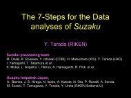
XIS0 XIS1 XIS2 XIS310 -1 1 1010 -1 1 1010 -1 1 1010 -1 1 10888866664444DETY [ arcmin ]20-2DETY [ arcmin ]20-2DETY [ arcmin ]20-2DETY [ arcmin ]20-2-4-4-4-4-6-6-6-6-8-8 -6 -4 -2 0 2 4 6 8DETX [ arcmin ]-8-8 -6 -4 -2 0 2 4 6 8DETX [ arcmin ]-8-8 -6 -4 -2 0 2 4 6 8DETX [ arcmin ]-8-8 -6 -4 -2 0 2 4 6 8DETX [ arcmin ]Fig. 12. Image, Point-Spread Function (PSF), and EEF of the four XRT-I modules in the focal plane.All the images are binned with 2×2 pixels followed by being smoothed with a Gaussian with a sigma of3 pixels, where the pixel size is 24 µm. <strong>The</strong> EEF is normalized to unity at the edge of the CCD chip (asquare of 17. ′ 8 on a side). With this normalization, the HPD of the XRT-I0 through I3 is 1. ′ 8, 2. ′ 3, 2. ′ 0,and 2. ′ 0, respectively.was taken with XIS3 in the 2.5–5.5 keV band when the Crab Nebula is offset at (Det-X,Det-Y)=(−20 ′ ,0 ′ ). <strong>The</strong> left and central panels show simulated st<strong>ray</strong> light images without and with thepre-collimator, respectively, of a monochromatic point source of 4.5 keV being located at thesame off-axis angle. <strong>The</strong> ghost image seen in the left half of the field of view is due to the“secondary reflection”. Although the “secondary reflection” cannot be completely diminishedat the off-axis angle of 20 ′ (§ 2.3), the center of the field of view is nearly free from st<strong>ray</strong>light. <strong>The</strong> semi-circular bright region in the middle panel, starting from (Det-X, Det-Y) =(−8. ′ 9,+6. ′ 5) through ∼(0 ′ ,0 ′ ) where the image becomes fainter, and ending up at (−8. ′ 9,−6. ′ 5),originates from the innermost secondary reflector, because the space between the innermostreflector and the inner wall of the telescope housing is much larger than the reflector-reflectorseparation. This semi-circular bright region is marginally visible in the real Crab Nebulaimage in the right panel. Another remarkable difference between the simulation and the realobservation is the location of the brightest area; in the simulation, the left end of the image19