2006-34: The X-ray Telescope onboard Suzaku - HEASARC - NASA
2006-34: The X-ray Telescope onboard Suzaku - HEASARC - NASA
2006-34: The X-ray Telescope onboard Suzaku - HEASARC - NASA

You also want an ePaper? Increase the reach of your titles
YUMPU automatically turns print PDFs into web optimized ePapers that Google loves.
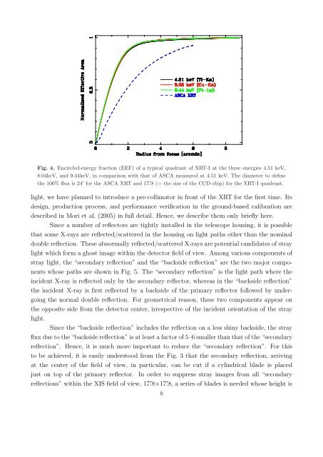
Fig. 4. Encircled-energy fraction (EEF) of a typical quadrant of XRT-I at the three energies 4.51 keV,8.04keV, and 9.44keV, in comparison with that of ASCA measured at 4.51 keV. <strong>The</strong> diameter to definethe 100% flux is 24 ′ for the ASCA XRT and 17. ′ 8 (= the size of the CCD chip) for the XRT-I quadrant.light, we have planned to introduce a pre-collimator in front of the XRT for the first time. Itsdesign, production process, and performance verification in the ground-based calibration aredescribed in Mori et al. (2005) in full detail. Hence, we describe them only briefly here.Since a number of reflectors are tightly installed in the telescope housing, it is possiblethat some X-<strong>ray</strong>s are reflected/scattered in the housing on light paths other than the nominaldouble reflection. <strong>The</strong>se abnormally reflected/scattered X-<strong>ray</strong>s are potential candidates of st<strong>ray</strong>light which form a ghost image within the detector field of view. Among various components ofst<strong>ray</strong> light, the “secondary reflection” and the “backside reflection” are the two major componentswhose paths are shown in Fig. 5. <strong>The</strong> “secondary reflection” is the light path where theincident X-<strong>ray</strong> is reflected only by the secondary reflector, whereas in the “backside reflection”the incident X-<strong>ray</strong> is first reflected by a backside of the primary reflector followed by undergoingthe normal double reflection. For geometrical reason, these two components appear onthe opposite side from the detector center, irrespective of the incident orientation of the st<strong>ray</strong>light.Since the “backside reflection” includes the reflection on a less shiny backside, the st<strong>ray</strong>flux due to the “backside reflection” is at least a factor of 5–6 smaller than that of the “secondaryreflection”. Hence, it is much more important to reduce the “secondary reflection”. For thisto be achieved, it is easily understood from the Fig. 3 that the secondary reflection, arrivingat the center of the field of view, in particular, can be cut if a cylindrical blade is placedjust on top of the primary reflector. In order to suppress st<strong>ray</strong> images from all “secondaryreflections” within the XIS field of view, 17. ′ 8×17. ′ 8, a series of blades is needed whose height is8