Schraubenspindelpumpe Baureihe CK Screw Pump Series CK
Schraubenspindelpumpe Baureihe CK Screw Pump Series CK
Schraubenspindelpumpe Baureihe CK Screw Pump Series CK
- No tags were found...

Create successful ePaper yourself
Turn your PDF publications into a flip-book with our unique Google optimized e-Paper software.
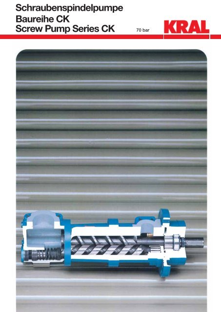
<strong>Schraubenspindelpumpe</strong><strong>Baureihe</strong> <strong>CK</strong><strong>Screw</strong> <strong>Pump</strong> <strong>Series</strong> <strong>CK</strong>70 bar1
AnwendungsbereichKRAL <strong>Schraubenspindelpumpe</strong>n werden verwendet zumFördern von Schmierölen, Hydraulikölen und anderenschmierenden Flüssigkeiten.Haupteinsatzgebiete sind alle Industriebereiche, z. B. alsSchmierölpumpen für Getriebe, Motoren und Turbinen,Industriehydraulik, Schiffshydraulik, Aufzugshydraulik undMaschinenbauindustrie.Vorteile der <strong>Schraubenspindelpumpe</strong>KRAL <strong>Schraubenspindelpumpe</strong>n bieten im Vergleichzu anderen <strong>Pump</strong>enbauarten hohe Förderleistungbei geringem Platzbedarf. Das gilt besonders beihohem Differenzdruck. Die <strong>Pump</strong>en sind selbstansaugend,fördern pulsationsarm und sind gut regelbar.Wahlweise haben die <strong>CK</strong>-<strong>Pump</strong>en ein innenliegendesSicherheitsventil.Technische DatenDrehsinn: rechts vom Antrieb gesehen.Fördermenge: 3 – 1.750 l/min.Betriebsdruck: 70 bar.ab Größe 550 max. 40 bar.Zulaufdruck: 6 bar.Temperatur: 80 °C.Viskosität: 5.000 mm 2 /s.Höhere Werte auf Anfrage.TypenschlüsselBeispiel:<strong>CK</strong>C – 880.DAA.0000011) Typen: <strong>CK</strong>C <strong>Pump</strong>emit freiem Wellenende2) Trennzeichen3) Fördermenge in l/min bei 1.450 min –14) Trennzeichen5) Varianten:Variante D: Druckstufe VentilA: 0 – x barB: x – y barC: y – z barD: z – 40 barZ: ohne VentilX: SonderausführungVariante A: Anbauteile, saugseitigA: mit SauggehäuseB: mit SaugfilterC: mit Anschluß für SaugrohrZ: ohne AnbauteileX: SonderausführungVariante M: Material GehäuseA: SilafontX: Sonderausführung6) Trennzeichen7) VersionsindexSicherheitsventilKRAL <strong>Schraubenspindelpumpe</strong>n können auch mitSicherheitsventil geliefert werden. Das Ventil dient zumSchutz der <strong>Pump</strong>e vor Überlastung und darf nicht alsSteuer- und Regelventil eingesetzt werden.Einsatzgrenzen siehe Seite 14.ApplicationKRAL screw pumps are applied to deliver lubricating oils,hydraulic oils and other non aggressive liquids.Main areas of application are all ranges of industry, e.g.lubrication oil pumps for gears, motors and turbines,industry hydraulic, ship hydraulic, elevator, hydraulic andmachine building industry.Advantages of screw pumpsCompared to other types of pumps, KRAL screw pumpsoffer high capacity without taking up much space.This applies in particular at high differential pressure.The pumps are self-priming, with low pulsation deliveryand can be easily regulated. Optionally have all <strong>CK</strong>pumpsan internal safety valve.Technical dataRotation:Capacity:Pressure:Suction pressure:Operating temperature: 80 °C.Viscosity:5.000 mm 2 /s.Higher values on request.Type keySafety valveclockwise from coupling end.3 – 1.750 l/min.70 bar.from size 550 max. 40 bar.6 bar.Sample:<strong>CK</strong>C – 880.DAA.0000011) Model: <strong>CK</strong>C <strong>Pump</strong>with free shaft end2 Divider3) Capacity in l/min at 1.450 min –14) Divider5) Options:Option D: Pressure range valveA: 0 – x barB: x – y barC: y – z barD: z – 40 barZ: without valveX: special designOption A: Attachment parts, suction sideA: with suction casingB: with suction filterC: with connection for suction pipeZ: without attachment partsX: special designOption M: Material casingA: silafontX: special6) Divider7) Version indexKRAL screw pumps can be supplied with a safetyvalve. The valve protects the pump against overpressureand must not be used as a control valve.Operation limits see page 14.2
Materialien:Förderspindeln: Stahl nitriert.<strong>Pump</strong>engehäuse: Silafont.Flanschdeckel: GG 20.Anschluß für GG 20 bis Größe 118.Saugrohr: Stahl ab Größe 160.Sauggehäusemit Ventil: GG 20.ohne Ventil: GG 20.Saugfilter: Stahl/MW 0,5 mm.Wellendichtringe: NBR, FKM.Materials:screw spindles: steel nitrated.pump casing: silafont.flange cover: GG 20.connection for GG 20 up to size 118.suction pipe: steel over size 160.suction casingwith valve: GG 20.without valve: GG 20.suction filter: steel/MW 0,5 mm.radial shaft seal NBR, FKM.TypenübersichtTypes.2.900 min –1 ,.2,900 min –1 ,<strong>Pump</strong>ing capacity, -behaviour3
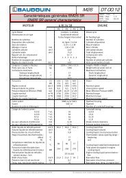
Flanschpumpe mit eingebautem Filter fürBehältereinbau mit Flanschlaterne,Kupplung und Drehstrommotor.Flange pumpe with mounted filter for tankapplication with flange lantern, coupling,and three phase A.C. motor.Flanschpumpe mit Saugrohr und Filtermit Rückschlagventil, Flanschlaterne,Kupplung und Drehstrommotor.Flange pump with suction pipe and filterwith non return valve, flange lantern,coupling, and three phase A.C. motor.Flanschpumpe mit angebautem Filter,Druckrohr mit Sicherheitsventil,Montageplatte, Flanschlaterne,Kupplung und Drehstrommotor.Flange pump with mounted filter, pressurepipe with safety valve, mountingplate, flange lantern, coupling, and threephase A.C. motor.5
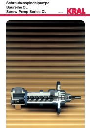
SchnittbildSection drawingSaugfilterSuction filterAnschluß für SaugrohrConnection for suction pipebis zurGröße C 118up to size C 118ab Größe C 160from Size C 160****** nur bei Größen C 55 – C 85only size C 55 – C 85SauggehäuseSuction casing+**859 ++ * ab Größe C 370from size C 370Sauggehäuse mit SicherheitsventilSuction casing with safety valve+bis Größe C 42up to size C 42++ab Größe C 55from size C 55** nicht enthalten in GrößeC 55, 74, 85, 105, 118not incl. in sizeC 55, 74, 85, 105, 1186
<strong>Pump</strong>e042 Ausgleichszylinder049 Lagerbuchse062 Distanzscheibe065 Segmentscheibe070 Abschlussdeckel074 Flanschdeckel* 222,1 Dichtung* 222,2 Dichtung454 Dichtkantenring669 Spindelsatz* 735 Kupferdichtung* 745 Dichtlippenring* 817 Kugellager859 Spannhülse866 Passfeder869 Wellensicherungsring870 Wellensicherungsring879,1 Zylinderstift879,2 Zylinderstift884 Gewindestift915,1 Zylinderschraube*1037 Lagerbuchsenset<strong>Pump</strong>042 balance piston049 bearing shell062 spacer065 segmental wheel070 end cover074 flange cover* 222.1 gasket* 222,2 gasket454 joint ring669 spindle set* 735 cooper seal ring* 745 seal lip ring* 817 bearing859 clamping sleeve866 key869 circlip870 circlip879,1 straight pin879,2 straight pin884 set screw915,1 socket screw*1037 bearing shell setAnbauteileSaugfilter . . . . . F131 <strong>Pump</strong>engehäuse416 Schlauchklemme610 SaugsiebAnschluss für Saugrohr . . . . . V090 Saugdeckel131 <strong>Pump</strong>engehäuse* 222,3 Dichtung416 Schlauchklemme610 Saugsieb915,3 ZylinderschraubeSauggehäuse . . . . . S131 <strong>Pump</strong>engehäuse137,1 Sauggehäuse* 222,3 Dichtung915,2 ZylinderschraubeSauggehäuse mit Ventil . . . . . U131 <strong>Pump</strong>engehäuse137,2 Sauggehäuse mit Ventil166 Verstellschraube* 222,3 Dichtung304 Ventilkegel* 730 Flachdichtung751 Druckfeder908 Verschlussschraube915,2 ZylinderschraubeAccessoriesSuction filter . . . . . F131 pump casing416 tube clip610 suction sieveConnection for suction pipe . . . . . V090 suction cover131 pump casing* 222,3 gasket416 tube clip610 suction sieve915,3 socket screwSuction casing . . . . . S131 pump casing137,1 suction casing* 222,3 gasket915,2 socket screwSuction casing with valve . . . . . U131 pump casing137,2 suction casing with valve166 adjusting screw* 222,3 gasket304 valve cone* 730 flat gasket751 spring908 adjusting screw915,2 socket screw*empfohlene Ersatzteile*recommended spare parts7
MassblattDimensions<strong>CK</strong>CR . . . F<strong>CK</strong>-<strong>Pump</strong>e mit Saugsieb<strong>CK</strong>-pump with suction filter<strong>Pump</strong>epump5/10Flansch<strong>Pump</strong>enmaßeWellenendeflangepump dimensionsshaft endingDNd B1 B2 H1 S2 D1 D2 D3 D4 S1 L1 L2 L3 L4 L5 L6 LP d l t uR3/4"- - 32 - 76 95 115 76 9 5 77 13 42 174 50 251 14 30 16 5Änderungen vorbehalten Subject to change without noticeMaße in mm Dimension in mm550/880 370/450 235/275 160/210 105/118 55/85 32/42 15/26SAE1"SAE1"SAE11/4"SAE11/2"SAE11/2"SAE21/2"SAE21/2"SAE3"52 26 4452 2644M10M1059 30 44 M10 110 13083 105 128 76 9 5 76 15 46 200 50 277 19 35 21,5859233 50 311 19 35 21,5 670 36 50 M12 120 152 179 120 14 5 101 19 62 323 70 423 32 55 27 870 36 6389 51 M1283 105 12863 150 1805 78149 100 11 5 103 17 59 297 70 400 32 55M12 135 175 202 140 14 5 105 20 63 366 70 471 32 5535 1089 51 76 M12 165 205 243 172 18 5 113 25,5 91 463 80 576 32 55 35 10106 62 77 M16 190 230 266 195 18 5 143 28 111 536 80 679 42 75 45 12155021,5217 146 18 5 106 22,5 87 434 80 541 32 55 35 10668
<strong>CK</strong>-Aggregat mit Saugsieb<strong>CK</strong>-aggregate withsuction filterDruckanschlussGröße <strong>CK</strong> 5 – <strong>CK</strong> 10 – R 3 /4˝Größe <strong>CK</strong> 15 – <strong>CK</strong> 880 SAE 3000 PSISAE – Flanschen sind als Einschraubflanschoder Anschweißflansch lieferbar(Maße siehe Seite 15).Pressure connectionSize <strong>CK</strong> 5 – <strong>CK</strong> 10 – R 3 /4˝Size <strong>CK</strong> 15 – <strong>CK</strong> 880 SAE 3000 PSISAE – flanges can be delivered asthreaded flange or as welded flange(dimensions see page 15).Änderungen vorbehalten Subject to change without noticeMaße in mm Dimension in mm* Depending on motor manufacturerFlanschAggregat<strong>Pump</strong>e Motorflangeaggregatepump motorDNd B1 B2 S1 D1 D2 D3 L1 L2 L3 L4 L5 LL LM* LG* B380 145 200 326 178 16 152 247 573 13490S/90L R145 200 326 178 16 152 265 591 140- - - 76 50 174100L/112M 3/4"190 250 349 199 18 175 325 674 178132S/132M 234 300 370 218 20 196 430 800 20680 145 200 340 170 16 140 247 587 13490S/90L 145 200 340 170 16 140 265 605 140SAE100L/112M 52 26 M10 190 250 76 359 187 18 50 200 159 325 684 1781"132S/132M 234 300 396 222 20 196 430 826 206160M/160L 260 350 404 225 25 204 565 969 21080 145 200 373 174 16 140 247 620 13490S/90L 145 200 373 174 16 140 265 638 140SAE100L/112M 52 26 M10 190 250 85 392 191 18 50 233 159 325 717 1781"132S/132M 234 300 429 226 20 196 430 859 206160M/160L 260 350 437 229 25 204 565 1002 210100L/112M 190 250 472 216 18 175 325 797 178132S/132M 234 300 493 235 20 196 430 923 206SAE160M/160L 59 30 M10 260 350 100 525 262 25 70 297 228 565 1090 21011/4"180M/180L 260 350 553 290 25 256 630 1183 280200L 300 400 553 290 25 256 660 1213 305100L/112M 190 250 498 219 18 175 325 823 178132S/132M 234 300 519 238 20 196 430 949 206160M/160L 260 350 551 265 25 228 565 1116 210SAE180M/180L 70 36 M12 260 350 120 579 558 25 70 323 256 630 1209 28011/2"200L 300 400 579 558 25 256 660 1239 305225/2 350 450 557 271 25 234 710 1267 335225/4 350 450 608 322 25 285 705 1313 335132S/132M 234 300 562 239 20 196 430 996 206160M/160L 260 350 622 294 25 256 565 1187 210180M/180L SAE260 350 622 294 25 256 630 1252 28070 36 M12 14070 366200L 11/2"300 400 622 294 25 256 660 1282 305225/2 350 450 628 300 25 262 710 1338 335225/4 350 450 651 323 25 285 705 1356 335132S/132M 234 300 630 263 20 196 430 1060 206160M/160L 260 350 690 318 25 256 565 1255 210180M/180L SAE260 350 690 318 25 256 630 1320 28089 51 M12 146 80 434200L 21/2"300 400 690 318 25 256 660 1350 305225/2 350 450 696 324 25 262 710 1406 335225/4 350 450 719 347 25 285 705 1424 335132S/132M 234 300 673 281 20 210 430 1103 206160M/160L 260 350 719 322 25 256 565 1284 210180M/180L SAE260 350 719 322 25 256 630 1349 28089 51 M12 172 80 463200L 21/2"300 400 719 322 25 256 660 1379 305225/2 350 450 725 328 25 262 710 1435 335225/4 350 450 748 351 25 285 705 1453 335160M/160L 260 350 792 342 25 256 565 1357 210180M/180L 260 350 792 342 25 256 630 1422 280200L 300 400 809 359 25 273 660 1469 305SAE225/2 106 62 M16 350 450 195 821 371 25 80 536 285 710 1531 3353"225/4 350 450 838 388 25 302 705 1543 335250/2 450 550 851 400 26 315 770 1621 370250/4 450 550 851 400 26 315 770 1621 3705/1015/2632/4255/85105/118160/210235/275370/450550/8809
MassblattDimensions<strong>CK</strong>CR . . . V<strong>CK</strong>-<strong>Pump</strong>e mit Saugrohranschluss<strong>CK</strong>-pump with connection for suction pipeÄnderungen vorbehalten Subject to change without noticeMaße in mm Dimension in mm<strong>Pump</strong>epump5/1015/2632/4255/85105/118160/210235/275370/450550/880Flansch<strong>Pump</strong>enmaßeWellenendeflangepump dimensionsshaft endingDNd B1 B2 H1 S2 D1 D2 D3 S1 L1 L2 L3 L4 L5 LP E1 E2 d l t uR3/4"SAE1"SAE1"SAE11/4"SAE11/2"SAE11/2"SAE21/2"SAE21/2"SAE3"-52 2670- 32 -52 26 443670 36 63M10768344 M10 8359 30 44 M10 110 13050 M12 120 15295 1151051051281281491799 5 77 139 5 76 159 5 78 15R11 5 103 17 59 280 383 - 32 5511/2"R14 5 101 19 62 321 421 - 32 552"M12 135 175 202 14 5 105 20 63 344 450 - 76,1 32 5589 51 63 M12 150 18021718 5 106 23 87 394 500 - 88,9 32 55 35 1089 51 76 M12 165 205 243 18 5 113 26 91 445 558 - 114,3 32 55 35 10106 62 77 M16 190 230 266 18 5 143 28 111 520 660 - 139,7 42 75 45 124215946 18650228236262306R1"R1"R11/4"-1416 5- 19 35 21,5- 19303521,5621,5 6627 835 1010
<strong>CK</strong>-Aggregat mit Saugrohranschluss<strong>CK</strong>-aggregate with for suction pipeDruckanschlussGröße <strong>CK</strong> 5 – <strong>CK</strong> 10 – R 3 /4˝Größe <strong>CK</strong> 15 – <strong>CK</strong> 880 SAE 3000 PSISAE – Flanschen sind als Einschraubflanschoder Anschweißflansch lieferbar.(Maße siehe Seite 15)Pressure connectionSize <strong>CK</strong> 5 – <strong>CK</strong> 10 – R 3 /4˝Size <strong>CK</strong> 15 – <strong>CK</strong> 880 SAE 3000 PSISAE – flanges can be delivered asthreaded flange or as welded flange.(dimensions see page 15)ttEintauchtiefe ist beiBestellung anzugebenIn case of order pleasemention depth of immersidÄnderungen vorbehalten Subject to change without noticeMaße in mm Dimension in mm* Depending on motor manufacturerFlanschAggregat<strong>Pump</strong>e Motorflangeaggregatpump motorDNd B1 B2 S1 D1 D2 D3 D4 L1 L2 L3 L4 L5 LL LM* LG* B380 145 200 311 178 16 152 247 558 13490S/90L R145 200 R 311 178 16 152 265 576 140- - - 76 50 159100L/112M 3/4"190 250 1" 334 199 18 175 325 659 178132S/132M 234 300 355 218 20 196 430 785 20680 145 200 326 170 16 140 247 573 13490S/90L 145 200 326 170 16 140 265 591 140SAER100L/112M 52 26 M10 190 250 76 345 187 18 50 186 159 325 670 1781"1"132S/132M 234 300 382 222 20 196 430 812 206160M/160L 260 350 390 225 25 204 565 955 21080 145 200 368 174 16 140 247 615 13490S/90L 145 200 368 174 16 140 265 633 140SAER100L/112M 52 26 M10 190 250 85 387 191 18 50 228 159 325 712 1781"11/4"132S/132M 234 300 424 226 20 196 430 854 206160M/160L 260 350 432 229 25 204 565 997 210100L/112M 190 250 455 216 18 175 325 780 178132S/132M 234 300 476 235 20 196 430 906 206SAER160M/160L 59 30 M10 260 350 100 508 262 25 70 280 228 565 1073 21011/4"11/2"180M/180L 260 350 536 290 25 256 630 1166 280200L 300 400 536 290 25 256 660 1196 305100L/112M 190 250 496 219 18 175 325 821 178132S/132M 234 300 517 238 20 196 430 947 206160M/160L 260 350 549 265 25 228 565 1114 210SAER180M/180L 70 36 M12 260 350 120 577 558 25 70 321 256 630 1207 28011/2"2"200L 300 400 577 558 25 256 660 1237 305225/2 350 450 555 271 25 234 710 1265 335225/4 350 450 606 322 25 285 705 1311 335132S/132M 234 300 540 239 20 196 430 970 206160M/160L 260 350 600 294 25 256 565 1165 210180M/180L SAE260 350 600 294 25 256 630 1230 28070 36 M12 140 76,170 344200L 11/2"300 400 600 294 25 256 660 1260 305225/2 350 450 606 300 25 262 710 1316 335225/4 350 450 629 323 25 285 705 1334 335132S/132M 234 300 590 263 20 196 430 1020 206160M/160L 260 350 650 318 25 256 565 1215 210180M/180L SAE260 350 650 318 25 256 630 1280 28089 51 M12 146 88,980 394200L 21/2"300 400 650 318 25 256 660 1310 305225/2 350 450 656 324 25 262 710 1366 335225/4 350 450 679 347 25 285 705 1384 335132S/132M 234 300 655 281 20 210 430 1085 206160M/160L 260 350 701 322 25 256 565 1266 210180M/180L SAE260 350 701 322 25 256 630 1331 28089 51 M12 172 114,380 445200L 21/2"300 400 701 322 25 256 660 1361 305225/2 350 450 707 328 25 262 710 1417 335225/4 350 450 730 351 25 285 705 1435 335160M/160L 260 350 776 342 25 256 565 1341 210180M/180L 260 350 776 342 25 256 630 1406 280200L 300 400 793 359 25 273 660 1453 305SAE225/2 106 62 M16 350 450 195 139,7 805 371 25 80 520 285 710 1515 3353"225/4 350 450 822 388 25 302 705 1527 335250/2 450 550 835 400 26 315 770 1605 370250/4 450 550 835 400 26 315 770 1605 3705/1015/2632/4255/85105/118160/210235/275370/450550/88011
MassblattDimensions<strong>CK</strong>CR . . . S/U<strong>CK</strong>-<strong>Pump</strong>e mit Saugehäuse (mit oder ohne Überströmventil)<strong>CK</strong>-pump with suction (with or without valve)Änderungen vorbehalten Subject to change without noticeMaße in mm Dimension in mm<strong>Pump</strong>epump5/1015/2632/4255/ 85105/118160/210235/275370/450550/880Flansch<strong>Pump</strong>enmaßeWellenendeflangepump dimensionsshaft endingDNs B3 B4 H2 S3 DNd B1 B2 H1 S2 D1 D2 D3 S1 L1 L2 L3 L4 L5 L6 LP B5 S4 d l t uSAER26 52 50 M101"3/4"- - 32 - 76 95 115 9 5 77 13 42 128 - 292 - - 14 30 16 5SAE1"SAE11/4"SAE11/2"SAE2"SAE21/2"SAE3"SAE4"SAE5"26 52 5030 5936 7043 7851 8961M10M10SAE1"SAE1"SAE66 M12 59 30 44 M10 110 130 149 11 5 103 17 59 222 286 434 4511/4"SAE76 M12 70 36 50 M12 120 152 179 14 5 101 19 62 250 326 467 4511/2"SAE86 M12 70 36 63 M12 135 175 202 14 5 105 20 63 252 375 536 5011/2"SAE62 106 91 M16 89 51 63 M12 150 180 217 18 5 106 22,5 87 336 438 607 5021/2"78 130 106 M16 SAE21/2"92 152 119 M16 SAE3"52 26 44 M10 83 105 128 9 5 76 15 46 151 -52 2644 M10 83 105 128 9 5 78 15 50 184 -89 51 76 M12 165 205 243 18 5 113 25,5 91 388 502 685 50106 62 77 M16 190 230 266 18 5 143 28 111 450 577 806 50313356- - 19- - 19 35 21,5 6M8M8M10M10M10M103521,5 632 55 21,5 632 55 27 832 55 35 1032 55 35 1032 55 35 1042 75 75 1212
<strong>CK</strong>-Aggregat mit Sauggehäuse (mit oder ohne Überströmventil)<strong>CK</strong>-aggregate with suction (with or without valve)<strong>CK</strong>CR 5 – <strong>CK</strong>CR275 mit Motor BG bis 180<strong>CK</strong>CR 5 – <strong>CK</strong>CR275 with motor BG to 180<strong>CK</strong>CR370 – <strong>CK</strong>CR880 mit Motor BG von 160 bis 200<strong>CK</strong>CR370 – <strong>CK</strong>CR880 with motor BG from 160 to 200<strong>CK</strong>CR 55 – <strong>CK</strong>CR210 mit Motor BG 200<strong>CK</strong>CR 55 – <strong>CK</strong>CR210 with motor BG 200<strong>CK</strong>CR105 – <strong>CK</strong>CR880 mit Motor BG von 225 bis 250<strong>CK</strong>CR105 – <strong>CK</strong>CR880 with motor BG from 225 to 250SauganschlussSAE – 3000 PSIDruckanschlussGröße <strong>CK</strong> 5 – <strong>CK</strong> 10 – R 3 /4˝Größe <strong>CK</strong> 15 – <strong>CK</strong> 880 SAE 3000 PSISAE – Flansche sind als Einschraubflanschoder Anschweißflanschlieferbar.(Maße siehe Seite 15)Suction connectionSAE – 3000 PSIPressure connectionSize <strong>CK</strong> 5 – <strong>CK</strong> 10 – R 3 /4˝Size <strong>CK</strong> 15 – <strong>CK</strong> 880 SAE 3000 PSISAE – flanges can be delivered asthreaded flange or as welded flange.(dimensions see page 15)Änderungen vorbehalten Subject to change without noticeMaße in mm Dimension in mm# B35 Motor ab BG225* depending on motor manufacturerFlansch<strong>Pump</strong>eFuss FußAggregat<strong>Pump</strong>e Motorflangepumpfootaggregatepump motorDNs DNd H1 H2 L1 L2 L3 L4 L5 L6 L7 B1 B2 S1 H3 H4 D1 LL LM* LG80 115 60 90 19 180 210 11 112 12 200 152 247 61490S/90L SAE R115 60 90 19 180 210 11 112 12 200 152 265 63232 50 42 128 215100L/112M 1" 3/4"118 60 97 39 220 250 14 132 15 250 175 325 715132S/132M 118 80 116 40 260 290 14 160 18 300 196 430 84180 107 60 90 19 180 210 11 112 12 200 140 247 62490S/90L 107 60 90 19 180 210 11 112 12 200 140 265 642SAE SAE100L/112M 44 50 46 151 237 106 60 97 39 220 250 14 132 15 250 159 325 7211" 1"132S/132M 122 80 116 40 260 290 14 160 18 300 196 430 863160M/160L 95 110 150 45 300 340 18 180 22 350 204 565 100680 111 60 90 19 180 210 11 112 12 200 140 247 66590S/90L 111 60 90 19 180 210 11 112 12 200 140 265 683SAE SAE100L/112M 44 61 50 184 278 110 60 97 39 220 250 14 132 15 250 159 325 76211/4" 1"132S/132M 126 80 116 40 260 290 14 160 18 300 196 430 904160M/160L 99 110 150 45 300 340 18 180 22 350 204 565 1047100L/112M 135 60 97 39 220 250 14 132 15 250 175 325 831132S/132M 135 80 116 40 260 290 14 160 18 300 196 430 957SAE SAE160M/160L 44 66 59 222 331 132 110 150 45 300 340 18 180 22 350 228 565 112411/2" 11/4"180M/180L 160 110 150 45 300 340 18 180 22 350 256 630 1217200L 190 300 350 125 350 400 18 260 20 400 256 660 1247100L/112M 138 60 97 39 220 250 14 132 15 250 175 325 905132S/132M 138 80 116 40 260 290 14 160 18 300 196 430 1031160M/160L 135 110 150 45 300 340 18 180 22 350 228 565 1198SAE SAE180M/180L 50 76 62 250 405 163 110 150 45 300 340 18 180 22 350 256 630 12912" 11/2"200L 193 300 350 125 350 400 18 260 20 400 256 660 1321#225/2 445 311 407 149 356 435 19 225 27 450 234 710 1349#225/4 496 286 382 149 356 435 19 225 27 450 285 705 1395132S/132M 139 80 116 40 260 290 14 160 18 300 196 430 1057160M/160L 164 110 150 45 300 340 18 180 22 350 256 565 1252180M/180L SAE SAE164 110 150 45 300 340 18 180 22 350 256 630 131763 86 63 252 431200L 21/2" 11/2"194 300 350 125 350 400 18 260 20 400 256 660 1347#225/2 474 311 407 149 356 435 19 225 27 450 262 710 1403#225/4 497 286 382 149 356 435 19 225 27 450 285 705 1421132S/132M 163 80 116 40 260 290 14 160 18 300 196 430 1127160M/160L 188 110 150 45 300 340 18 180 22 350 256 565 1322180M/180L SAE SAE188 110 150 45 300 340 18 180 22 350 256 630 138763 91 87 336 501200L 3" 21/2"214 300 350 129 350 400 18 260 20 400 256 660 1417#225/2 498 311 407 149 356 435 19 225 27 450 262 710 1473#225/4 521 286 382 149 356 435 19 225 27 450 285 705 1491132S/132M 181 80 116 40 260 290 14 160 18 300 210 430 1212160M/160L 232 265 305 115 300 350 18 235 18 350 256 565 1393180M/180L SAE SAE232 265 305 115 300 350 18 235 18 350 256 630 145876 106 91 388 572200L 4" 21/2"222 300 350 125 350 400 18 260 20 400 256 660 1488#225/2 502 311 407 149 356 435 19 225 27 450 262 710 1544#225/4 525 286 382 149 356 435 19 225 27 450 285 705 1562160M/160L 252 265 305 115 300 350 18 235 18 350 256 565 1484180M/180L 252 265 305 115 300 350 18 235 18 350 256 630 1549200L 259 300 350 125 350 400 18 260 20 400 273 660 1579SAE SAE#225/2 77 119 111 450 663 545 311 407 149 356 435 19 225 27 450 285 710 16585" 3"#225/4 562 286 382 149 356 435 19 225 27 450 302 705 1670#250/2 594 349 458 168 581 636 24 280 33 550 315 770 1748#250/4 594 349 458 168 581 636 24 280 33 550 315 770 174832/42 15/26 5/1055/ 85105/118160/210235/275370/450550/88013
SicherheitsventilSafety valveDas Sicherheitsventil ist ein direkt gesteuertes, federbelastetesUmlaufventil und dient zum Schutz der <strong>Pump</strong>e oder Aggregatevor Überlastung. Als Steuer- oder Regelventil darf es nichteingesetzt werden. Der Öffnungsdruck wird standardmäßig10–15 % über dem angegebenen Betriebsdruck eingestellt.The safety valve is a direct controlled springweighed bypassvalve and protects the pump or aggregate against overpressure.It must not be used as a control valve.The opening pressure of the valve is adjusted as a standardabout 10–15 % over the operating pressure.WirkungsweiseBeim Überschreiten des vorgegebenen Druckes wird derVentilkegel gegen die Kraft der Ventilfeder angehoben,so dass das Fördermedium von der Druckseite zur Saugseiteüberströmen kann.Principle of operationIf the noticed pressure is exceeded, the valve cone lifts againstthe force of the valve spring so that the pumping medium canflow from the pressure side to the suction side of the pump.Einsatzgrenzenmax. Einstelldruck<strong>Pump</strong>engrößen 5 – 26 bis zu 50 bar.32 – 85 bis zu 35 bar.105 – 118 bis zu 30 bar.160 – 210 bis zu 25 bar.235 – 450 bis zu 20 bar.550 – 880 bis zu 10 bar.Höhere Werte auf Anfrage.Operation limitsMax. test pressure<strong>Pump</strong> size 5 – 26 up to 50 bar.32 – 85 up to 35 bar.105 – 118 up to 30 bar.160 – 210 up to 25 bar.235 – 450 up to 20 bar.550 – 880 up to 10 bar.Higher values on request.14Einstellen des VentilsVor dem Verstellen muss die Verschlussschraube (908) entferntwerden. Jetzt ist die Verstellschraube (166) frei zugänglich undkann mit einem Innensechskantschlüssel verdreht werden.Drehen nach rechts (im Uhrzeigersinn) erhöht den Öffnungsdruck,drehen nach links vermindert den Öffnungsdruck.Operating instructionsBefore adjusting, the head bolt (908) must be screwed out.Now the adjusting screw (166) can be turned by a hexagonsocket screw key.Turning right (clockwise) is increasing the opening pressure,turning left is reducing the opening pressure.
SAE – GegenflanschSAE – Counter flangeSAE-threaded flangePressure up to 210 bar = 3000 PSIArtikel-Nr.Article no.SAE-welded flangePressure up to 210 bar = 3000 PSIArtikel-Nr.Article no.15
16Leistungstabelle 50 HzPerformance characteristics 50 Hz
18Leistungstabelle 60 HzPerformance characteristics 60 Hz
KRAL AGBildgasse 40, Industrie Nord6890 Lustenau, AustriaTel.: +43 / 55 77 / 8 66 44-0Fax.: +43 / 55 77 / 8 84 33www.kral.at, kral@kral.at<strong>Schraubenspindelpumpe</strong>n<strong>Baureihe</strong> Kmax. Druck 16 barmax. Fördermenge 2900 l/min<strong>Screw</strong> pumpsseries Kmax. pressuremax. capacity16 bar2900 l/min<strong>Schraubenspindelpumpe</strong>n<strong>Baureihe</strong> Doppelstationenmax. Druck 40 barmax. Fördermenge 7000 l/h<strong>Screw</strong> pumpsseries double-stationsmax. pressure 40 barmax. capacity 7000 l/hAnwendung:Für Heizöle (Leicht bisSchwer) als Transfer-Ringleitungs-und Brennerpumpen.Für Schmier- undHydrauliköle.Application:For fuel oil (light and heavy)as transfer, circular pipelineandburner pumps. For lubricationand hydraulic oil.Anwendung:Für Heizöle (Leicht bisSchwer) als Transfer, Ringleitungs-und Brennerpumpen.Application:For fuel oil (light and heavy)as transfer, circular pipelineandburner pumps.Durchflussmesser<strong>Baureihe</strong> OMmax. Druck 420 barMeßbereich 0,1-7500 l/minAnwendung:Für FlüssigkeitenKRAL ElektronikBEM 300 und BEM 500Flowmeter systemsseries OMmax. pressure 420 barmeasuring 0,1-7500 l/minrangeApplication:For liquidsKRAL ElectronicsBEM 300 and BEM 500Anwendung:Application:– Abstimmung auf– Coordinated to theDurchfluss messgeräte und flowmeters and theirAnwendungen.applications.– Fehlerfreies Bedienen durch – Accurate handling by the useübersichtliche Menüstruktur. of a clear menu structure.– Übersichtliche, gut lesbare – Clear and easily readable theAnzeige.display.– Viele Montagemöglichkeiten. – Multiple mounting options.<strong>Schraubenspindelpumpe</strong>n<strong>Baureihe</strong> Mmax. Druck 40 barmax. Fördermenge 420 l/minAnwendung:Für Heizöle (Leichtbis Schwer) als Brennerpumpen.Für Schmier- undHydrauliköle.Überreicht durch / Presented by:<strong>Screw</strong> pumpsseries Mmax. pressuremax. capacity40 bar420 l/minApplication:For fuel oil (light and heavy)as burner pumps. For lubricationand hydraulic oil.Änderungen vorbehalten · Subject to change 07/08. Austria ExportprospektAlle Rechte vorbehalten · All rights reserved.20