

Stress Concentration Produced by Holes and Notches
Stress Concentration Produced by Holes and Notches
Stress Concentration Produced by Holes and Notches

Create successful ePaper yourself
Turn your PDF publications into a flip-book with our unique Google optimized e-Paper software.
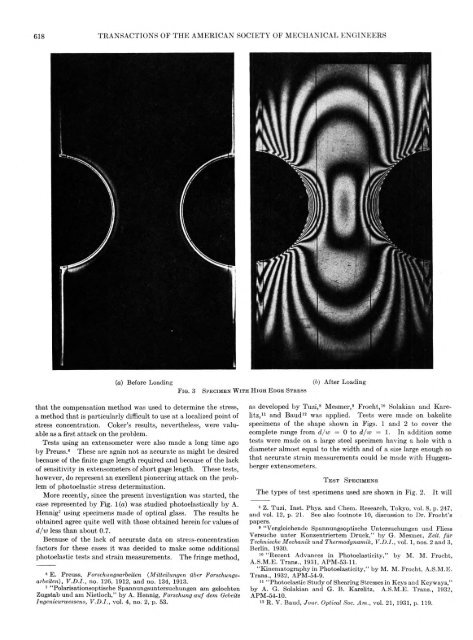
618 TRANSACTIONS OF TH E AMERICAN SOCIETY OF MECHANICAL ENGINEERS(a) Before LoadingF i g . 3that the compensation method was used to determine the stress,a method that is particularly difficult to use at a localized point ofstress concentration. Coker’s results, nevertheless, were valuableas a first attack on the problem.Tests using an extensometer were also made a long time ago<strong>by</strong> Preuss.6 These are again not as accurate as might be desiredbecause of the finite gage length required <strong>and</strong> because of the lackof sensitivity in extensometers of short gage length. These tests,however, do represent an excellent pioneering attack on the problemof photoelastic stress determination.More recently, since the present investigation was started, thecase represented <strong>by</strong> Fig. 1 (a) was studied photoelastically <strong>by</strong> A.Hennig7 using specimens made of optical glass. The results heobtained agree quite well with those obtained herein for values ofd/w less than about 0.7.Because of the lack of accurate data on stress-concentrationfactors for these cases it was decided to make some additionalphotoelastic tests <strong>and</strong> strain measurements. The fringe method,6 E. Preuss, Forschungsarbeiten (M itteilungen ilber Forschungsarbeiten),V .D .I., no. 126, 1912, <strong>and</strong> no. 134, 1913.7 “ Polarisationsoptische Spannungsuntersuehungen am gelochtenZugstab und am N ietloch,” b y A. Hennig, Forschung a u f dem GebeiteIngenieurwessens, V .D .I., vol. 4, no. 2, p. 53.S p e c i m e n W i t h H i g h E d g e S t r e s s(b) A fter Loadingas developed <strong>by</strong> Tuzi,8 Mesmer,9 Frocht,10 Solakian <strong>and</strong> Karelitz,11<strong>and</strong> Baud12 was applied. Tests were made on bakelitespecimens of the shape shown in Figs. 1 <strong>and</strong> 2 to cover thecomplete range from d/w = 0 to d/w = 1. In addition sometests were made on a large steel specimen having a hole with adiameter almost equal to the width <strong>and</strong> of a size large enough sothat accurate strain measurements could be made with Huggenbergerextensometers.T e s t S p e c i m e n sThe types of test specimens used are shown in Fig. 2.It will8 Z. Tuzi, Inst. Phys. <strong>and</strong> Chem. Research, Tokyo, vol. 8, p. 247,<strong>and</strong> vol. 12, p. 21. See also footnote 10, discussion to Dr. F rocht’spapers.9 “Vergleichende Spannungsoptische Untersuchungen und FliessVersuche u n ter K onzentriertem D ruck,” <strong>by</strong> G. M esmei, Zeit. fu rTechnische Mechanik und Thermodynamik, V .D .I., vol. 1, nos. 2 <strong>and</strong> 3,Berlin, 1930.10 “R ecent Advances in P hotoelasticity,” <strong>by</strong> M. M. Frocht,A.S.M .E. T rans., 1931, APM-53-11.“K inem atography in P hotoelasticity,” <strong>by</strong> M. M. Frocht, A.S.M .E.T rans., 1932, APM-54-9.11 “ Photoelastic Study of Shearing <strong>Stress</strong>es in Keys <strong>and</strong> Keyways,”b y A. G. Solakian <strong>and</strong> G. B. K arelitz, A.S.M .E. T rans., 1932,APM-54-10.12 R. V . B aud, Jour. Optical Soc. A m ., vol. 21, 1931, p. 119.


