Centro-Matic Lubrication System - Major Furnace Australia provides ...
Centro-Matic Lubrication System - Major Furnace Australia provides ...
Centro-Matic Lubrication System - Major Furnace Australia provides ...

Create successful ePaper yourself
Turn your PDF publications into a flip-book with our unique Google optimized e-Paper software.
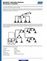
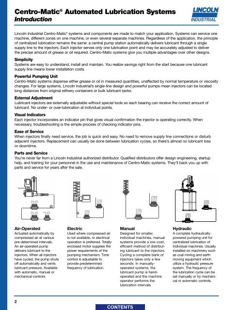
<strong>Centro</strong>-<strong>Matic</strong> ® Automated <strong>Lubrication</strong> <strong>System</strong>sIntroductionLincoln Industrial <strong>Centro</strong>-<strong>Matic</strong> ® systems and components are made to match your application. <strong>System</strong>s can service onemachine, different zones on one machine, or even several separate machines. Regardless of the application, the principleof centralized lubrication remains the same: a central pump station automatically delivers lubricant through a singlesupply line to the injectors. Each injector serves only one lubrication point and may be accurately adjusted to deliverthe precise amount of grease or oil required. <strong>Centro</strong>-<strong>Matic</strong> systems give you multiple advantages over other designs.Simplicity<strong>System</strong>s are easy to understand, install and maintain. You realize savings right from the start because one lubricantsupply line means lower installation costs.Powerful Pumping Unit<strong>Centro</strong>-<strong>Matic</strong> systems dispense either grease or oil in measured quantities, unaffected by normal temperature or viscositychanges. For large systems, Lincoln Industrial’s single-line design and powerful pumps mean injectors can be locatedlong distances from original refinery containers or bulk lubricant tanks.External AdjustmentLubricant injectors are externally adjustable without special tools so each bearing can receive the correct amount oflubricant. No under- or over-lubrication at individual points.Visual IndicatorsEach injector incorporates an indicator pin that gives visual confirmation the injector is operating correctly. Whennecessary, troubleshooting is the simple process of checking indicator pins.Ease of ServiceWhen injectors finally need service, the job is quick and easy. No need to remove supply line connections or disturbadjacent injectors. Replacement can usually be done between lubrication cycles, so there’s almost no lubricant lossor downtime.Parts and ServiceYou’re never far from a Lincoln Industrial authorized distributor. Qualified distributors offer design engineering, startuphelp, and training for your personnel in the use and maintenance of <strong>Centro</strong>-<strong>Matic</strong> systems. They’ll back you up withparts and service for years after the sale.Air-OperatedActuated automatically bycompressed air at variouspre-determined intervals.An air-operated pumpdelivers lubricant to theinjectors. When all injectorshave cycled, the pump shutsoff automatically and ventslubricant pressure. Availablewith automatic, manual ormechanical controls.ElectricUsed where compressed airis not available, or electricaloperation is preferred. Totallyenclosed motor supplies thepower requirements of thepumping mechanism. Timecontrol is adjustable toprovide predeterminedfrequency of lubrication.ManualDesigned for smaller,individual machines, manualsystems provide a low-cost,efficient method of distributinglubricant to the injectors.Cycling a complete bank ofinjectors takes only a fewseconds. In manuallyoperatedsystems, thelubricant pump is handoperatedand the machineoperator performs thelubrication intervals.HydraulicA complete hydraulicallypoweredpumping unit forcentralized lubrication ofindividual machines. Usuallyinstalled on machinery suchas coal mining and earthmoving equipment whichutilize a hydraulic pressuresystem. The frequency ofthe lubrication cycle can beset manually or by mechanicalor automatic controls.2
<strong>Centro</strong>-<strong>Matic</strong> ® Automated <strong>Lubrication</strong> <strong>System</strong>sIntroductionBasic Operating Principles of <strong>Centro</strong>-<strong>Matic</strong> ® InjectorsEach Lincoln <strong>Centro</strong>-<strong>Matic</strong> injector can be manually adjusted to discharge the precise amount of lubricant eachbearing needs. Injectors are mounted singly at each bearing, or grouped in a manifold with feedlines supplyinglubricant to the bearings. In each case, injectors are supplied with lubricant under pump pressure through a singlesupply line. Two injector types are available: one with a top adjustment and one with a side adjustment. Both typescan be used in the same circuit; their selection is made on the basis of bearing lubricant requirements.SL-1, -11, -41, -44InjectorPistonIndicatorStemInjectorPistonMeasuringChamberPassageSlideValveDischargeChamberOutletPortSlideValvePassageLubricantSupply InletStage 1 Stage 2 Stage 3 Stage 4DischargeChamberStage 1—The injector piston is in its normal, or rest position. The discharge chamber is filled with lubricant fromthe previous cycle. Under the pressure of incoming lubricant, the slide valve is about to open the passage leadingto the piston.Stage 2—When the slide valve uncovers the passage, lubricant is admitted to the top of the piston, forcing thepiston down. The piston forces lubricant from the discharge chamber through the outlet port to the bearing.Stage 3—As the piston completes its stroke, it pushes the slide valve past the passage, cutting off furtheradmission of lubricant to the passage. Piston and slide valve remain in this position until lubricant pressurein the supply line is vented (relieved) at the pump.Stage 4—After pressure is relieved, the compressed spring moves the slide valve to the closed position. Thisopens the port from the measuring chamber and permits the lubricant to be transferred from the top of the pistonto the discharge chamber.SL-32, -33, -42, -43Stage 1—Incoming lubricant, under pressure from thesupply line, moves the injector piston forward. The pistonforces a pre-charge of lubricant from the dischargechamber through the outlet check valve to the feed line.Stage 2—When the system is vented (pressure relieved), thepiston returns to the rest position, transferring lubricant fromthe measuring chamber to the discharge chamber.OutletCheckValveApplications—When it comes to eliminating costly,manual point-by-point lubrication, <strong>Centro</strong>-<strong>Matic</strong> systems LubricantSupplyhave proven to be the right solution for many industriesInletand applications. Examples include:• Paper Converting • Printing • Food & Beverage• Plastic Processing • Packaging • Metalworking• Wood Processing • Textile • Material Handling EquipmentMeasuringChamberLock NutAdjustingNutIndicatorStemInjectorPistonStage 1 Stage 2DischargeChamber3
<strong>Centro</strong>-<strong>Matic</strong> ® Automated <strong>Lubrication</strong> <strong>System</strong>sGrease InjectorsSeries SL-33• For single-line high pressure central lubrication system.• For dispensing petroleum-based lubricants with a viscosity up to NLGI No. 2 (refer to Design Guide).• Output is externally adjustable.• Indicator stem permits visual check of injector operation.• May be combined in a circuit of Injectors SL-32, SL-1 and/or SL-11.• Individual injectors can be easily removed for inspection or replacement.• Available in stainless steel SAE 304, for application where environmental conditions are hazardous to carbon steel orin industries preferring stainless steel.Specifications:SeriesSL-33OutputOperating PressureMin Max Min Max Typical Vent.001 cu. in. .003 cu. in. 1200 psig 3500 psig 1500 psig 200 psig.016 cc .049 cc 83 bar 241 bar 103 bar 14 barModelConnectionsDimensionsNumber ofCarbonStainlessOutletsManifold Injector A BSteel Steel (304) Inlet Outlet in. mm in. mm83309-1 83715-1 1 1¹⁄₈ 29 1⁵⁄₈ 4183309-2 83715-2 2 1⁷⁄₈ 48 2³⁄₈ 6083309-3 83715-3 3 ¹⁄₈" O.D. 2⁵⁄₈ 67 3¹⁄₈ 7983309-4 83715-4 4 ¹⁄₈" NPTF (F) Tube 3³⁄₈ 86 3⁷⁄₈ 9883309-5 — 5 4¹⁄₈ 105 4⁵⁄₈ 11783309-6 83715-6 6 4⁷⁄₈ 124 5³⁄₈ 137— 83715-7 7 5⁵⁄₈ 143 6¹⁄₈ 15683900 83900-9 1 ¹⁄₈" NPTF (M) Single Injector/No Manifold83314 83314-9 — — Single Replacement InjectorNotes:1. Injectors, except replacement injectors for manifold, include compression nut and ferrule for tubing — ¹⁄₈" O.D. as standard.Other outlet connectors for feed line optional.2. Injectors with manifolds include two mounting clips and screws.3. Injectors have Nitrile packings (200°F max. / 93°C). Check packing compatibility with synthetic lubricants.4
<strong>Centro</strong>-<strong>Matic</strong> ® Automated <strong>Lubrication</strong> <strong>System</strong>sGrease InjectorsSeries SL-32• For single-line high pressure central lubrication system.• For dispensing petroleum-based lubricants with a viscosity up to NLGI No.2 (refer to Design Guide).• Output is externally adjustable.• Indicator stem permits visual check of injector operation.• May be combined in a circuit of injectors SL-33, SL-1 and/or SL-11.• Individual injectors can be easily removed for inspection or replacement.• Available in stainless steel SAE 304, for application where environmental conditions are hazardous to carbon steel orin industries preferring stainless steel.Specifications:SeriesSL-32OutputOperating PressureMin Max Min Max Typical Vent.001 cu. in. .008 cu. in. 1200 psig 3500 psig 1500 psig 200 psig.016 cc .131 cc 83 bar 241 bar 103 bar 14 barModelConnectionsDimensionsNumber ofCarbonStainlessOutletsManifold Injector A BSteel Steel (304) Inlet Outlet in. mm in. mm83336-1 83724-1 1 1¹⁄₄ 32 1³⁄₄ 4483336-2 83724-2 22 51 2¹⁄₂ 6383336-3 83724-3 3¹⁄₄" NPTF (F)¹⁄₈" O.D. 2³⁄₄ 70 3¹⁄₄ 8383336-4 83724-4 4 Tube 3¹⁄₂ 89 4 10283338 — 1 ¹⁄₄" NPTF (M) Single Injector/No Manifold83337 83337-9 — — Replacement for manifold injectorsNotes:1. Injectors, except replacement injectors for manifold, include compression nut and ferrule for tubing — ¹⁄₈" O.D. as standard.Other outlet connectors for feed line optional.2. Injectors with manifolds include two mounting clips and screws.3. Injectors have Nitrile packings (200°F max. / 93°C). Check packing compatibility with synthetic lubricants.5
<strong>Centro</strong>-<strong>Matic</strong> ® Automated <strong>Lubrication</strong> <strong>System</strong>sGrease InjectorsSeries SL-1• For single-line high pressure central lubrication system.• For dispensing lubricants compatible up to NLGI No. 2 (refer to Design Guide).• Output is externally adjustable.• Indicator stem permits visual check of injector operation.• May be combined in a circuit of injectors SL-32, SL-33 and/or SL-11.• Individual injectors can be easily removed for inspection or replacement.• Available in stainless steel SAE 316, for application where environmental conditions are hazardous to carbon steel orin industries preferring stainless steel.Specifications:SeriesSL-1Output Operating Pressure ConnectionsManifoldInjectorMin Max Min Max Typical VentInletOutlet.008 cu. in. .080 cu. in. 1850 psig 3500 psig 2500 psig 600 psig.131 cc 1.31 cc 127 bar 241 bar 172 bar 41 bar³⁄₈" NPTF (F)¹⁄₈" NPTF (F)ModelDimensionsNumber ofCarbon Stainless SpecialABOutletsSteel Steel (316) Applications** in mm in mm81770-1 239351* One Injector Manifold 85451-1 1 Single Mounting 2¹⁄₂ 6381770-2 239352* Two Injector Manifold 85451-2 2 Hole 3 7681770-3 239353* Three Injector Manifold 85451-3 3 1¹⁄₄ 32 4¹⁄₄ 10881770-4 239354* Four Injector Manifold 85451-4 4 2¹⁄₂ 63 5¹⁄₂ 14081770-5 239355* Five Injector Manifold 85451-5 5 3³⁄₄ 95 6³⁄₄ 17181770-6 — 85451-6 6 5 23 8” 20381713 — 249204 Single injector/No Manifold, [ ³⁄₈" NPTF (M) inlet]81713A 84776* Injector 85451 Replacement for manifolded injectors* For complete assembly, you must order stainless steel manifold and corresponding quantity of Model #84776 Injectors separately.** For use with aggressive lubricants that attack Viton seals at high temperatures.Notes:1. Injector manifolds have ¹³⁄₃₂" (10.3 mm) dia. mounting holes for ³⁄₈" bolt.2. Injectors have Viton packings. Check compatibility with synthetic lubricants.3. Injector rated for 350°F (176°C) max. ambient temperature, depending on lubricant used.4. Injectors include fitting for filling feedlines via alternate outlet port.6
<strong>Centro</strong>-<strong>Matic</strong> ® Automated <strong>Lubrication</strong> <strong>System</strong>sGrease InjectorsSeries SL-11• For single-line high pressure central lubrication system.• For dispensing lubricants compatible with Viton and Hytrel packings and viscosity up to NLGI No. 2(refer to Design Guide).• Output is externally adjustable.• Indicator stem permits visual check of injector operation.• May be combined in a circuit of injectors SL-32, SL-33 and/or SL-1.• Available only as single unit with ¹⁄₂" NPTF Female inlet.Specifications:SeriesSL-11OutputOperating PressureMin Max Min Max Typical Vent.050 cu. in. .500 cu. in. 1000 psig 3500 psig 2500 psig 800 psig.82 cc 8.2 cc 69 bar 241 bar 172 bar 55 barModelConnectionsNumber ofCarbonOutletsSteel Inlet Outlet85497 1 ¹⁄₂" NPTF (F) ¹⁄₄" NPTF (F)Notes:1. Injectors have Viton and Hytrel packings. Check packing compatibility with synthetic lubricants.2. Injector rated for 200°F (93°C) max. ambient temperature.3. Injectors supplied with fitting for filling feed line via alternate outlet port.7
<strong>Centro</strong>-<strong>Matic</strong> ® Automated <strong>Lubrication</strong> <strong>System</strong>sOil InjectorsSeries SL-42• For single-line central lubrication system.• For dispensing fluid or semi-fluid lubricants.• Output is externally adjustable.• Indicator stem permits visual check of injector operation.• May be combined in a circuit of injectors SL-43, SL-41 and/or SL-44.• Individual injectors can be easily removed for inspection or replacement.• Carbon steel injectors with Nitrile or Viton packings.• Injectors with Viton packings are used for heat resistant applications or when lubricant to be dispensed requires Vitonpackings for compatibility (indicated by black adjustment caps).Specifications:SeriesSL-42OutputOperating PressureMin Max Min Max Typical Vent.001 cu. in. .003 cu. in. 750 psig 1000 psig 850 psig 150 psig.016 cc .049 cc 52 bar 69 bar 59 bar 10 barModelConnectionsDimensionsNumber ofCarbon SteelOutletsManifold/ Injector A BStandard Heat Resistant Injector Inlet Outlet in mm in mm83311-1 84428-1 1 1¹⁄₈ 29 1⁵⁄₈ 4183311-2 84428-2 2 1⁷⁄₈ 48 2³⁄₈ 6083311-3 84428-3 3 2⁵⁄₈ 67 3¹⁄₈ 7983311-4 84428-4 4¹⁄₈" O.D. 3³⁄₈ 86 3⁷⁄₈ 98¹⁄₈" NPTF (F)83311-5 84428-5 5 Tube 4¹⁄₈ 105 4⁵⁄₈ 11783311-6 84428-6 6 Connection 4⁷⁄₈ 124 5³⁄₈ 13783311-10 84428-10 10 7⁷⁄₈ 200 8³⁄₈ 21383311-15 84428-15 15 11⁵⁄₈ 295 12¹⁄₈ 30883535 — 1 ¹⁄₈" NPTF (M) Single Injector/No Manifold83313 84048 — — Replacement for manifolded injectorsNotes:1. Injectors, except replacement injectors for manifold, include compression nut and ferrule for tubing — ¹⁄₈" O.D. as standard.Other outlet connectors for feed line optional.2. Injectors with manifolds include two mounting clips and screws.3. Standard injectors have Nitrile packings (200°F/93°C max.); Heat Resistant injectors have Viton packings (350°F/176°C max., depending onlubricant used). Check packing compatibility with synthetic lubricants.8
<strong>Centro</strong>-<strong>Matic</strong> ® Automated <strong>Lubrication</strong> <strong>System</strong>sOil InjectorsSeries SL-43• For single-line central lubrication system.• For dispensing fluids or semi-fluid lubricants.• Output is externally adjustable.• Indicator stem permits visual check of injector operation.• May be combined in a circuit of injectors SL-42, SL-41 and/or SL-44.• Individual injectors can be easily removed for inspection or replacement.• Carbon steel injectors with Nitrile or Viton packings.• Injectors with Viton packings are used for heat resistant applications or when lubricant to be dispensed requires Vitonpackings for compatibility (indicated by black adjustment caps).Specifications:SeriesSL-43OutputOperating PressureMin Max Min Max Typical Vent.001 cu. in. .008 cu. in. 750 psig 1000 psig 850 psig 150 psig.016 cc .131 cc 52 bar 69 bar 59 bar 10 barModelConnectionsDimensionsNumber ofCarbon SteelOutletsManifold/ Injector A BStandard Heat Resistant Injector Inlet Outlet in mm in mm83661-1 84429-1 1 1¹⁄₄ 32 1³⁄₄ 4483661-2 84429-2 2¹⁄₄" NPTF (F) ¹⁄₈" O.D. 2 51 2¹⁄₂ 6383661-3 84429-3 3 Tube 2³⁄₄ 70 3¹⁄₄ 8383661-4 84429-4 4Connection3¹⁄₂ 89 4 10283660 84110 — — Replacement for manifolded injectorsNotes:1. Injectors, except replacement injectors for manifold, include compression nut and ferrule for tubing — ¹⁄₈" O.D. as standard.Other outlet connectors for feed line optional.2. Injectors with manifolds include two mounting clips and screws.3. Standard injectors have Nitrile packings (200°F/93°C max.)4. Heat Resistant injectors have Viton packings (350°F/176°C max. depending on lubricant used) and Black Adjusting Cap.5. Check packing compatibility with synthetic lubricants.9
<strong>Centro</strong>-<strong>Matic</strong> ® Automated <strong>Lubrication</strong> <strong>System</strong>sOil InjectorsSeries SL-41• SL-41 series injectors are designed for use in high temperature applications up to 350°F (176°C), depending on lubricant.• Available installed only in manifolds with ³⁄₈" NPT female inlet.• Injectors feature a tamper-resistant adjustment screw which does not incorporate a visual indicator.• May be combined in a circuit of injectors SL-42, SL-43 and SL-44.Specifications:SeriesSL-41OutputOperating PressureMin Max Min Max Typical Vent.008 cu. in. .080 cu. in. 750 psig 1000 psig 850 psig 150 psig.131 cc 1.31 cc 52 bar 69 bar 59 bar 10 barModelConnectionsDimensionsNumber ofABCarbon Steel Outlets Manifold Inlet Injector Outletin mm in mm82294-1 1 Single Hole 2¹⁄₂ 6382294-2 2 Mounting 3 7682294-3 3 ³⁄₈" NPTF (F) ¹⁄₈" NPTF (F) 1¹⁄₄ 32 4¹⁄₄ 10882294-4 4 2¹⁄₂ 63 5¹⁄₂ 14082294-5 5 3³⁄₄ 95 6³⁄₄ 17182295 — — Replacement for manifolded injectorNotes:1. Injector manifolds have ¹³⁄₃₂" (10.3 mm) mounting holes for ³⁄₈" bolt.10
<strong>Centro</strong>-<strong>Matic</strong> ® Automated <strong>Lubrication</strong> <strong>System</strong>sOil InjectorsSeries SL-44• For single-line central lubrication system.• For dispensing fluid or semi-fluid lubricants.• Output is externally adjustable.• Indicator stem permits visual check of injector operation.• May be combined in a circuit of injectors SL-43, SL-41 and/or SL-42.• Individual injectors can be easily removed for inspection or replacement.• Carbon steel injectors with Viton packings.Specifications:SeriesSL-44Output Operating Pressure ConnectionsManifoldInjectorMin Max Min Max Typical VentInletOutlet.008 cu. in. .080 cu. in. 750 psig 1000 psig 850 psig 150 psig.131 cc 1.31 cc 52 bar 69 bar 59 bar 10 bar³⁄₈" NPTF (F)¹⁄₈" NPTF (F)ModelDimensionsNumber ofABCarbon SteelOutletsin mm in mm83749-1 1 Single 2¹⁄₂ 6383749-2 2 Mounting Hole 3 7683749-3 3 1¹⁄₄ 32 4¹⁄₄ 10883749-4 4 2¹⁄₂ 63 5¹⁄₂ 14083749-5 5 3³⁄₄ 95 6³⁄₄ 17183748 1 Replacement for manifolded injectorsNotes:1. Injector manifolds have ¹³⁄₃₂" mounting holes for ³⁄₈" bolt.2. Injectors have Viton packings. Check packing compatibility with synthetic lubricants.3. Injectors rated at 350°F (176°C) maximum ambient temperature, depending on lubricant used.11
<strong>Centro</strong>-<strong>Matic</strong> ® Automated <strong>Lubrication</strong> <strong>System</strong>sMetric InjectorsSeries SL-32, 33 and 42 MetricSL-32 SeriesSL-33, 42 SeriesWith the same proven design as our U.S. standard injectors, the new metric versions of our popular small grease andoil injectors feature metric ports. Any surface that needs a wrench is metric. It’s more convienient for customers in mostof the world, and easier to maintain because there’s no need for a second set of wrenches or adapters.• Offered for international customers.• Metric ports connect with metric lines without adapters.• No need for a second set of tools.• Proven design used in the United States.• Models for both grease and oil.Specifications:Model Connections Dimension A Dimension BOil Grease Grease OutletsSL-42 SL-33 SL-32Inlet Outlet in. mm. in. mm.85351-1 85352-1 1 1¹⁄₈ 29 1⁵⁄₈ 4185351-2 85352-2 2 1⁷⁄₈ 48 2³⁄₈ 6085351-3 85352-3 3 2⁵⁄₈ 67 3¹⁄₈ 7985351-4 85352-4 4 1/8" 6 mm 3³⁄₈ 86 3⁷⁄₈ 9885351-5 85352-5 5 BSPP(F) O.D. Tube 4¹⁄₈ 105 4⁵⁄₈ 11885351-6 85352-6 6 Connection 4⁷⁄₈ 124 5³⁄₈ 13785353-1 1 1¹⁄₄ 32 1³⁄₄ 4485353-2 2 2 51 2¹⁄₂ 6485353-3 3 2³⁄₄ 70 3¹⁄₄ 8385353-4 4 3¹⁄₂ 89 4 10212
<strong>Centro</strong>-<strong>Matic</strong> ® Automated <strong>Lubrication</strong> <strong>System</strong>sInjector AccessoriesInjector Connector TubePermits application of combined discharge of two or more Series SL-1, SL-41 orSL-44 injectors through one feed line. Used where bearing size is such that multipleinjector output is required. Fittings ¹⁄₈" NPT male each end. Carbon steel construction.Model For Injector Series Connections81646 SL1, SL41, SL44 ¹⁄₈" NPTF MaleInjector Outlet AdapterConverts individual injector lubricant outlet when standard ¹⁄₈" O.D. tube is notdesired. All adapters are carbon steel unless otherwise noted.Model For Injector Series Outlet Connections14988 ¹⁄₈" NPTF Female84200 ¹⁄₄" O.D. Tube14991 ¹⁄₈" NPTF Male249279* SL32, SL33, SL42, SL43 4 mm Tube249280* 6 mm Tube249281 4 mm Tube249282 6 mm Tube* Stainless steelManual Grease Fitting AdapterAllows manual lubrication of the machine between normal system cycles.Carbon steel with Nitrile seals.Model For Injector Series Outlet Connections84195 ¹⁄₈" O.D. TubeSL32, SL33, SL42, SL4384203¹⁄₄" O.D. TubeInjector Locking CapCarbon steel locking caps set injectors to fixed output.Model102781For Injector SeriesSL32, SL43SL33, SL42Fixed VolumeOutput.002 in 3 / .033 cc.003 in 3 / .049 ccInjector Cover CapsInjector cover caps are designed to protect the injector from dirt, harmful liquidsand fumes.Model Fits Injector Series Covers MaterialLength Diameterin mm in mm83272 SL1, SL44 Indicator 1.5 38.1 .69(ID) 17.583730 SL11 Stem Vinyl 2.0 50.8 1.125(ID) 28.668483 SL32, SL33, Measuring 1.25 31.2 .5(ID) 12.784825 SL42, SL43 Chamber Hard Lucite .61 15.5 .67(OD) 17.090537 SL1, SL41, SL44 Injector Body Aluminum 3.25 82.6 1.19(ID) 30.213
<strong>Centro</strong>-<strong>Matic</strong> ® Automated <strong>Lubrication</strong> <strong>System</strong>sInjector AccessoriesClosure Plugs for Injectors and ManifoldsFor use in plugging lubricant outlets of injectors and manifolds.AAStyle 1Style 2BBModelMaterialThread A BSize (in) in. / mm in. / mmStyle12698* Carbon Steel12698-9* Stainless Steel⁵⁄₁₆ -24 ⁵⁄₁₆ / 7.9 ¹⁄₂ / 12.7 112511 Carbon Steel12511-9 Stainless Steel¹⁄₈ PTF ⁷⁄₁₆ / 11.1 ⁷⁄₁₆ / 11.1 267044³⁄₈ NPT ⁷⁄₁₆ / 11.1 ¹³⁄₁₆ / 20.6 2Carbon Steel67007¹⁄₄ NPT ³⁄₁₆ / 4.8 ⁵⁄₈ / 15.9 267007-9 Stainless Steel* For plugging outlet of series SL-32, SL-33, SL-42, SL-43 injectors.Compression NutsThread A B CModel Style MaterialSize (in) in. / mm in. / mm in. / mm66260BrassOne Piece66260-9 Stainless Steel⁵⁄₁₆-24 ⁵⁄₁₆ / 7.9 ¹⁄₂ / 12.7 ¹⁄₈ / 3.283924BrassTwo Piece83924-9 Stainless Steel66713 One Piece Brass ⁷⁄₁₆-24 ⁷⁄₁₆ / 11.1 ⁵⁄₈ / 15.9 ¹⁄₄ / 6.3Injector-Operated Air ValveModel For Injector Series Air Inlet Air Outlet82272 SL-1, SL-44 ¹⁄₈" NPTF(F) ¹⁄₈" NPTF(F)Air Lubricant Spray DevicesUse With Air Lubricant Spray AirModelSeries Inlet (in) Inlet (in) Outlet Consumption68421Fixed Nozzle 3.5 CFM 4.1 CFM 5.2 CFM69456 SL1, SL44 ¹⁄₄ NPTF ¹⁄₄ NPTF Swivel Nozzle @40 PSI @60 PSI @80 PSIFemale FemaleBulkhead 99 l/min 116 l/min 147 l/min68587*Mount @2.8 bar @4.1 bar @5.5 barSL32, SL33, ¹⁄₈ NPTF ⁷⁄₁₆ -2484204Fixed Nozzle Throttle ControlledSL 42, SL43 Female Male* ³⁄₁₆" (4.8 mm) maximum bulkhead thickness.Metric Outlet AdaptersAdapts injector outlet to 4 or 6 mm tubing.Conversion Kit TubingModel No.SizeMaterial Nut Ferrule249279 4 mm Stainless Steel 249276 249270249280 6 mm Stainless Steel 249275 249272249281 4 mm Carbon Steel 249277 249271249282 6 mm Carbon Steel 249274 249273Assembly comes with one nut and one ferrule.14
<strong>Centro</strong>-<strong>Matic</strong> ® Automated <strong>Lubrication</strong> <strong>System</strong>sInjector AccessoriesModel 68874Feedline BrushUse to apply lubricant to chains and conveyors. ¹⁄₈" NPT(F) inlet, 1" long,⁵⁄₈" surface area diameter.Model Body Bristles68874 Aluminum NylonModel 249072Rectangular BrushesStandard-temperature brush: horsehair bristles, plastic body; High-temperaturebrush: nylon bristles, steel body; Extreme-temperature brush: stainless steelbristles, steel body, ¹⁄₄" NPT(F) connection, three sizes available.Model 249076Model 249080Part No. Part No.Black Bristle White BristleType249072 249172 Std.-temp. up to 302°F / 150°C249073 249173 High-temp. up to 356°F / 180°C249074 249174 Extreme-temp. up to 662°F / 350°C249075 249175 Std.-temp. up to 302°F / 150°C249076 249176 High-temp. up to 356°F / 180°C249077 249177 Extreme-temp. up to 662°F / 350°C249078 249178 Std.-temp up to 302°F / 150°C249079 249179 High-temp. up to 356°F / 180°C249080 249180 Extreme-temp. up to 662°F / 350°CSize1" x 1.5"25.4mm x 38.1mm1" x 2.4"25.4mm x 61mm1" x 4"25.4mm x 101.6mmRectangular Brush—Part No. 249081Nylon bristles, plastic body, ¹⁄₈" NPT(M) connection.Size: 2" w x .5" thick (50.8mm x 12.7mm)Model 249081Model 249082Round BrushesPart No. 249082Nylon bristles, plastic body, ¹⁄₈" NPT(M) connection. Size: ⁵⁄₈" dia. (15.9mm)Model 249083Part No. 249083Nylon bristles, plastic body, ¹⁄₈" NPT(M) connection. Size: 1" dia. (25.4mm)Part No. 249084Pighair bristles, plastic/steel body, ¹⁄₄" NPT(F) connection. Size: ³⁄₄" dia. (19.05mm)Model 249085Model 249084Model 249086Felt ApplicatorsPart No. 249085Neoprene sleeve over felt-pad applicator, ¹⁄₈" NPT(M) connection.Size: 1.25" x .5" (31.7mm x 12.7mm)Part No. 249086Neoprene sleeve over felt-pad applicator, ¹⁄₈" NPT(M) connection.Size: 2" x 0.5" (50.8mm x 12.7mm)15
<strong>Centro</strong>-<strong>Matic</strong> ® Automated <strong>Lubrication</strong> <strong>System</strong>sInstallation ComponentsLubricant flows through Supply Lines between the pump and injectors, then through Feed Lines between the injectorand the bearing. Tubing and/or pipe sizes are determined after considering both the length of the line and the specificlubricant intended for use in the system.Your Lincoln Industrial representative can assist you in the proper selection of supply and feed line material to optimizeyour application.Listed below is a simplified outline of the installation components offered. For a complete listing of products, pleaserefer to the Installation Components catalog.TUBINGHydraulic, Steel, Stainless Steeland NylonSingle and Multiple TubeClampsHeavy Duty, Standard Duty,Threaded Sleeve and Snap-OnCoupler Tube FittingsQuicklinc ® Tubing AdapterZerk-Lock Grease FittingAdaptersPIPINGNon-MetallicSeamlessContinuous WeldedForged FittingsMalleable Iron Fittings316 Stainless Steel Pipeand FittingsStainless Steel FittingsGalvanized Pipe, Threaded Plugand FittingsACCESSORIESSupply, Feed and Bulk FeedLine HoseAir HoseKits for Hose RepairHeavy-Duty Air Line QuickDisconnectsAIR CONTROLAND ACCESSORIESManual Shut-Off ValvesPressure GaugesLubricant Filters and StrainersAIRCARE AIRPREPARATION SYSTEMSModular Air Line Filters,Regulators and LubricatorsIntegrated/ModularFilter/Regulator with GaugeModular Air LineCombination UnitsHigh Capacity Air Line Filters,Regulators and LubricatorsHigh Capacity Air LineCombination UnitsMiniature Air LineComponents—Air Line Filter,Regulator and LubricatorMiniature Air LineCombination UnitsModular Air Line EquipmentAccessories:Lockout Valve, Quick Clamp,Quick Clamp Wall MountingBracket, Porting Block, QuickMount Pipe Adapters, ManifoldBlock, Pressure Switch, PanelNut, Wall Mount Bracket,Tamper Resistant Cover& Seal WireAir Line EquipmentAccessories:Wall Mount Bracket, HighCapacity; Mounting Bracketand Nut, Miniature; PressureGaugesPIPE FITTINGSReducing BushingsNipplesCouplingsReducing CouplingsStreet EllsTeesCrossesAdapter UnionsElbowsPipe Fitting AdaptersSupply Line SwivelsFeed Line SwivelsAnchor and Junction Blocks16
<strong>Centro</strong>-<strong>Matic</strong> ® Automated <strong>Lubrication</strong> <strong>System</strong>sManual Grease PumpsOnce you have determined your total lubricant requirements, your greatest line length, and compensated for lineexpansion, you’re ready to determine the pump you need.If your overall requirements are less than 2.4 cu. in. for oil or 2.15 cu. in. for grease, you can select a single strokepump. Should your requirements demand more capacity, a reciprocating pump will fill the need.Your Lincoln Industrial representative will suggest the best pump for you based on your application. Look over thefollowing pages of pump selection options and feel free to ask questions.Model 83817 Economy Grease PumpManual pump has metal reservoir and spring-loaded follower. Indicator pin inpump base shows when 2500 psi system operating pressure has been achieved.Model: 83817Output/Stroke: .100 cu. in. 1.6 ccReservoir Capacity: 1 lb. .45 kg30 cu. in. 492 ccLube Outlet:¹⁄₈" NPTF (F)Typical <strong>System</strong> Min. 1200 psig 82 barOperating Pressure: Max. 3500 psig 241 barDimensions (HxWxL): 15¹⁄₄" x 5 "x 5⁵⁄₈" 387 x 127 x 141 mmFilling Method:14.6 oz. Grease Cartridge/Bulk FillModel 1810 Grease PumpTranslucent reservoir with spring-loaded follower. Indicator pin in pump baseshows when 2500 psi system operating pressure has been achieved. Refillthrough included fitting using Model 81834 filler pump or other manual pumpequipped with Model 645006 coupler.Model: 1810Output/Stroke: .160 cu. in. 2.6 ccReservoir Capacity: 5 lb. 2.27 kg150 cu. in. 2458.50 ccLube Outlet:¹⁄₄" NPTF (F)Typical <strong>System</strong> Min. 1200 psig 82 barOperating Pressure: Max. 3500 psig 241 barDimensions (HxWxL): 16¹⁄₄" x 7¹⁄₈ "x 7³⁄₄" 413 x 181 x 197 mmFilling Method:81834 Filler PumpModel 1808 Portable Grease PumpFor systems not equipped with a dedicated pump. Includes steel reservoir withfollower plate, pressure gauge and 5' (1.5m) delivery hose with #68887-2 quickdisconnect hydraulic coupler and one #68887-1 plug (¹⁄₂" NPTF female thread).Model: 1808Output/Stroke: .400 cu. in. 6.5 ccReservoir Capacity: 30 lb. 13.61 kg900 cu. in. 14751 ccLube Outlet:³⁄₈" NPTF (F)Typical <strong>System</strong> Min. 1200 psig 82 barOperating Pressure: Max. 3500 psig 241 barDimensions (HxWxL): 28" x 9 "x 14" 711 x 229 x 356 mmFilling Method:Bulk17
<strong>Centro</strong>-<strong>Matic</strong> ® Automated <strong>Lubrication</strong> <strong>System</strong>sAir–Operated (Single Stroke) Grease Pumps<strong>Centro</strong>-<strong>Matic</strong> ® Integrated PumpsAll models are air-operated, positive displacement pumps delivering a maximum volume by means of a single stroke ofthe pump (volumes listed below). Solenoid air valves and adjustable solid-state time controls are integrated into thepump body. All pumps are designed to deliver grease to single-line injectors and include a special high volume refill fitting.Acrylic reservoirs are available in several sizes. Integrated controls feature LED indicators for “Power On”, “PumpOn”, and “Alarm,” along with a membrane-type “Manual Lube” switch.Model 85434Model 85442Model 85444Model 85434 Integrated Grease PumpRatio: 31:1Power:120 VACTypical <strong>System</strong> Min. 1200 psig 82 barOperating Pressure: Max. 3500 psig 240 barMaximum Output: 1.4 in 3 18.7 cm 3Reservoir Capacity: 4.5 lbs. 1.8 kgDimensions (LxWxH): 24.70" x 6.52"x 18.11" 627 x 166 x 460 mmModel 85435 Integrated Grease PumpSame as Model 85434 except 240 VAC.Model 85436 Integrated Grease PumpSame as Model 85434 except with a Ratio of 25:1 and Maximum Output of2.15 in 3 (35.2 cm 3 ).Model 85437 Integrated Grease PumpSame as Model 85436 except 240 VAC.Model 85442 Integrated Grease PumpRatio: 20:1Power:120 VACTypical <strong>System</strong> Min. 1200 psig 82 barOperating Pressure: Max. 3500 psig 240 barMaximum Output: 0.45 in 3 7.4 cm 3Reservoir Capacity: 1 lb. 0.450 kgDimensions (LxWxH): 5.25" x 7.24"x 12.02" 133 x 184 x 305 mmModel 85443 Integrated Grease PumpSame as Model 85442 except 240 VAC.Model 85444 Integrated Grease PumpRatio: 20:1Power:120 VACTypical <strong>System</strong> Min. 1200 psig 82 barOperating Pressure: Max. 3500 psig 240 barMaximum Output: 0.45 in 3 7.4 cm 3Reservoir Capacity: 4 lbs. 1.8 kgDimensions (LxWxH): 5.25" x 7.24"x 20.75" 133 x 184 x 527 mmModel 85445 Integrated Grease PumpSame as Model 85444 except 240 VAC.Timer and Controller SpecificationsOn Off Alarm OperatingTime Time Contacts Temperature10 sec 1/2 to 30 min 8 amps -10°F to 150°For 30 sec or 30 min to 30 hrs @ 250 VAC -23°C to 165°C18
<strong>Centro</strong>-<strong>Matic</strong> ® Automated <strong>Lubrication</strong> <strong>System</strong>sAir–Operated (Single Stroke) Grease PumpsModel 82886 PumpPump discharges lubricant on air-powered forward stroke and vents on springpoweredreturn stroke through built-in check/vent valve. Reservoir is translucent withspring-loaded follower. Includes filler fitting for refilling reservoir with Model 81834 orother manual pump equipped with Model 645006 coupler.Model 83668Same as Model 82886 except includes larger reservoir.Model 82886Model 82653Model 83668Model 82653 Bare PumpPump uses air for forward and return stroke but dispenses lubricant on forwardstroke only. Return stroke vents lubricant pressure through included check/ventvalve. Translucent reservoir has spring-loaded follower. Refill through included fillerfitting using Model 81834 or other manual pump equipped with Model 645006coupler.Model 83834 High Volume Bare PumpSame as Model 82653 except 25:1 ratio, 2.15 cu. in (35.2 cc) maximum output.Model 82655 Pump with ControlsSame as Model 82653 except includes Model 84501 solid state timer and 350244four way electric solenoid valve.Model 83800 High Volume Pump with ControlsSame as Model 83834 except includes Model 84501 solid state timer and 350244four way electric solenoid valve.Lubricant Max. Reservoir Reservoir Air Lube Lubricant Dimensions Air ValveModel /Air Output Capacity Temp. Range Inlet Outlet Oper. Press. HxWxL RequiredRatio Min. Max.1 lb/.45 kg 10³⁄₈"x5¹⁄₄"x6"82886.45 in 3 30 in 3 /492cm 3 263x133x152mm20:17.4 cm 3 18¹⁄₂"x5¹⁄₄"x6"83668470x133x152mm3-way82653 0°F to 150°F ¹⁄₄" ¹⁄₄" 1200 psig 3500 psig31:11.4 in 3 4 lb / 1.81 kg -18°C to 65°C NPTF(F) NPTF(F) 82 bar 240 bar82655 22.9 cm 3 120 in 3 / 18¹⁄₂"x5³⁄₄"x21"1967 cm4-way470x146x533mm8383425:12.15 in 38380035.2 cm 3Note: Air consumption @ 100 psi is .15 CFM per stroke.Timer SpecificationsCycle Time On Time Power Ambient OperatingMin Max Min Max Requirements Temp. Range120 VAC, 60 hz -10°F / -23°C to20 Sec. 24 Hr. 10 Sec. 1 Min. 24 Sec.110 VAC, 50 hz +150°F / +60°CNote:Refer to <strong>System</strong> Controls section for detailed timer and solenoid operated air valvespecifications.19
<strong>Centro</strong>-<strong>Matic</strong> ® Automated <strong>Lubrication</strong> <strong>System</strong>sAir–Operated (Reciprocating) Grease PumpsModel 83167Includes transparent reservoir, spring-loaded follower, vent valve assembly andfiller fitting for refilling of reservoir with 81834 filler pump or other manual pumpequipped with Model 645006 coupler.Model: 83167Lubricant/Air Ratio: 40:1Output/Min @ 100 PSIG Air: 12 cu. in. 197 ccReservoir Capacity: 12 lb. / 5.44 kg 360 cu. in. / 5900 ccAir Inlet:¹⁄₈" NPTF (F)Lube Outlet:³⁄₄" NPTF (F)Typical <strong>System</strong> Min. 1200 psig 82 barOperating Pressure: Max. 3500 psig 241 barDimensions (HxWxL): 22¹⁄₂" x 9 "x 16¹⁄₄" 572 x 229 x 413 mmFilling Method:81834 Filler PumpReservoir:Translucent AcrylicNotes: 1. Pump requires 3-way air valve. 2. Air consumption @ 100 psi is .15 CFM per cycleModel 83599Same as model 83167 except includes model 83744 base mounting kit and metalreservoir with indicator rod for visual check of grease level. Reservoir includesspring-loaded follower.Model: 83599Lubricant/Air Ratio: 40:1Output/Min @ 100 PSIG Air: 12 cu. in. 197 ccReservoir Capacity: 12 lb. / 5.44 kg 360 cu. in. / 5900 ccAir Inlet:¹⁄₄" NPTF (F)Lube Outlet:³⁄₄" NPTF (F)Typical <strong>System</strong> Min. 1200 psig 82 barOperating Pressure: Max. 3500 psig 241 barDimensions (HxWxL): 24³⁄₈" x 9 "x 18³⁄₁₆" 619 x 229 x 462 mmFilling Method:81834 Filler PumpReservoir:AluminumNotes: 1. Pump requires 3-way air valve. 2. Air consumption @ 100 psi is .15 CFM per cycleModel 84050A 50:1 ratio double acting air operated pump for high volume displacement. Suppliedwith a 60 pound capacity metal reservoir with removable cover for easy filling. Includesair-operated vent valve and 5' (1.5m) air and lubricant connecting hoses.Model: 84050Lubricant/Air Ratio: 50:1Output/Min @ 100 PSIG Air: 30 cu. in. 492 ccReservoir Capacity: 60 lb. / 27 kg 1800 cu. in. / 29,500 ccAir Inlet:³⁄₈" NPTF (F)Lube Outlet:³⁄₄" NPTF (M) at HoseTypical <strong>System</strong> Min. 1200 psig 82 barOperating Pressure: Max. 3500 psig 241 barDimensions (HxWxL): 31³⁄₄" x 15⁷⁄₁₆ "x 15⁹⁄₁₆" 806 x 392 x 395 mmFilling Method:BulkReservoir:SteelNotes: 1. Pump requires 3-way air valve. 2. Air consumption @ 100 psi is .42 CFM per cycle3. Optional Model 92597 follower available.Model 85460Same as Model 84050 except includes installed visual low level and follower plate assembly.20
<strong>Centro</strong>-<strong>Matic</strong> ® Automated <strong>Lubrication</strong> <strong>System</strong>sAir–Operated (Reciprocating) Grease PumpsModel 1823Includes 2¹⁄₂" air motor driven pump, vent valve assembly, pump elevator,connecting lubricant and air hoses, and control panel.Model: 1823Lubricant/Air Ratio: 50:1Output/Min @ 100 PSIG Air: 30 cu. in. 492 ccDrum Size:U.S. standard 120 lb. refinery drumAir Inlet:³⁄₈" NPTF (F)Lube Outlet:³⁄₄" NPTF (F)Typical <strong>System</strong> Min. 1200 psig 82 barOperating Pressure: Max. 3500 psig 241 barComponents Pump & Vent Assembly 282288Included: Controller 85209Pump Elevator 83447Controller Electrical Requirements: 120V, 60 Hz., 110 V, 50hzNotes: 1. Air consumption @ 100 psi is .42 CFM per cycle.2. Model 83371 follower plate is available as an optional accessory.Model 282288Same specifications as Model 1823 but does not include elevator or controller.Model 1827 Heavy Duty UnitConsists of PowerMaster pump, vent valve assembly with air and lubricantconnecting hoses, drum cover and control panel.Model: 1827Lubricant/Air Ratio: 75:1Output/Min @ 100 PSIG Air: 161 cu. in. 2638 ccDrum Size:U.S. standard 400 lb. refinery drumAir Inlet:³⁄₈" NPTF (F)Lube Outlet:³⁄₄" NPTF (F)Typical <strong>System</strong> Min. 1200 psig 82 barOperating Pressure: Max. 3500 psig 241 barComponents Basic Pump 2004Included: Vent Valve 85215Controller 85209Drum Cover 81675Model 1828Same as Model 1827 except includes Model 2008 pump, 85218 vent valve andModel 84034 drum cover sized for U.S. standard 120 lb. refinery drum. Includes85209 controller.Model 1829Same as Model 1827 except includes Model 2010 pump (50:1 ratio, 231 cu.in./min.(3785 cc) delivery at 100 psig air). Fits U.S. standard 400 lb. refinery drum.Includes 85209 controller and 85215 vent valve.Model 1830Same as Model 1827 except includes Model 2011 pump (50:1 ratio, 231 cu.in./min.(3785 cc) delivery at 100 psig air). Includes 85209 controller, 85218 ventvalve and 84034 drum cover sized to fit U.S. standard 120 lb. refinery drum.21
<strong>Centro</strong>-<strong>Matic</strong> ® Automated <strong>Lubrication</strong> <strong>System</strong>sElectric Grease PumpsModel 1849Fully automatic assembly including pump, 220/440 volt motor, translucentreservoir with spring-loaded follower, 4000 psi (276 bar) safety unloader,adjustable pressure switch, and time control. Time control is adjustable forlubrication cycle frequency of 5, 10, 15, 20, 30 or 60 minutes. Solid state timedelay relay (35 sec. to 240 sec.) included for connection of audible or visualalarm to signal lubrication failure due to empty reservoir or broken supply line.Model: 1849 *Output/Min: 18 cu. in. 295 ccReservoir Capacity: 12 lb. / 5.44 kg 360 cu. in. / 5900 ccLube Outlet:¹⁄₄" NPTF (F)Electrical Specifications:Pump Motor 220/440 VAC, 60 Hz, 3 phController 115 VAC, 60 HzTypical <strong>System</strong> Min. 1200 psig 82 barOperating Pressure: Max. 3500 psig 241 barDimensions (HxWxL): 25³⁄₈" x 13 "x 19¹³⁄₁₆" 645 x 330 x 503 mmReservoir Fill Method: 81834 Filler Pump or Manual Pump and 645006 Coupler* See Model 83820 in <strong>System</strong>s Control section for controller specifications.Model 1835Same as Model 1849 except has 115 VAC, 60 Hz motor and controller.Model 1833Similar to Model 1849 except: 24 VDC pump motor and controller; metal reservoirwith visual level indicator rod; 2.5, 5, 10, 20, 40 and 80 minute cycle frequencyadjustment; 60 second fixed on time and alarm relay features. Incorporates pressureswitch factory set at 2500 psi (172 bar).Model: 1833Output/Min: 18 cu. in. 295 ccReservoir Capacity: 12 lb. / 5.44 kg 360 cu. in. / 5900 ccLube Outlet:¹⁄₄" NPTF (F)Electrical Specifications:Pump Motor ¹⁄₄ HP, 24 VD, 10 AMPController 24 VDC, 5 wattsTypical <strong>System</strong> Min. 1200 psig 82 barOperating Pressure: Max. 3500 psig 241 barDimensions (HxWxL): 34¹⁄₄" x 11¹⁄₂"x 21³⁄₄" 870 x 292 x 552 mmReservoir Fill Method: 81834 Filler Pump or Manual Pump with 645006 CouplerNotes:1. Controller has provision for remote manual lube button and remote lube failure alarm.2. Enclosure is designed to meet NEMA 3S and 12 specifications.22
<strong>Centro</strong>-<strong>Matic</strong> ® Automated <strong>Lubrication</strong> <strong>System</strong>sManually–Operated Oil PumpsModel 83742Manual pump has metal reservoir with dip-stick fluid level indicator and filler capand strainer. Pump base has built in check/vent valve and an indicator pin to showwhen system pressure is achieved.Model: 83742Output/Stroke: .360 cu. in. 5.9 ccReservoir Capacity:1.4 pint / 40.4 cu. in. .66 liter/660ccLube Outlet:¹⁄₈" NPTF (F)Typical <strong>System</strong> Min. 750 psig 52 barOperating Pressure: Max. 1000 psig 69 barDimensions (HxWxL): 14³⁄₄" x 5"x 5⁹⁄₁₆" 375 x 127 x 141 mmModel 1812Pump has translucent reservoir with filler cap and strainer. Pump base has built incheck/vent valve and an indicator pin to show when system pressure is achieved.Model: 1812Output/Stroke: .160 cu. in. 2.6 ccReservoir Capacity: 4¹⁄₂ pint /130 cu. in. 2.13 liter/2130 ccLube Outlet:¹⁄₄" NPTF (F)Typical <strong>System</strong> Min. 750 psig 52 barOperating Pressure: Max. 1000 psig 69 barDimensions (HxWxL): 16³⁄₄" x 7¹⁄₈"x 7³⁄₄" 425 x 181 x 197 mmNote: Check compatibility when using synthetic oils.23
<strong>Centro</strong>-<strong>Matic</strong> ® Automated <strong>Lubrication</strong> <strong>System</strong>sAir–Operated (Single Stroke) Oil Pumps<strong>Centro</strong>-<strong>Matic</strong> ® Integrated PumpsAll models are air-operated, positive displacement pumps delivering a maximum volume by means of a single stroke of thepump (volumes listed below). Solenoid air valves and adjustable solid-state time controls are integrated into the pumpbody. All pumps are designed to deliver fluid lubricants to single-line injectors and are filled via a spring-loaded filler capand internal filter. Acrylic reservoirs are available in several sizes. Pump models 85432 and 85433 do not include a reservoir,and are designed for remote or bulk-fill oil applications (80 psi/5.4 bar maximum head pressure). Integrated controlsfeature LED indicators for “Power On”, “Pump On”, and “Alarm,” along with a membrane-type “Manual Lube” switch.Model 85430Model 85432Model 85438Model 85430 Integrated Fluid PumpRatio: 20:1Power:120 VACTypical <strong>System</strong> Min. 750 psig 52 barOperating Pressure: Max. 1000 psig 69 barMaximum Output: 2.4 in 3 39.3 cm 3Reservoir Capacity: 4.5 pints 2.1 litersDimensions (LxWxH): 24.70" x 6.52"x 18.11" 627 x 166 x 460 mmModel 85431 Integrated Fluid PumpSame as Model 85430 except 240 VAC.Model 85432 Integrated Fluid PumpSame as Model 85430 except without reservoir.Model 85433 Integrated Fluid PumpSame as Model 85432 except 240 VAC.Model 85438 Integrated Fluid PumpRatio: 20:1Power:120 VACTypical <strong>System</strong> Min. 750 psig 52 barOperating Pressure: Max. 1000 psig 69 barMaximum Output: 0.45 in 3 7.4 cm 3Reservoir Capacity: 1.25 pints 0.6 litersDimensions (LxWxH): 5.25" x 7.24"x 12.02" 133 x 184 x 305 mmModel 85439 Integrated Fluid PumpSame as Model 85438 except 240 VAC.Model 85440 Integrated Fluid PumpRatio: 20:1Power:120 VACTypical <strong>System</strong> Min. 750 psig 52 barOperating Pressure: Max. 1000 psig 69 barMaximum Output: 0.45 in 3 7.4 cm 3Reservoir Capacity: 4.25 pints 2.0 litersDimensions (LxWxH): 5.25" x 7.24"x 20.75" 133 x 184 x 527 mmModel 85441 Integrated Fluid PumpSame as Model 85440 except 240 VAC.Timer and Controller SpecificationsOn Off Alarm OperatingTime Time Contacts Temperature10 sec 1/2 to 30 min 8 amps -10°F to 150°For 30 sec or 30 min to 30 hrs @ 250 VAC -23°C to 165°CModel 8544024
<strong>Centro</strong>-<strong>Matic</strong> ® Automated <strong>Lubrication</strong> <strong>System</strong>sAir–Operated (Single Stroke) Oil PumpsModel 82885Model 83667Model 82885Pump discharges lubricant on air-powered forward stroke and vents on springpoweredreturn stroke through built-in check/vent valve. Translucent reservoir isrefilled through filler cap with strainer.Model 83667Same as model 82885 except includes larger reservoir.Model 82570High volume pump discharges lubricant on air-powered forward stroke and ventsthrough included check/vent valve on air-powered return stroke. Translucentreservoir is refilled through filler cap with strainer.Model 82573Air operated single stroke oil pump and timer assembly. Same as model 82570except includes model 84501 solid state timer and 350244 four-way electricalsolenoid valve. Power requirements: 120 VAC, 60 Hz; 110 VAC, 50 Hz.Model 82676Same as model 82570 except for use with external oil supply through ¹⁄₂" NPT(F)oil inlet (maximum head pressure 80 psi (5.5 bar)).Model 82676Lubricant Max. Reservoir Air Lube Lubricant Dimensions Air ValveModel /Air Output Capacity Inlet Outlet Oper. Press. HxWxL RequiredRatio Min. Max.828851¹⁄₄ pint/.6 liter10³⁄₈"x5¹⁄₄"x6".45 in 3 36 in 3 / 600cm 3 263x133x152mm836677.4 cm 3 18¹⁄₂"x5¹⁄₂"x6"¹⁄₄" ¹⁄₄" 750 psig 1000 psig 470x140x152mm3-way**82570 20:1 4¹⁄₂ pint / 2 liter NPTF(F) NPTF(F) 52 bar 69 bar123 in 3 / 2000 cm 3 17³⁄₄"x5³⁄₄"x18¹⁄₄"82573 2.4 in 3 451x146x464 mm39.3 cm 34-way**82676 Remote** Air consumption @ 100 psi is .15 CFM per stroke.Check compatibility when using synthetic oils.16⁵⁄₁₆"x5³⁄₄"x18¹⁄₄"160x146x464 mmTimer Specifications for Model 82573 OnlyCycle TimeOn TimeMin Max Min Max20 Sec. 24 Hr. 10 Sec. 1 Min. 24 Sec.Note:Refer to <strong>System</strong> Controls section for detailed timer and solenoid operated air valve specifications.25
<strong>Centro</strong>-<strong>Matic</strong> ® Automated <strong>Lubrication</strong> <strong>System</strong>sAir–Operated (Reciprocating) Oil PumpsModel 283167Includes 2¹⁄₂" air motor driven pump, vent valve assembly, translucentreservoir with filler cap and strainer, and 1200 psi (82 bar) safety unloader.Model: 283167Lubricant/Air Ratio: 40:1Output/Min @ 100 PSI Air: 12 cu. in. 197 ccReservoir Capacity: 15 pint 7.1 liter433 cu. in. 7100 ccAir Inlet:¹⁄₈" NPTF (F)Lube Outlet:³⁄₄" NPTF (F)Typical <strong>System</strong> Min. 750 psig 52 barOperating Pressure: Max. 1000 psig 69 barDimensions (HxWxL): 23¹⁄₄" x 9 "x 16¹⁄₄" 591 x 229 x 413 mmAir Valve Required:3-Way**** Air consumption @ 100 psi is .15 CFM per stroke.Note: Check compatibility when using synthetic oils.Model 1826Consists of Model 2002 PowerMaster pump, Model 85217 vent valveassembly, Model 81675 drum cover, Model 85209 controller, air and lubricantconnecting hoses, and 1200 psi (82 bar) safety unloader.Model: 1826Lubricant/Air Ratio: 24:1Output @ 75 Cycles/Min: 462 cu. in. 7571 ccDrum Size:U.S. standard 55 gal. refinery drum (removable head)Air Inlet:³⁄₈" NPTF (F)Lube Outlet:³⁄₄" NPTF (F)Typical <strong>System</strong> Min. 750 psig 52 barOperating Pressure: Max. 1000 psig 69 barController ElectricalRequirements:120 V 60 Hz, 110V 50 HzNotes:1. See <strong>System</strong> Controls section for detailed controller specifications.2. See Industrial Pumping catalog for basic pump specification, including air consumption.Model 201826Same as Model 1826 except includes Model 2003 40:1 ratio PowerMaster pump.Output at 75 CPM is 277 cu. in. (4539 cc).26
<strong>Centro</strong>-<strong>Matic</strong> ® Automated <strong>Lubrication</strong> <strong>System</strong>sElectric–Operated Oil PumpsModel 1848Fully automatic assembly including pump, 220/440 volt motor, translucent reservoir,1200 psi (82 bar) safety unloader, adjustable pressure switch and time control. Timecontrol is adjustable for lubrication cycle frequency of 5, 10, 15, 20, 30, or 60 minutes.Solid state time delay relay (35 sec. to 240 sec.) included for connection of audible orvisual alarm to signal lubrication failure due to empty reservoir or broken supply line.Model: 1848Output/Min: 18 cu. in. 295 ccReservoir Capacity: 14.7 pint 6.96 liter424 cu. in. 6960ccLube Outlet:¹⁄₄" NPTF (F)Electrical Specifications:Pump Motor 220/440 VAC, 60 Hz, 3 phController Max.. 115 VAC, 60 HzTypical <strong>System</strong> Min. 750 psig 52 barOperating Pressure: Max. 1000 psig 69 barDimensions (HxWxL): 25³⁄₈" x 13 "x 19¹³⁄₁₆" 645 x 330 x 503 mmNote: See #83820, <strong>System</strong> Controls section for controller specifications.Hydraulically–Operated (Single Stroke) Oil PumpsModel 1820Designed for applications utilizing a remote mounted lubricant reservoir. Fluidlubricants only. Requires hydraulic flow for forward and return stroke. Pumpincludes lubricant and hydraulic cylinders and automatic vent valve.Model: 1820Lubricant/Hydraulic Ratio: 5.75:1Maximum Output: 2.8 cu. in. 45.9 ccReservoir:NoneHydraulic Inlet/Outlet:Lube Inlet:Lube Outlet:Typical <strong>System</strong> Operating Pressure:³⁄₈" NPTF (F)³⁄₄" NPTF (F)³⁄₈" NPTF (F)Factory Set @ 2500 psi (172 bar) Max.Dimensions (HxWxL): 4" x 5³⁄₄ "x 12" 102 x 146 x 305 mmHydraulic Pressure Min. 450 psig 31 barRequirement: Max. 2000 psig 138 barNote: Requires user-supplied 4-way hydraulic supply valve.27
<strong>Centro</strong>-<strong>Matic</strong> ® Automated <strong>Lubrication</strong> <strong>System</strong>sPump AccessoriesReservoir Low-Level Alarm KitsLow level kits signal need to fill reservoir.ModelLubricant Use with Switch Switch CapacityType Models Type Voltage (Amps)82653, 82655,83668, 83800,83671 Grease 83834, 83167 125 VAC (15)83599, 1833, 250 VAC (15)1835, 1849 480 VAC (15)82570, 8257324 VDC (2)SPDT83696 Oil 83667, 283167, 125 VDC (¹⁄₂)1848 250 VDC (¹⁄₄)84629 Grease 84960FeaturesConnect to machinecontrol or visual/audiblealarm circuit.Includes follower for U.S.Std. 120 lb. drum.85490 Grease 84050249608 Grease 84050 new styleNone —Includes follower,visual indication only.Follower PlatesRecommended when pumping lubricants that do not readily seek their own level.Model Use with Pump Models Container Size83370 1827, 1829 Standard U.S. 400 lb. refinery drum83371 1823, 282288, 84960 Standard U.S. 120 lb. refinery drum92544 1828, 1830 Standard U.S. 120 lb. refinery drum92597 84050, 84944 Lincoln Industrial 60 lb. container252725 85483 Lincoln Industrial 35 lb. unit85489 85481 Lincoln Industrial 60 lb. unitAutomatic Filling <strong>System</strong> Pressure RegulatorPressurized systems automatically keep up to eight single stroke oil pump reservoirsfull at all times. Use with reservoir seal kits below. Fill pump not included.Fill PumpFill <strong>System</strong> RequirementsLubricant VentRequirementsReservoirMax. LengthModel Max. * Max.PressureInlet/Outlet Outletpsig / bar Ratio ⁵⁄₈" Tube ³⁄₈" Tube psig / bar83372 125 / 8.6 3:1 100'/ 30.5m 55'/16.8m 5 /.34 ¹⁄₂" NPT(F) ¹⁄₄" NPTF(F)* Indicates maximum lubricant output pressure.Pressure KitsSeal reservoirs for automatic filling.Model Use with Pump Models83368 8288583637 82570, 8257328
<strong>Centro</strong>-<strong>Matic</strong> ® Automated <strong>Lubrication</strong> <strong>System</strong>sPump AccessoriesManual Filling PumpsDesigned to provide a fast, clean method of filling <strong>Centro</strong>-<strong>Matic</strong> pumps with aself-contained reservoir without the risk of lubricant contamination.ModelDimensions - in. / mmLubricant Lubricant Container Hose LubricantContainerType Output Capacity Length Outlet Height WidthDiameter81834Grease 1 oz/stroke645006NLGI #1 1.9 cu. in.30 lbs. 7' HydraulicMax 14.2 L 2.1 m31 cc Coupler 26³⁄₄ 14 91254 Oil1 pint/80599 679 356 2297 strokes30 pints 5'Non-Drip473 cc 14.2 L 1.5 m NozzleMetal Reservoirs: Rectangular reservoirs forgravity feed oil pumpsStandard ³⁄₈" NPTF outlet furnished for gravity-fed pumps. Features spring loadedcap with strainer, sight gauge and Buna-N O-rings. Model 84376 Sight Gauge Kitavailable for use with synthetic oil.ModelDimensionsCapacity LubricantHeight Width DepthOutletGal Liter in mm in mm in mm87417 5 19 17¹⁄₂ 446 12¹⁄₂ 31887418 3 11.4 ³⁄₈" NPTF (F) 10¹⁄₈ 257 13¹⁄₂ 343 11¹⁄₂ 29287419 1.5 5.7 10¹⁄₂ 267 7¹⁄₂ 191Cylindrical ReservoirFour gallon steel tank type reservoir consisting of model 82700 tank and model82612 mounting brackets. Incorporates large filler opening with screw cap.Tank BracketLubricant Dimensions - in. / mmModelNumber NumberCapacityOutlet Height Diameter82621 82700 82612 4 gal./15.1L ¹⁄₂" NPT (F) 18 / 457 9 / 22929
<strong>Centro</strong>-<strong>Matic</strong> ® Automated <strong>Lubrication</strong> <strong>System</strong>sFlowMaster Hydraulic PumpHigh-performance FlowMaster hydraulic pumps combine rotary-driven pumpmotors with reciprocating pump tubes and flexible control features that perform indesert heat and arctic cold. Integrated control manifold adjusts the amount oflubricant and operating pressure. The pump’s output is adjustable from 7 to 45cubic inches per minute.Supply InletHydraulic Pressure, Max.: 3000 psig 200 barOperating InletHydraulic Pressure: 300 to 420 psig 20 to 32 barHydraulic Inlet Flow: Up to 7 gpm 28 l/minPump Ratio with Manifold: 9:1 at low inlet pressure (300 to 350 psi/20 to 25 bar)and low inlet flow (below 2 gpm/7 lpm)pump ratio approaches 11:1 ratio at higher inlet pressure and flowOperating Temperature: -20° to +150°F -10° to +65°COperating Voltage:24 VDCHydraulic Inlet Port:³⁄₈" NPTFTank Return Port:³⁄₈" NPTFPump Outlets:¹⁄₄" NPTFMax. Hydraulic Fluid Temp: 130°F 55°CModel DescriptionDimension Ain. / mmDimension Bin. / mm85487 60 lb. pump assembly for <strong>Centro</strong>-<strong>Matic</strong> 19.90 / 505 29.70 / 7438625860 lb. pump assembly with low level andfollower plate for <strong>Centro</strong>-<strong>Matic</strong>19.90 / 505 29.70 / 74385482 Pump for 400 lb. drum (55 gallon) 34.00 / 864 43.81 / 111385480 Pump for 120 lb. drum (18 gallon) 27.50 / 699 37.31 / 94885481 Pump for 60 lb. canister (8 gallon) 19.00 / 483 28.81 / 73285483 Pump for 35 lb. pail (5 gallon) 13.69 / 348 23.50 / 59711.46(291)9.54(242)9.08(231)4.61(117)PressureGage19.5173/8 NPTFTank Port3/8 NPTFInlet PortAB1/4 NPTFPumpOutletsBA1.25(32)15.090Enhanced low level indicatoreliminates false low level signalsSpecial couplingto easily remove the pumpfrom the vent valve beforeservicingThick rubber seal to keepcontaminants outAircraft cable to strengthenconnection between lowlevel and follower plateWiper on follower plateto better wipe off thegrease from the sidesStop bolts onfollower plate toprevent cockingEight bolts to resistlid looseningWeld nuts for easy lidremoval14 gauge steel wallreduces denting andfollower plate hang-upTube to center of reservoirto prevent cockingLarge 3/4" NPT fill inletfor faster fillingThick mounting ring withtwice as many mountingholes to resist loosening30
<strong>Centro</strong>-<strong>Matic</strong> ® Automated <strong>Lubrication</strong> <strong>System</strong>sHydraulic-Powered Grease PumpsModel 84944Hydraulic operated pump with 60 lb. metal reservoir and vent valve.Model: 84944Nominal Lubricant/Hydraulic Pressure Ratio: 16:1Output/Min @ 30 Cycles/Min: 11 cu. in. 180 ccReservoir Capacity: 60 lb. / 27 kg 1800 cu. in. / 29,500 ccHydraulic Inlet/Outlet: ¹⁄₄" NPTF (M)Lube Outlet:³⁄₄" NPTF (M)Important Note:1. Pumps require a timed electrical signal to operate. Use Model 244270 Cycle Timer. See <strong>System</strong>Controls section for specifications.2. Included hydraulic solenoids require 24 VDC.Model 84961Basic pump only for Model 84944. Includes pump and hydraulic control. Does notinclude reservoir or vent valve.Model 84960Hydraulic pump for use with U.S. standard 120 lb. refinery drum. <strong>System</strong> components(pump, vent assembly, drum cover and follower plate) must be ordered separately.Model 84962Hydraulic pump for custom lubricant container installations. Pump length is sizedfor U.S. standard 400 lb. refinery drum depth.ModelNominal Lubricant/ Output/Min Lube Pump Tube Pump TubeHydraulic Pressure Ratio @ 30 Cycles/Min Outlet Length Diameter84960 — —16:1 11 in 3 / 180 cm 3 ¹⁄₄" NPTF(F)33¹⁵⁄₁₆" 1"84962862 mm 25.4 mmImportant Note:1. Pumps require a timed electrical signal to operate. Use Model 244270 Cycle Timer. See <strong>System</strong>Controls section for specifications.2. Included hydraulic solenoids require 24 VDC.Use Vent Assembly Model 84990; Drum Cover Model 84616 and Follower Plate Model 83371.Drum Cover and Follower Plate are for use with Model 84960 only.Hydraulic Power Supply RequirementsHydraulic Inlet Flow Rate Fluid Max.PressureInlet Ambient Operating Filtrationpsig / bar @ 30 Cycles/Min. Temperature Temperature Range RequirementMin Max GPM ltrs/min Min Max300 / 21 3000 / 207 1.0 / 3.8 210°F/99°C -40°F/-40°C +135°F/57°C 10 MicronNote: All pumps have a hydraulic pressure reducing valve rated for 60 psi (4 bar) to 800 psi (55 bar)output. Maximum input is 3000 psi (207 bar).31
<strong>Centro</strong>-<strong>Matic</strong> ® Automated <strong>Lubrication</strong> <strong>System</strong>s<strong>System</strong> ControlsSelecting the right controls for your automated lubrication system is one of the last steps in the design process. Severaldifferent models may be chosen to control power-operated pumps, depending on the degree of automation and monitoringrequired. Your Lincoln Industrial representative will assist you in specifying the correct model.Options range from simple timers to fully automated system controllers and monitors. Basic timers allow you to set theinterval between lubrication cycles. More sophisticated monitors control the frequency of lubrication, oversee systemperformance, and can sense lubricant flow to each bearing while showing system status and alarms on a LCD displaypanel. Monitors may be interfaced with machine control systems to protect your equipment from harm.You may customize your installation with air and lubricant filters to prolong system life, pressure gauges for monitoring,shut-off valves to ease future maintenance, and even automated filling systems to utilize bulk lubricant storage.All of these possibilities, and more, have made Lincoln Industrial Automated <strong>Lubrication</strong> <strong>System</strong>s the choice of industryfor over 80 years.Model 84501 Program Timer—Solid StateDesigned to control the lubrication cycle frequency of air operated single strokepumps. Timer turns pump on/off at programmed intervals via a 3-way or 4-wayair solenoid valve (not included) installed in the air line to pump.Off TimeOn Time(Cycle Time) (Pumping Time) PowerApprovals SwitchRequirementsCapacityMin Max Min Max1 Min. 120/230 VAC120 VAC, 5 Amps20 Sec. 24 Hrs. 10 Sec.24 Sec. 50/60 HzUL, CSA230 VAC, 1.5 AmpsBuilt-In Program OptionsEnclosure3 Hr. Program PrelubeDimensions-in./mmRatingMemory Function Height Width DepthAmbient OperatingTemperature RangeMinimumMaximumYes No Yes No NEMA #18¹⁄₄2106¹³⁄₁₆1734¹⁵⁄₁₆1250°F-18°C130°F54°CNote:Refer to Technical Manual for a full explanation of available program options.Model 84511 Economy Timer forSingle Stroke PumpsUses a timing motor, cam and switch to turn pump off and on. NEMA 1 enclosure,UL and CSA listed. Switch capacity 10 amps non-inductive.Off TimeOn Time(Cycle Time) (Pumping Time) PowerApprovals SwitchRequirementsCapacityMin Max Min Max5 Min. 1 Hr. 30 Sec. 90 Sec. 120 VAC, 60 Hz UL, CSA 10 AmpsNote: Off-time selectable in 5 minute intervals.EnclosureDimensions - in. / mmRatingHeight Width DepthNEMA 1 5 / 127 3¹⁄₄ / 82.5 3¹⁄₂ / 8932
<strong>Centro</strong>-<strong>Matic</strong> ® Automated <strong>Lubrication</strong> <strong>System</strong>s<strong>System</strong> ControlsModel 84015 Timer—12-24V DCSolid-state microprocessor based controller for automated lubrication systems onmobile equipment or where AC power is not available. Rugged construction withliquid and dust-tight enclosure. Includes manual push button for remote initiation ofa lube cycle.Off Time**(Cycle Time)Min.Max.2.5 Min. 80 Min. 75 Sec.* Less load.** Available selections are 2.5, 5, 10, 20, 40 or 80 minutes.Fixed On Time Power Switch(Pumping Time) Requirements Capacity10-30 VDC25 MA*5 AmpsRatingNEMA 12EnclosureAmbient Operating Temperature RangeDimensions-in. / mmMinimumMaximumHeight Width Depth5¹⁄₄ / 133 3¹⁄₈ / 79 3 / 76 0°F / -18°C 131°F / 55°CModel 83820 Pump Controller/Program TimerElectro-mechanical controller designed to cycle single stroke pumps and models83167, 83599 or 283167 reciprocating pumps. Includes pressure switch and solidstate time delay relay control for monitoring supply line pressure.Off Time Pumping TimePressure Control(Cycle Time) Before Alarm PowerSetting-psig / barRequirements InletMin Max Min Max StandardCustomerReset5 Min. 60 Min. 20 Sec. 5 Min.115V, 60 Hz,4 WattsEnclosureStandardDimensions - in. / mmHeight Width DepthMeets NEMA 1 7⁷⁄₁₆ 11 4¹⁄₂Standard 189 279 114¹⁄₈" NPTF(F) 2500 / 172 850 / 5933
<strong>Centro</strong>-<strong>Matic</strong> ® Automated <strong>Lubrication</strong> <strong>System</strong>s<strong>System</strong> ControlsModel 85530 <strong>Lubrication</strong> <strong>System</strong> ControllerControls lubrication frequency and monitors supply line pressure. The LCD displaysoperating status.Lube CycleTimer ModeCounter ModeOff-TimeOff-CountsMin. Max. Min. Max.1 . 9,900 1 99,000Minute Minutes Count Counts* Minimum duration of count signal is 33 milliseconds.Max.CountRate*30/Sec.@ 50%Duty CyclePumping TimeBefore AlarmMin. Max.1 99Minute MinutesPower Requirements (less load) Pump, Ambient EnclosureSolenoid, Temperature Dimensions-in. / mmVoltage Current or Alarm Range RatingHeight Width DepthCapacity120 VAC, 50/60 Hz 85 MA230 VAC, 50/60 HZ 45 MA360 VA 32° to 122°F NEMA 9¹⁄₂ 8¹⁵⁄₁₆ 4¹⁄₈0° to +50° C 12 241 227 10524 VDC 250 MA 5 AmpsNote: Model 85530 is CSA/NRTL approved.Model 85209 Panel MountedPneumatic Control <strong>System</strong>Panel Mounted units control lubrication frequency and monitor supply line pressure.Includes Model 85530 Controller (specifications above), Model 69630 PressureSwitch and solenoid operated air valve.Lube CyclePumpingTimer Counter Max. TimeMode Mode Count Before ConnectionsOff Time Off Counts Rate AlarmMin. Max. Min. Max. Min. Max. Air Lube1 9,900 1 99,000 30/ 1 99 ³⁄₈" ³⁄₄"Minute Minutes Count Counts Sec. Minute Minutes NPTF(F) NPTF(F)Power Requirements External Ambient PanelCurrent Alarm Temperature DimensionsVoltage (less load) Load Range in. / mmCapacity Height Width120 VAC, 60 Hz32° to 122°F 12 18¹⁄₄110 VAC, 50 Hz 47 VA 360 VA0° to +50°C 305 464Model 85208Same as Model 85209 except 220 VAC, 50-60 Hz power.34
<strong>Centro</strong>-<strong>Matic</strong> ® Automated <strong>Lubrication</strong> <strong>System</strong>s<strong>System</strong> ControlsModel 85500 <strong>System</strong> Sentry IISolid-state controller with optional monitoring capability. LCD status display and16-button keypad for system programming. Controls a maximum of two pumpswith up to two lube zones per pump. Programmable monitoring and alarm functions.Some functions require optional accessories. See chart on page 37.Use a maximum of 48 sensors and three accessory Sensor Boards (16 sensorsper board) to monitor lube points. For more than 48 sensors, use Model 85510Satellite plus additional Sensor Boards for a maximum of 1536 lube points.Lube CycleMax. Pumping TimeTimer ModeCounter ModeOff-Time Off-CountsCount Before AlarmNetMin. Max. Min. Max.Rate*Min. Max. Wt.1 9,900 1 99,00030/Sec.1 99 18 lbs.Second Minutes Count Counts@ 50% Second Minutes 8.1 kgDuty Cycle* Minimum duration of count signal is 33 milliseconds.Power Requirements (less load) Pump, Ambient EnclosureSolenoid, Temperature Dimensions-in. / mmVoltage Current or Alarm Range RatingHeight Width DepthCapacity120 VAC, 50/60 Hz 250 MA*230 VAC, 50/60 HZ 125 MA*360 VA 32° to 122°F NEMA 9¹⁄₂ 8¹⁵⁄₁₆ 4¹⁄₈0° to +50° C 12 241 227 10524 VDC 600 MA* 5 AmpsNote: Model 85500 is CSA/NRTL approved.* No external load, no sensors.Model 85510 Satellite MonitorAdd-on unit to be used with Model 85500 <strong>System</strong> Sentry II when monitoring morethan 48 lube points. Includes one 250365 Sensor Board capable of monitoring upto 16 lubrication points. Accepts up to two more optional Sensor Boards.Has external power-on light and jack for four contact modular phone cord toconnect Satellite to <strong>System</strong> Sentry II and additional Satellite units in “daisy chain”configuration. Maximum length of four contact flat phone cord is 4000 feet. Samesize and appearance as Model 85500, except without keypad and display.CurrentDimensions-in. / mmInputConsumptionController NetVoltage(48 Sensors)Temp. Weight Enclosure H W D120 VAC, 50/60 Hz 400 MA @ 120 VAC0° to 130° F 18 lbs. NEMA 9¹⁄₂ 8¹⁵⁄₁₆ 4¹⁄₈230 VAC, 50/60 HZ 200 MA @ 230 VDC -18° to 54° C 8.1 kg 12 241 227 10524 VDC 1.5 AMP @ 24 VDCNote: Model 85510 is CSA/NRTL approved.35
<strong>Centro</strong>-<strong>Matic</strong> ® Automated <strong>Lubrication</strong> <strong>System</strong>s<strong>System</strong> ControlsModel 247333 Pressure TransducerPressure Transducer signals actual system pressure via LCD display of <strong>System</strong>Sentry II. Comes with 72 inch (1.8m) shielded 24-gauge connecting wire.Maximum length of wire between transducer and monitor is 30 (9.1m) feet.Range Accuracy ProofPressure Ambient VoltageConnection Temp. Input Output OffsetEnclosureNEMA 4X0 to7500 psig ¹⁄₄" NPT -20° to 180° F 10 to 1-6 1 Rating4000 psi±1%517 bar Male Thread -29° to 82° C 30 VDC VDC 300 Series276 bar VDC StainlessSteelModel 250365 Sensor BoardPlug-in accessory board used with Model 85500 and Model 85510 that allows theattachment of up to 16 lube flow sensors. (Model 85500 comes without boardsinstalled and can hold up to a total of three. Model 85510 comes with one boardinstalled and can hold up to two more for a total of three.)Sensor AssembliesSensor assemblies consist of a check body and lube sensor with attached 30'cable. Cables are epoxy potted into the sensors for a watertight seal. Sensorshave a ³⁄₈" pipe thread for conduit connection and a Viton o-ring seal. Checkbodies terminate in a ¹⁄₈" NPTF male thread for attachment to a bearing or otherlubricant inlet. Maximum working pressure 6,000 psi (414 bar). Maximum wirerun from sensor to monitor is 500 feet (152m).Min. IntervalLubricant Min. Flow Inlet/Model Description Construction Between LubeTemp. Range Per Event OutletFlow Event250400250490250500250590Straight SensorAssembly90° SensorAssemblyBrass Sensor& Plated SteelCheck BodyStraight Sensor Sensor &Assembly Check Body90° Sensor 316Assembly Stainless Steel32° to 145° F0° to 63° C.004 cu.in./.066 cc@ 32°F / 0° C to125°F / 52°C.008 in 3 / .131cc@ 126ºF / 53ºC to145ºF / 63ºC1/8" 30 SecondsModel 243100 Sensor Wire100 foot (30.5 meters) coil of 2 conductor 22 gauge wire for connecting sensorsto monitor. Maximum length of wire between sensor and monitor is 500 feet(152 meters).36
<strong>Centro</strong>-<strong>Matic</strong> ® Automated <strong>Lubrication</strong> <strong>System</strong>s<strong>System</strong> ControlsUse this guide to select accessories forModel 85500 <strong>System</strong> Sentry IIPressure Pressure Sensor Sensor WireFunction Switch Transducer Board Sensors #243100 (100')#69630 #247333 #250365 Note 2 Note 3SatelliteMonitor#85510Note 4Lube Controller1 Pump, 1 Zone Optional 1 Optional 1 — — — —Note 1Lube Controller, Required1 Pump, 1 per Zone Required 1 — — — —Up to 3 Zones (3 Max.)Lube Controller, Required 22 Pumps, 1 Zone No (1 per Pump) — — — —Per PumpLube Controller, Required Required 22 Pumps, Up to 2 1 per Zone (1 per Pump) — — — —Zones Per Pump (4 Max.)Lube Point Required Required RequiredMonitoring — — 1 per each 1 per Quantity —≤ 48 Points 16 Sensors Lube Point As NeededLube Point Required Required Required RequiredMonitoring — — 1 per each 1 per Quantity Quantity> 48 ≤ 1536 Points 16 Sensors Lube Point As Needed As NeededNote 1: Controller may be operated without a pressure switch or pressure transducer but will not beable to monitor and alarm for lube system pressure failures.Note 2: Sensors include 30' (9.1m) cable pigtail. Select brass/plated steel or stainless steel sensors instraight or 90° configuration as required.Note 3: Maximum distance between monitor and sensor is 500' (152 meters).Note 4: Satellite monitor includes one 250365 sensor board and accepts two additional boards(optional) for connection of up to 48 sensors per satellite. Maximum 31 satellites per system.37
<strong>Centro</strong>-<strong>Matic</strong> ® Automated <strong>Lubrication</strong> <strong>System</strong>s<strong>System</strong> ControlsElectric Solenoid Operated Air ValvesElectrical CharacteristicsModel TypePower Inrush Holding Air Ambient Cv Max. ConduitRequirements Current Current Inlet/ Temperature Factor Pressure ConnectionAmps Amps Outlet Range psi / bar110 VAC, 50 Hz350244 120 VAC, 60 Hz .11 .074-Way8.4 VA 0° to 120°F220 VAC, 50 Hz -18° to 49°C1.2350245 240 VAC, 60 Hz .055 .0358.4 VA ¹⁄₄" ¹⁄₂" NPS(F)110 VAC, 50 Hz NPTF(F)350241 120 VAC, 60 Hz .11 .078.4 VA 150220 VAC, 50 Hz 10.3350242 240 VAC, 60 Hz .055 .035 1.83-Way 8.4 VA 0° to 140°F12 VDC -18° to 60°C3502826 Watts¹⁄₈"N/A N/A24 VDC NPTF(F)3502836 WattsN/A68586 2-Way120V, 60 Hz³⁄₈"12 VA .2 .1 NPT(F)2.4 ¹⁄₂" NPT(F)Model 249605 Sealed Cycle TimerSealed timer attaches to Lincoln 16:1 Hydraulic Pumps and generates timed pulsesignal to control pump reciprocating cycle rate.PowerCycle Rate/MinuteRequirement Min. Max.24 VDC 6 60Model 84360 <strong>System</strong> Alarm<strong>System</strong> Alarm includes Model 84297 Reset Timer and Model 69630 PressureSwitch. Signals alarm if system pressure is not detected within preset intervals.Increasing PressurePower Count Down Interval ResetLube Switch AdjustmentRequirement Before Alarm Signal TimerConnection psi / bar(less load)EnclosureMin. Max. Min. Max.115 VAC, 60 Hz9 Min. 5 Hours NEMA 1 ¹⁄₄" NPTF(F) 280 / 19 3000 / 2077.5 VA38
<strong>Centro</strong>-<strong>Matic</strong> ® Automated <strong>Lubrication</strong> <strong>System</strong>s<strong>System</strong> ControlsEnd-of-Line MonitorsDesigned to detect system pressure utilizing normally open or normally closedswitch.Switch Operating Range - psig / bar Lube Dimensions - in / mm ConduitModelRating Min. Max. Inlet Height Width Connection83898 125, 250 1200 / 83 2500 / 172 ¹⁄₄"480 VAC, NPTF(F) 5³⁄₄ / 146 2¹⁄₄ / 57 ¹⁄₂" NPSM83899 15 Amps 700 / 48 1150 / 79Model 83354 Signal MonitorDesigned to provide visual and audible indication of system operation and failure.Utilizes signal from system controller. Includes model 69606 Alarm Horn mountedon enclosure door.Indicator LampsPowerRequirementPower Lube <strong>System</strong>On <strong>System</strong> On Failure115 VAC50/60 Hz Green Amber Red35 VANote: Lamps and horn are U.L. listed.AudibleDimensions - in / mmAlarm Height Width Depth69606 Horn 10 8 6(included) 254 203 152Model 69606 Alarm HornUse with controllers or <strong>System</strong> Alarm Model 84360 for audible failure signal.Model Power Requirement69606 120 VAC, 50/60 Hz, 15 VANote: U.L. listed.Model 69630 Pressure SwitchSenses supply line pressure rise/fall to signal system operation to controller orsystem alarm.Switch Capacity Adjustable Range - psig / bar ConnectionsType Decreasing IncreasingACDCLube ElectricalMin. Max. Min. Max.SingleContact10 Amps at125, 250 or480 VDC15 Amps @ 6 VDC ²⁷⁄₃₂" hole5 Amps @ 24 VDC 250 2775 280 3000for ¹⁄₂".03 Amps @ 17 191 19 207 ¹⁄₄" NPT(F) conduit250 VDC connectorNote: Pressure switch has a NEMA 3 housing and UL listed switching elements.39
<strong>Centro</strong>-<strong>Matic</strong> ® Automated <strong>Lubrication</strong> <strong>System</strong>sAirCare Air Preparation <strong>System</strong>sModular Air Line FiltersModelMax. Air Operating Material of ElementSupply Temperature ConstructionNo.Material Particlepsig / bar Range - F / C Body Bowl Size602104 0 to 150Zinc Zinc*602106 250 -18 to 65Sintered 40602108 17Polypro-0 to 175Aluminum Aluminum* pylene602109 -18 to 79* Transparent nylon liquid level indicator lens.ModelNo.DrainTypePortDimensions - in. / mmWeightSize lbs. /PTF A B C Dia. kg602104 ¹⁄₄ 5.27 0.75 1.98 1.91 1.1602106 Manual ³⁄₈ 134 19 50 48 0.56021086.95 / 177 1.00 3.15 2.89 1.8602109 Automatic¹⁄₂6.35 / 161 25 80 74 0.8Modular Air Line RegulatorsMax. Air Operating Material of Construction SecondaryModelSupply TemperatureNo.Body Bonnet Valve Bottom (Gauge)psig / bar Range - F / C Seals Plug Connections (in.)602004602005 0 to 150Zinc Acetal ¹⁄₈ NPT (F)602006 300 -18 to 65 BrassAcetal602007 20 Nitrile602008 0 to 175Aluminum Aluminum¹⁄₄ NPT (F)602009 -18 to 79Outlet Press. Connections Dimensions - in. / mm WeightModel Adj. Range NPT-Female Adjuster lbs. /No. psig / bar (in.) A B C D kg6020044.0 / 102 T-Handle¹⁄₄602005 5 to 150 2.88 / 73 1.31 2.0 3.2 Knob 0.8602006 0.3 to 44.0 / 102 33 50 83 T-Handle 0.4³⁄₈602007 2.88 / 73 Knob10 to 250 5.95602008T-Handle0.7 to 16151 1.69 3.15 5.1 1.775 to 150¹⁄₂5.0 43 80 1300.80602009Knob0.3 to 4 12740
<strong>Centro</strong>-<strong>Matic</strong> ® Automated <strong>Lubrication</strong> <strong>System</strong>sAirCare Air Preparation <strong>System</strong>sModular Air Line LubricatorsModelMax. Air Operating Material of ConstructionSupply Temperature Sight feed RecommendedNo.psig / bar Range - F / CBody BowlDome Lubricants602204 0 to 150. Misting type oilZinc Zinc*602206 250 -18 to 65 Transp 50 to 200 SSU17.2 0 to 175Nylon (ISO Grade 7 to 46)602208Aluminum Aluminum*-18 to 79 at 100°F (38°C)* Transparent nylon liquid level indicator lens.ModelNo.ConnectionsNPT-FemaleBowlDimensions - in. / mmWeightCapacity lbs. /ozs. / ml A B C D kg602204 ¹⁄₄ 2.0 5.27 1.63 1.98 1.91 1.1602206 ³⁄₈ 58 134 41 50 48 0.5602208 ¹⁄₂7.0 6.95 2.12 3.15 2.89 1.6207 177 53 80 74 0.7Integrated/Modular Filter/Regulator with GaugeCan be used with other AirCare Modular Components.Model Max. Air Operating Element Outlet PressureNo. Supply Temperature Particle Adj. Rangepsig / bar Range - F / C Size psig / bar602134 0 to 150602136 250 -18 to 6540 5 to 150602138 17 0.3 to 10 0.3 to 10602142 -18 to 79ModelNo.DrainTypePortDimensions - in. / mmWeightSize lbs. /PTF A B C D kg602134 ¹⁄₄ 5.27 2.89 1.98 3.29 1.2602136 Manual ³⁄₈ 134 73 50 83 0.5602138 ¹⁄₂ 6.95 4.98 3.15 5.10 2.6602142 ³⁄₄ 177 127 80 130 1.2Modular Air Line Combination UnitsFilter-Regulator with Gauge-LubricatorMax. Air Operating Element Outlet Pressure LubricatorModel Supply Temperature Particle Adj. Range Bowl CapacityNo. psig / bar Range - F / C Size psig / bar ozs. / ml85387-40 to 1502.02505 to 15085387-6-18 to 651740 580.3 to 1085387-8 0 to 175 / -18 to 797.0 / 207* Transparent nylon liquid level indicator lens.ModelNo.DrainTypePortDimensions - in. / mmWeightSize lbs. /PTF A B C kg85387-4 ¹⁄₄ 5.27 1.63 6.46 3.385387-6 Manual ³⁄₈ 134 41 164 1.585387-8 ¹⁄₂ 6.95 / 177 2.12 / 53 10.52 / 267 6.2 / 2.841
<strong>Centro</strong>-<strong>Matic</strong> ® Automated <strong>Lubrication</strong> <strong>System</strong>sAirCare Air Preparation <strong>System</strong>sModular Air Line Combination UnitsFilter-Regulator with GaugeMax. Air Operating Element Outlet PressureModel Supply Temperature Particle Adj. RangeNo. psig / bar Range - F / C Size psig / bar85388-40 to 1502505 to 15085388-6 -18 to 65 40170.3 to 1085388-80 to 175 / -18 to 79* Transparent nylon liquid level indicator lens.ModelNo.DrainTypePortDimensions - in. / mmWeightSize lbs. /PTF A B C kg85388-4 ¹⁄₄ 5.27 1.31 4.22 2.185388-6 Manual ³⁄₈ 134 33 108 1.085388-8 ¹⁄₂ 6.95 / 177 1.69 / 43 6.84 / 174 4.2 / 2.0Modular Air Line Combination UnitsFilter-LubricatorMax. Air Operating Element LubricatorModel Supply Temperature Particle Bowl CapacityNo. psig / bar Range - F / C Size ozs. / ml85389-40 to 150 2.025085389-6 -18 to 65 40 581785389-80 to 175 / -18 to 79 7.0 / 207* Transparent nylon liquid level indicator lens.ModelNo.DrainTypePortDimensions - in. / mmWeightSize lbs. /PTF A B C kg85389-4 ¹⁄₄ 5.27 1.63 4.22 2.185389-6 Manual ³⁄₈ 134 41 50 1.085389-8 ¹⁄₂ 6.95 / 177 2.12 / 53 6.84 / 174 3.8 / 1.7High Capacity Air Line FiltersModelNo.602112Max. Air Operating Material of ElementSupply Temperature ConstructionMaterial Particlepsig / bar Range - F / C Body Bowl Size602113 250 0 to 175602116 17.2 -18 to 79602117* Pyrex liquid level indicator.Aluminum* SinteredAluminum w/ Pyrex bronze 50sight glassPortModel DrainDimensions - in. / mmWeightSize lbs. /No. TypePTF A B C Dia. kg602112 Manual10.44 / 265³⁄₄602113 Automatic 10.06 / 256 1.25 4.75 5.52 4.1602116 Manual10.44 / 265 32 121 140 1.91602117 Automatic 10.06 / 25642
<strong>Centro</strong>-<strong>Matic</strong> ® Automated <strong>Lubrication</strong> <strong>System</strong>sAirCare Air Preparation <strong>System</strong>sHigh Capacity Air Line RegulatorsMax. Air Operating Material of Construction SecondaryModelSupply TemperatureNo.Body Bonnet Valve Bottom (Gauge)psig / bar Range - F / C Seals Plug Connections (in.)602012602013 300 0 to 175Aluminum Aluminum Aluminum ¹⁄₄ NPT (F)Aluminum602016 20 -18 to 79 Nitrile602017Outlet Press. Connections Dimensions - in. / mm WeightModel Adj. Range NPT-Female Adjuster lbs. /No. psig / bar in. A B C D kg602012 10 to 250 / 0.7 to 165.69 / 145 T-Handle³⁄₄602013 5 to 150 / 0.3 to 10 4.71 / 120 2.38 4.25 2.38 Knob 2.5602016 10 to 250 / 0.7 to 165.69 / 145 60 108 60 T-Handle 1.11602017 5 to 150 / 0.3 to 10 4.71 / 120 KnobHigh Capacity Air Line LubricatorsModelNo.602212602216* Pyrex liquid level indicator.ModelNo.Max. Air Operating Material of ConstructionSupply Temperature Sight feed Recommendedpsig / bar Range - F / CBody BowlDome LubricantsMisting type oil250 0 to 175 Aluminum Aluminum* Transp. 50 to 200 SSU17.2 -18 to 79 Nylon (ISO Grade 7 to 46)at 100°F (38°C)ConnectionsNPT-FemaleBowlDimensions - in. / mmWeightCapacity lbs. /ozs. / ml A B C Dia. kg602212 ³⁄₄ 32 10.24 2.22 4.50 5.52 3.6602216 1 946 260 56 114 140 1.6High Capacity Air Line Combination UnitsHigh Capacity Filter-Regulator with Gauge-LubricatorMax. Air Operating Element Outlet Pressure LubricatorModel Supply Temperature Particle Adj. Range Bowl CapacityNo. psig / bar Range - F / C Size psig / bar ozs. / ml85387-12 250 0 to 175 5 to 125 325085387-16 17 -18 to 790.3 to 8.6 946* Pyrex liquid level indicator.PortModelDrainDimensions - in. / mmWeightSize lbs. /No.TypePTF A B C kg85387-12³⁄₄ 10.44 2.22 14.75 10.6Manual85387-16 1 265 56 375 4.843
<strong>Centro</strong>-<strong>Matic</strong> ® Automated <strong>Lubrication</strong> <strong>System</strong>sAirCare Air Preparation <strong>System</strong>sHigh Capacity Air Line Combination UnitsFilter-Regulator with GaugeMax. Air Operating Element Outlet PressureModel Supply Temperature Particle Adj. RangeNo. psig / bar Range - F / C Size psig / bar85388-12 250 0 to 1755 to 1255085388-16 17 -18 to 79 0.3 to 8.6* Pyrex liquid level indicator.PortModel DrainDimensions - in. / mmWeightSize lbs. /No. TypePTF A B C Dia. kg85388-12³⁄₄Manual10.44 2.38 10 5.52 6.985388-16 1 265 60 254 140 3.1High Capacity Air Line Combination UnitsFilter-LubricatorMax. Air Operating Element LubricatorModel Supply Temperature Particle Bowl CapacityNo. psig / bar Range - F / C Size ozs. / ml85389-12 250 0 to 175325085389-16 17 -18 to 79 946* Pyrex liquid level indicator.PortModel DrainDimensions - in. / mmWeightSizelbs.No. TypePTF A B C Dia. kg85389-12³⁄₄Manual10.44 2.22 10.25 5.52 7.885389-16 1 265 56 260 140 3.5Miniature Air Line Components—Air Line FilterModelNo.602103Max. Air Operating Material of ElementSupply Temperature ConstructionMaterial Particlepsig / bar Range - F / C Body Bowl Size150 0 to 125Polycar- Porous10.3 -18 to 52 Zinc bonate Polypropylene 50PortModel DrainDimensions - in. / mmWeightSize lbs. /No. TypePTF A B C Dia. kg602103 Manual ¹⁄₄ 3.25 / 83 0.38 / 10 1.63 / 42 1.45 / 37 0.3 / 0.1244
<strong>Centro</strong>-<strong>Matic</strong> ® Automated <strong>Lubrication</strong> <strong>System</strong>sAirCare Air Preparation <strong>System</strong>sMiniature Air Line Components—Air Line RegulatorMax. Air Operating Material of Construction SecondaryModelSupply TemperatureNo.Body Bonnet Valve Bottom (Gauge)psig / bar Range - F / C Seals Plug Connections-in.0 to 150Brass/602003 300 / 20Zinc AcetalAcetal ¹⁄₈ NPT (F)-18 to 65 NitrileModelNo.602003Outlet Press. Connections Dimensions - in. / mm WeightAdj. Range NPT-Female Adjuster lbs. /psig / bar in. A B C D kg5 to 100¹⁄₄2.52 0.39 1.63 1.45Knob0.30.3 to 6.9 64 10 41 37 0.13Miniature Air Line Components—Air Line LubricatorModelNo.602203Max. Air Operating Material of ConstructionSupply Temperature Sight feed Recommendedpsig / bar Range - F / CBody BowlDome LubricantsMisting type oil150 0 to 125Poly- Transp. 50 to 200 SSUAluminum10.3 -18 to 52 carbonate Nylon (ISO Grade 7 to 46)at 100°F / 38°CConnections BowlModelDimensions - in. / mmWeightNPT-Female Capacity lbs. /No.in. ozs. / ml A B C Dia. kg602203 ¹⁄₄ 1.0 / 30 3.25 / 83 1.98 / 50 1.63 / 41 1.45 / 37 0.3 / 0.13Miniature Air Line Combination UnitsFilter-Regulator with Gauge-LubricatorMax. Air Operating Element Outlet Pressure LubricatorModel Supply Temperature Particle Adj. Range Bowl CapacityNo. psig / bar Range - F / C Size psig / bar ozs. / ml85672 150 / 10.3 0 to 150 / -18 to 65 50 5 to 100 / 0.3 to 6.9 1.0 / 30PortModel DrainDimensions - in. / mmWeightSize lbs. /No. TypePTF A B C Dia. kg85672 Manual ¹⁄₄ 3.25 / 83 1.98 / 50 5.61 / 143 1.45 / 37 1.3 / 0.6Miniature Air Line Combination UnitsFilter-Regulator with GaugeMax. Air Operating Element Outlet PressureModel Supply Temperature Particle Adj. RangeNo. psig / bar Range - F / C Size psig / bar85673 150 / 10.3 0 to 125 / -18 to 52 5 5 to 100 / 0.3 to 6.9PortModel DrainDimensions - in. / mmWeightSize lbs. /No. TypePTF A B C Dia. kg85673 Manual ¹⁄₄ 3.25 / 83 0.38 / 10 3.66 / 93 1.45 / 37 0.9 / 0.445
<strong>Centro</strong>-<strong>Matic</strong> ® Automated <strong>Lubrication</strong> <strong>System</strong>sAirCare Air Preparation <strong>System</strong>sMiniature Air Line Combination UnitsFilter-LubricatorMax. Air Operating Element LubricatorModel Supply Temperature Particle Bowl CapacityNo. psig / bar Range - F / C Size ozs. / ml85674 150 / 10.3 0 to 125 / -18 to 52 5 1.0 / 30PortModel DrainDimensions - in. / mmWeightSize lbs. /No. TypePTF A B C Dia. kg85674 Manual ¹⁄₄ 3.25 / 83 1.98 / 50 3.66 / 93 1.45 / 37 0.9 / 0.4Modular Air Line Equipment Accessories—Lockout ValveInstall in-line or modular with other AirCare products to help conform to OSHALockout Regulations. In the closed position, valves block inlet air flow and exhaustdownstream air.ModelNo.For For Max. OperatingModular In-Line Air Supply Temperatureuse with use with psig / bar Range-F / C247770 ¹⁄₄" Modular ¹⁄₄"247771 ³⁄₈" Modular ³⁄₈" 250 0 to 150247772 ¹⁄₂" Modular ¹⁄₂" 17 -20 to 65247773 ³⁄₄" Modular ³⁄₄"Modular Air Line Equipment Accessories—Quick ClampUse with Modular Air Line Components to provide modular installation capability.Flanges on the products slide into “V” grooves in the quick clamp. Two face-sealingo-rings in the quick clamp provide an air tight connection when the clamp isclosed.ModelNo.For ModularSizesDimensionsin. / mm247782 ¹⁄₄" and ³⁄₈" 1.50 / 38247783 ¹⁄₂" and ³⁄₄" 2.00 / 51Modular Air Line Equipment Accessories—Quick Clamp Wall Mounting BracketUse with quick clamp to provide secure mounting to a wall, machine panel, orother flat surface.Model For Modular Dimensions in. / mmNo. Sizes A B C247792 ¹⁄₄" and ³⁄₈" 2.32 / 59 0.55 / 14 2.91 / 74247793 ¹⁄₂" and ³⁄₄" 3.25 / 83 0.95 / 24 4.0 / 10246
<strong>Centro</strong>-<strong>Matic</strong> ® Automated <strong>Lubrication</strong> <strong>System</strong>sAirCare Air Preparation <strong>System</strong>sModular Air Line Equipment Accessories—Porting BlockInstalls between the quick clamps to provide three additional ¹⁄₄" outlets forauxiliary air.ModelNo.For ModularSizes247784 ¹⁄₄" and ³⁄₈"247785 ¹⁄₂" and ³⁄₄"Modular Air Line Equipment Accessories—Quick Mount Pipe AdaptorsUse with quick clamp to provide threaded connections to the system piping.Model No. For Modular use with Port Size - in.247786¹⁄₄¹⁄₄" and ³⁄₈" Modular247787 ³⁄₈247788 ¹⁄₄247789³⁄₈¹⁄₂" and ³⁄₄" Modular247790 ¹⁄₂247791 ³⁄₄Modular Air Line Equipment Accessories—Manifold BlockInstalls with quick clamps. Ports are threaded pipe to provide manifolding capabilityfor up to three components.Model Port For Modular Dimensions-in. / mmNo. Size-in. Sizes A B247794 ³⁄₈ ¹⁄₄" and ³⁄₈" 1.76 / 44.6 1.98 / 50.3247795 ³⁄₄ ¹⁄₂" and ³⁄₄" 2.27 / 57.8 3.15 / 80Modular Air Line Equipment Accessories—Pressure SwitchMonitors air pressure and <strong>provides</strong> an electrical signal when the pressure dropsbelow or exceeds the preset pressure. Installs between two quick clamps. Also<strong>provides</strong> three additional ¹⁄₄" auxiliary outlets.ModelNo.For Maximum OperatingModular Inlet Pressure TemperatureSizes psig / bar Range-F / CAdjustmentRange247796 ¹⁄₄" and ³⁄₈" 250 0 to 150 30 to 150247797 ¹⁄₂" and ³⁄₄" 17 -20 to 65 2 to 1047
<strong>Centro</strong>-<strong>Matic</strong> ® Automated <strong>Lubrication</strong> <strong>System</strong>sAirCare Air Preparation <strong>System</strong>sModular Air Line Equipment Accessories—Panel NutUse to panel mount Regulators and Filter/Regulators.ModelNo.For ModularSizes247780 ¹⁄₄" and ³⁄₈"247781 ¹⁄₂" and ³⁄₄"Modular Air Line Equipment Accessories—Tamper Resistant Cover & Seal WireInstall on the adjusting knob of regulators to help prevent unauthorized adjustmentof the pressure setting.ModelNo.For ModularSizes247777 ¹⁄₄" and ³⁄₈"247778 ¹⁄₂" and ³⁄₄"Modular Air Line Equipment Accessories—Wall Mount BracketUse to secure Modular Air Line components to a wall, machine panel, or other flatsurface.ModelNo.For ModularSizes247775 ¹⁄₄" and ³⁄₈"247776 ¹⁄₂" and ³⁄₄"48
<strong>Centro</strong>-<strong>Matic</strong> ® Automated <strong>Lubrication</strong> <strong>System</strong>sAirCare Air Preparation <strong>System</strong>sAir Line Equipment Accessories—Wall Mount Bracket-High CapacityUse to secure High Capacity Air Line components to a wall, machine panel, orother flat surface.Model No.Component247798 All Regulators247799 All Filters and LubricatorsAir Line Equipment Accessories—Mounting Bracket and Nut-MiniatureUse to secure Miniature Air Line components to a wall, machine panel, or otherflat surface.Model No.Component247774 All Regulators and LubricatorsAir Line Equipment Accessories—Pressure GaugesAvailable in ¹⁄₈" NPT and ¹⁄₄" NPT back connection.Model For Regulator GaugeConnectionPressureNo. Sizes Dia. Range-psi / bar247843 ¹⁄₄" and ³⁄₈" 1¹⁄₂" ¹⁄₈" NPT0 to 160 / 0 to 11247844247863 ¹⁄₂", ³⁄₄" and 1" 2" ¹⁄₄" NPT0 to 300 / 0 to 2049
<strong>Centro</strong>-<strong>Matic</strong> ® Automated <strong>Lubrication</strong> <strong>System</strong>sNumerical IndexPart No. Page No.1254 . . . . . . . . . . . . . . . 291808 . . . . . . . . . . . . . . . 171810 . . . . . . . . . . . . . . . 171812 . . . . . . . . . . . . . . . 231820 . . . . . . . . . . . . . . . 27Part No. Page No.81675 . . . . . . . . . . . 21, 2681713 . . . . . . . . . . . . . . . 681713A . . . . . . . . . . . . . . 681770-1 . . . . . . . . . . . . . . 681770-2 . . . . . . . . . . . . . . 6Part No. Page No.83336-1 . . . . . . . . . . . . . . 583336-2 . . . . . . . . . . . . . . 583336-3 . . . . . . . . . . . . . . 583336-4 . . . . . . . . . . . . . . 583337-9 . . . . . . . . . . . . . . 5Part No. Page No.83817 . . . . . . . . . . . . . . 1783820 . . . . . . . . . . . . . . 3383834 . . . . . . . . . . . 19, 2883898 . . . . . . . . . . . . . . 3983899 . . . . . . . . . . . . . . 391823 . . . . . . . . . . . . 21, 281826 . . . . . . . . . . . . . . . 261827 . . . . . . . . . . . . 21, 281828 . . . . . . . . . . . . 21, 281829 . . . . . . . . . . . . 21, 2881770-3 . . . . . . . . . . . . . . 681770-4 . . . . . . . . . . . . . . 681770-5 . . . . . . . . . . . . . . 681770-6 . . . . . . . . . . . . . . 681834 . . . . . . . . . . . . . . 2983337 . . . . . . . . . . . . . . . 583338 . . . . . . . . . . . . . . . 583354 . . . . . . . . . . . . . . 3983368 . . . . . . . . . . . . . . 2883370 . . . . . . . . . . . . . . 2883900 . . . . . . . . . . . . . . . 483900-9 . . . . . . . . . . . . . . 483924 . . . . . . . . . . . . . . 1483924-9 . . . . . . . . . . . . . 1484015 . . . . . . . . . . . . . . 331830 . . . . . . . . . . . . 21, 281833 . . . . . . . . . . . . 22, 281835 . . . . . . . . . . . . 22, 281848 . . . . . . . . . . . . 27, 281849 . . . . . . . . . . . . 22, 2882272 . . . . . . . . . . . . . . 1482294-1 . . . . . . . . . . . . . 1082294-2 . . . . . . . . . . . . . 1082294-3 . . . . . . . . . . . . . 1082294-4 . . . . . . . . . . . . . 1083371. . . . . . . . . 21, 28, 3183372 . . . . . . . . . . . . . . 2883447 . . . . . . . . . . . . . . 2183535 . . . . . . . . . . . . . . . 883599. . . . . . . . . 20, 28, 3384034 . . . . . . . . . . . . . . 2184048 . . . . . . . . . . . . . . . 884050 . . . . . . . . . . . 20, 2884110 . . . . . . . . . . . . . . . 984195 . . . . . . . . . . . . . . 132002 . . . . . . . . . . . . . . . 262003 . . . . . . . . . . . . . . . 262004 . . . . . . . . . . . . . . . 212008 . . . . . . . . . . . . . . . 212010 . . . . . . . . . . . . . . . 2182294-5 . . . . . . . . . . . . . 1082295 . . . . . . . . . . . . . . 1082570 . . . . . . . . . . . 25, 2882573 . . . . . . . . . . . 25, 2882621 . . . . . . . . . . . . . . 2983637 . . . . . . . . . . . . . . 2883660 . . . . . . . . . . . . . . . 983661-1 . . . . . . . . . . . . . 983661-2 . . . . . . . . . . . . . 983661-3 . . . . . . . . . . . . . 984200 . . . . . . . . . . . . . . 1384203 . . . . . . . . . . . . . . 1384204 . . . . . . . . . . . . . . 1484297 . . . . . . . . . . . . . . 3884360 . . . . . . . . . . . 38, 392011 . . . . . . . . . . . . . . . 2112511 . . . . . . . . . . . . . . 1412511-9 . . . . . . . . . . . . . 1412698 . . . . . . . . . . . . . . 1412698-9 . . . . . . . . . . . . . 1482653 . . . . . . . . . . . 19, 2882655 . . . . . . . . . . . 19, 2882676 . . . . . . . . . . . . . . 2582700 . . . . . . . . . . . . . . 2982885 . . . . . . . . . . . 25, 2883661-4 . . . . . . . . . . . . . 983667 . . . . . . . . . . 25, 2883668 . . . . . . . . . . 19, 2883671 . . . . . . . . . . . . . 2883696 . . . . . . . . . . . . . 2884376 . . . . . . . . . . . . . . 2984428-1 . . . . . . . . . . . . . . 884428-2 . . . . . . . . . . . . . . 884428-3 . . . . . . . . . . . . . . 884428-4 . . . . . . . . . . . . . . 814988 . . . . . . . . . . . . . . 1314991 . . . . . . . . . . . . . . 1366260 . . . . . . . . . . . . . . 1466260-9 . . . . . . . . . . . . 1466713 . . . . . . . . . . . . . . 1482886 . . . . . . . . . . . . . . 1983167. . . . . . . . . 20, 28, 3383272 . . . . . . . . . . . . . . 1383309-1 . . . . . . . . . . . . . . 483309-2 . . . . . . . . . . . . . . 483715-1 . . . . . . . . . . . . . . 483715-2 . . . . . . . . . . . . . . 483715-3 . . . . . . . . . . . . . . 483715-4 . . . . . . . . . . . . . . 483715-6 . . . . . . . . . . . . . . 484428-5 . . . . . . . . . . . . . . 884428-6 . . . . . . . . . . . . . . 884428-10 . . . . . . . . . . . . . 884428-15 . . . . . . . . . . . . . 884429-1 . . . . . . . . . . . . . . 967007 . . . . . . . . . . . . . . 1467007-9 . . . . . . . . . . . . . 1467044 . . . . . . . . . . . . . . 1468421 . . . . . . . . . . . . . . 1468483 . . . . . . . . . . . . . . 1383309-3 . . . . . . . . . . . . . . 483309-4 . . . . . . . . . . . . . . 483309-5 . . . . . . . . . . . . . . 483309-6 . . . . . . . . . . . . . . 483311-1 . . . . . . . . . . . . . . 883715-7 . . . . . . . . . . . . . . 483724-1 . . . . . . . . . . . . . . 583724-2 . . . . . . . . . . . . . . 583724-3 . . . . . . . . . . . . . . 583724-4 . . . . . . . . . . . . . . 584429-2 . . . . . . . . . . . . . . 984429-3 . . . . . . . . . . . . . . 984429-4 . . . . . . . . . . . . . . 984501. . . . . . . . . 19, 25, 3284511 . . . . . . . . . . . . . . 3268586 . . . . . . . . . . . . . . 3868587 . . . . . . . . . . . . . . 1468874 . . . . . . . . . . . . . . 1568887-1 . . . . . . . . . . . . . 1768887-2 . . . . . . . . . . . . . 1783311-2 . . . . . . . . . . . . . . 883311-3 . . . . . . . . . . . . . . 883311-4 . . . . . . . . . . . . . . 883311-5 . . . . . . . . . . . . . . 883311-6 . . . . . . . . . . . . . . 883730 . . . . . . . . . . . . . . 1383742 . . . . . . . . . . . . . . 2383744 . . . . . . . . . . . . . . 2083748 . . . . . . . . . . . . . . 1183749-1 . . . . . . . . . . . . . 1184616 . . . . . . . . . . . . . . 3184629 . . . . . . . . . . . . . . 2884776 . . . . . . . . . . . . . . . 684825 . . . . . . . . . . . . . . 1384944 . . . . . . . . . . . 28, 3169456 . . . . . . . . . . . . . . 1469606 . . . . . . . . . . . . . . 3969630. . . . . . 34, 37, 38, 3980599 . . . . . . . . . . . . . . 2981646 . . . . . . . . . . . . . . 1383311-10 . . . . . . . . . . . . . 883311-15 . . . . . . . . . . . . . 883313 . . . . . . . . . . . . . . . 883314 . . . . . . . . . . . . . . . 483314-9 . . . . . . . . . . . . . . 483749-2 . . . . . . . . . . . . . 1183749-3 . . . . . . . . . . . . . 1183749-4 . . . . . . . . . . . . . 1183749-5 . . . . . . . . . . . . . 1183800 . . . . . . . . . . . 19, 2884960 . . . . . . . . . . . 28, 3184961 . . . . . . . . . . . . . . 3184962 . . . . . . . . . . . . . . 3184990 . . . . . . . . . . . . . . 3185208 . . . . . . . . . . . . . . 3450
<strong>Centro</strong>-<strong>Matic</strong> ® Automated <strong>Lubrication</strong> <strong>System</strong>sNumerical IndexPart No. Page No.85209. . . . . . . . . 21, 26, 3485215 . . . . . . . . . . . . . . 2185217 . . . . . . . . . . . . . . 2685218 . . . . . . . . . . . . . . 2185351-1 . . . . . . . . . . . . . 12Part No. Page No.85440 . . . . . . . . . . . . . . 2485441 . . . . . . . . . . . . . . 2485442 . . . . . . . . . . . . . . 1885443 . . . . . . . . . . . . . . 1885444 . . . . . . . . . . . . . . 18Part No. Page No.247771 . . . . . . . . . . . . . 46247772 . . . . . . . . . . . . . 46247773 . . . . . . . . . . . . . 46247774 . . . . . . . . . . . . . 49247775 . . . . . . . . . . . . . 48Part No. Page No.248086 . . . . . . . . . . . . . 15249172 . . . . . . . . . . . . . 15249173 . . . . . . . . . . . . . 15249174 . . . . . . . . . . . . . 15249175 . . . . . . . . . . . . . 1585351-2 . . . . . . . . . . . . . 1285351-3 . . . . . . . . . . . . . 1285351-4 . . . . . . . . . . . . . 1285351-5 . . . . . . . . . . . . . 1285351-6 . . . . . . . . . . . . . 1285445 . . . . . . . . . . . . . . 1885451 . . . . . . . . . . . . . . . 685452 . . . . . . . . . . . . . . . 685453 . . . . . . . . . . . . . . . 685454 . . . . . . . . . . . . . . . 6247776 . . . . . . . . . . . . . 48247777 . . . . . . . . . . . . . 48247778 . . . . . . . . . . . . . 48247780 . . . . . . . . . . . . . 48247781 . . . . . . . . . . . . . 48249176 . . . . . . . . . . . . . 15249177 . . . . . . . . . . . . . 15249178 . . . . . . . . . . . . . 15249179 . . . . . . . . . . . . . 15249180 . . . . . . . . . . . . . 1585352-1 . . . . . . . . . . . . . 1285352-2 . . . . . . . . . . . . . 1285352-3 . . . . . . . . . . . . . 1285352-4 . . . . . . . . . . . . . 1285352-5 . . . . . . . . . . . . . 1285455 . . . . . . . . . . . . . . . 685456 . . . . . . . . . . . . . . . 685460 . . . . . . . . . . . . . . 2085480 . . . . . . . . . . . . . . 3085481 . . . . . . . . . . . 28, 30247782 . . . . . . . . . . . . . 46247783 . . . . . . . . . . . . . 46247784 . . . . . . . . . . . . . 47247785 . . . . . . . . . . . . . 47247786 . . . . . . . . . . . . . 47249270 . . . . . . . . . . . . . 14249271 . . . . . . . . . . . . . 14249272 . . . . . . . . . . . . . 14249273 . . . . . . . . . . . . . 14249274 . . . . . . . . . . . . . 1485352-6 . . . . . . . . . . . . . 1285353-1 . . . . . . . . . . . . . 1285353-2 . . . . . . . . . . . . . 1285353-3 . . . . . . . . . . . . . 1285353-4 . . . . . . . . . . . . . 1285482 . . . . . . . . . . . . . . 3085483 . . . . . . . . . . . 28, 3085487 . . . . . . . . . . . . . . 3085489 . . . . . . . . . . . . . . 2885490 . . . . . . . . . . . . . . 28247787 . . . . . . . . . . . . . 47247788 . . . . . . . . . . . . . 47247789 . . . . . . . . . . . . . 47247790 . . . . . . . . . . . . . 47247791 . . . . . . . . . . . . . 47249275 . . . . . . . . . . . . . 14249276 . . . . . . . . . . . . . 14249277 . . . . . . . . . . . . . 14249279 . . . . . . . . . . 13, 14249280 . . . . . . . . . . 13, 1485387-4 . . . . . . . . . . . . . 4185387-6 . . . . . . . . . . . . . 4185387-8 . . . . . . . . . . . . . 4185387-12 . . . . . . . . . . . . 4385387-16 . . . . . . . . . . . . 4385497 . . . . . . . . . . . . . . . 785500. . . . . . . . . 35, 36, 3785510. . . . . . . . . 35, 36, 3785530 . . . . . . . . . . . . . . 3485672 . . . . . . . . . . . . . . 45247792 . . . . . . . . . . . . . 46247793 . . . . . . . . . . . . . 46247794 . . . . . . . . . . . . . 47247795 . . . . . . . . . . . . . 47247796 . . . . . . . . . . . . . 47249281 . . . . . . . . . . 13, 14249282 . . . . . . . . . . 13, 14249605 . . . . . . . . . . . . . 38249608 . . . . . . . . . . . . . 28250365. . . . . . . . 35, 36, 3785388-16 . . . . . . . . . . . . 4485388-4 . . . . . . . . . . . . . 4285388-6 . . . . . . . . . . . . . 4285388-8 . . . . . . . . . . . . . 4285388-12 . . . . . . . . . . . . 4485673 . . . . . . . . . . . . . . 4585674 . . . . . . . . . . . . . . 4686258 . . . . . . . . . . . . . . 3087417 . . . . . . . . . . . . . . 2987418 . . . . . . . . . . . . . . 29247797 . . . . . . . . . . . . . 47247798 . . . . . . . . . . . . . 49247799 . . . . . . . . . . . . . 49247843 . . . . . . . . . . . . . 49247844 . . . . . . . . . . . . . 49250400 . . . . . . . . . . . . . 36250490 . . . . . . . . . . . . . 36250500 . . . . . . . . . . . . . 36250590 . . . . . . . . . . . . . 36252725 . . . . . . . . . . . . . 2885389-16 . . . . . . . . . . . . 4485389-4 . . . . . . . . . . . . . 4285389-6 . . . . . . . . . . . . . 4285389-8 . . . . . . . . . . . . . 4285389-12 . . . . . . . . . . . . 4487419 . . . . . . . . . . . . . . 2990537 . . . . . . . . . . . . . . 1392544 . . . . . . . . . . . . . . 2892597 . . . . . . . . . . . 20, 28102781 . . . . . . . . . . . . . 13247863 . . . . . . . . . . . . . 49249072 . . . . . . . . . . . . . 15249073 . . . . . . . . . . . . . 15249074 . . . . . . . . . . . . . 15249075 . . . . . . . . . . . . . 15282288 . . . . . . . . . . 21, 28283167. . . . . . . . 26, 28, 33350241 . . . . . . . . . . . . . 38350242 . . . . . . . . . . . . . 38350244. . . . . . . . 19, 25, 3885430 . . . . . . . . . . . . . . 2485431 . . . . . . . . . . . . . . 2485432 . . . . . . . . . . . . . . 2485433 . . . . . . . . . . . . . . 2485434 . . . . . . . . . . . . . . 18201826 . . . . . . . . . . . . . 26239351 . . . . . . . . . . . . . . 6239352 . . . . . . . . . . . . . . 6239353 . . . . . . . . . . . . . . 6239354 . . . . . . . . . . . . . . 6249076 . . . . . . . . . . . . . 15249077 . . . . . . . . . . . . . 15249078 . . . . . . . . . . . . . 15249079 . . . . . . . . . . . . . 15249080 . . . . . . . . . . . . . 15350245 . . . . . . . . . . . . . 38350282 . . . . . . . . . . . . . 38350283 . . . . . . . . . . . . . 38602003 . . . . . . . . . . . . . 45602004 . . . . . . . . . . . . . 4085435 . . . . . . . . . . . . . . 1885436 . . . . . . . . . . . . . . 1885437 . . . . . . . . . . . . . . 1885438 . . . . . . . . . . . . . . 2485439 . . . . . . . . . . . . . . 24239355 . . . . . . . . . . . . . . 6243100 . . . . . . . . . . 36 , 37244270 . . . . . . . . . . . . . 31247333 . . . . . . . . . . 36, 37247770 . . . . . . . . . . . . . 46249081 . . . . . . . . . . . . . 15249082 . . . . . . . . . . . . . 15249083 . . . . . . . . . . . . . 15248084 . . . . . . . . . . . . . 15248085 . . . . . . . . . . . . . 15602005 . . . . . . . . . . . . . 40602006 . . . . . . . . . . . . . 40602007 . . . . . . . . . . . . . 40602008 . . . . . . . . . . . . . 40602009 . . . . . . . . . . . . . 4051
<strong>Centro</strong>-<strong>Matic</strong> ® Automated <strong>Lubrication</strong> <strong>System</strong>sNumerical IndexPart No. Page No.602012 . . . . . . . . . . . . . 43602013 . . . . . . . . . . . . . 43602016 . . . . . . . . . . . . . 43602017 . . . . . . . . . . . . . 43602103 . . . . . . . . . . . . . 44602104 . . . . . . . . . . . . . 40602106 . . . . . . . . . . . . . 40602108 . . . . . . . . . . . . . 40602109 . . . . . . . . . . . . . 40602112 . . . . . . . . . . . . . 42602113 . . . . . . . . . . . . . 42602116 . . . . . . . . . . . . . 42602117 . . . . . . . . . . . . . 42602134 . . . . . . . . . . . . . 41602136 . . . . . . . . . . . . . 41602138 . . . . . . . . . . . . . 41602142 . . . . . . . . . . . . . 41602203 . . . . . . . . . . . . . 45602204 . . . . . . . . . . . . . 41602206 . . . . . . . . . . . . . 41602208 . . . . . . . . . . . . . 41602212 . . . . . . . . . . . . . 43602216 . . . . . . . . . . . . . 43645006 . . . . . . . . . . . . . 2952
A Complete Line of <strong>Lubrication</strong> Solutionsand Industrial Pumping ProductsAutomated <strong>Lubrication</strong>Our automated systems dispense measuredamounts of lubricant at predetermined intervals.<strong>System</strong>s include Helios ® and Duo-<strong>Matic</strong> two-linesystems, <strong>Centro</strong>-<strong>Matic</strong> ® , Modular Lube ® andQuicklub ® as well as ORSCO precision oil lubrication.With our BearingSaver ® program, we find thebest automated solution for you from our widerange of systems for grease, fluid grease and oil.Lincoln Industrial hasdeveloped specialized pumpsand pumping stations tohandle the difficult job oftransferring thick fluids. Fromthe industry-best PileDriver III ®and PowerMaster III ® pumpsand air motors to specialtypumps, controls and mountingaccessories, Lincoln Industrialis the preferred pumpingsystem for many toughapplications.Industrial PumpingGeneral <strong>Lubrication</strong>Sometimes a simpleapproach is the bestsolution. Our wide rangeof products includes smaller,self-contained automatedlubricators and generallubrication equipment.
Lincoln Industrial’sglobal distribution networkis the best in the industry.Whatever the service—evaluating your lubrication methods, installinga custom-engineered system, or supplying top-quality manual lubricationproducts—your Lincoln Industrial distributor makes certain youalways get the very best value.<strong>System</strong>s House DistributorsOur systems house distributors offer the highest level of expertiseavailable in the industry. They can custom design a system with theexact combination of Lincoln Industrial components you need. Then,they install the system in your plant with their knowledgeable techniciansor work with your personnel to make sure the job is donecorrectly. Each distributor stocks a full inventory of pumps, meteringdevices, controllers, monitors and accessories. Each continues tomeet our stringent requirements for product, systems and serviceknowledge. From Los Angeles to London, Boston to Bangkok, LincolnIndustrial’s top-of-the-industry systems house distributors will be therewhen and where you need them.For the nearest authorized Lincoln Industrial sales and servicerepresentative, call:Americas:St. Louis, Missouri314-679-4200Fax: 800-424-5359Europe/Africa:Walldorf, Germany49-6227-33-0Fax: 49-6227-33-259Asia/Pacific:Singapore65-5627960Fax: 65-5629967One Lincoln WaySt. Louis, MO 63120-1578USAPhone 314-679-4200Fax 314-679-4359www.lincolnindustrial.comForm 442832 (6/99)© Copyright 1999Printed in U.S.A.