Digital Compass Solution HMC6352
Digital Compass Solution HMC6352
Digital Compass Solution HMC6352

You also want an ePaper? Increase the reach of your titles
YUMPU automatically turns print PDFs into web optimized ePapers that Google loves.
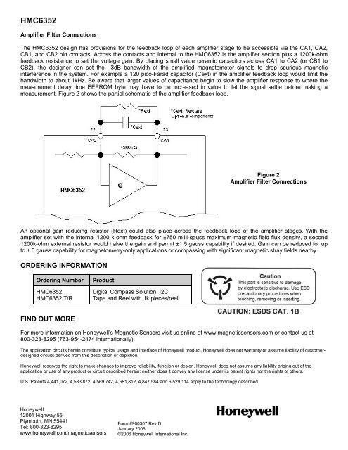
<strong>HMC6352</strong>Amplifier Filter ConnectionsThe <strong>HMC6352</strong> design has provisions for the feedback loop of each amplifier stage to be accessible via the CA1, CA2,CB1, and CB2 pin contacts. Across the contacts and internal to the <strong>HMC6352</strong> is the amplifier section plus a 1200k-ohmfeedback resistance to set the voltage gain. By placing small value ceramic capacitors across CA1 to CA2 (or CB1 toCB2), the designer can set the –3dB bandwidth of the amplified magnetometer signals to drop spurious magneticinterference in the system. For example a 120 pico-Farad capacitor (Cext) in the amplifier feedback loop would limit thebandwidth to about 1kHz. Be aware that larger values of capacitance begin to slow the amplifier response to where themeasurement delay time EEPROM byte may have to be increased in value to let the signal settle before making ameasurement. Figure 2 shows the partial schematic of the amplifier feedback loop.Figure 2Amplifier Filter ConnectionsAn optional gain reducing resistor (Rext) could also place across the feedback loop of the amplifier stages. With theamplifier set with the internal 1200 k-ohm feedback for ±750 milli-gauss maximum magnetic field flux density, a second1200k-ohm external resistor would halve the gain and permit ±1.5 gauss capability if desired. Gain can be reduced for upto ± 6 gauss capability for magnetometry-only applications or compassing with significant magnetic stray fields nearby.ORDERING INFORMATIONOrdering Number<strong>HMC6352</strong><strong>HMC6352</strong> T/RProduct<strong>Digital</strong> <strong>Compass</strong> <strong>Solution</strong>, I2CTape and Reel with 1k pieces/reelFIND OUT MOREFor more information on Honeywell’s Magnetic Sensors visit us online at www.magneticsensors.com or contact us at800-323-8295 (763-954-2474 internationally).The application circuits herein constitute typical usage and interface of Honeywell product. Honeywell does not warranty or assume liability of customerdesignedcircuits derived from this description or depiction.Honeywell reserves the right to make changes to improve reliability, function or design. Honeywell does not assume any liability arising out of theapplication or use of any product or circuit described herein; neither does it convey any license under its patent rights nor the rights of others.U.S. Patents 4,441,072, 4,533,872, 4,569,742, 4,681,812, 4,847,584 and 6,529,114 apply to the technology describedHoneywell12001 Highway 55Plymouth, MN 55441Form #900307 Rev DTel: 800-323-8295January 2006www.honeywell.com/magneticsensors13©2006 Honeywell International Inc.