Digital Compass Solution HMC6352
Digital Compass Solution HMC6352
Digital Compass Solution HMC6352
Create successful ePaper yourself
Turn your PDF publications into a flip-book with our unique Google optimized e-Paper software.
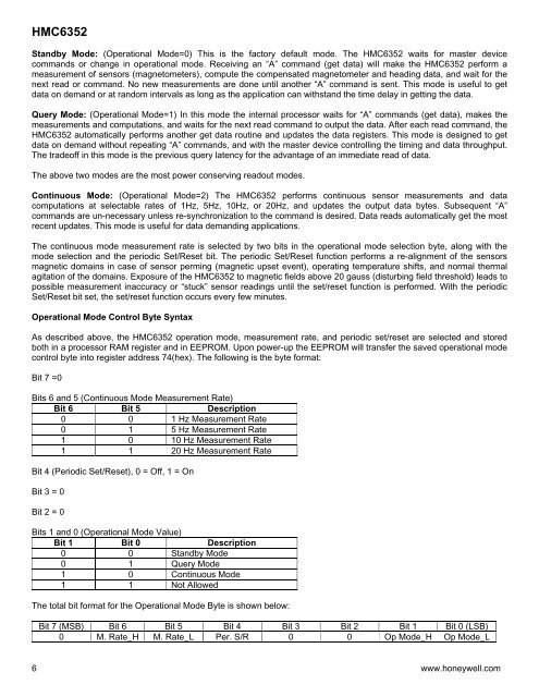
<strong>HMC6352</strong>Standby Mode: (Operational Mode=0) This is the factory default mode. The <strong>HMC6352</strong> waits for master devicecommands or change in operational mode. Receiving an “A” command (get data) will make the <strong>HMC6352</strong> perform ameasurement of sensors (magnetometers), compute the compensated magnetometer and heading data, and wait for thenext read or command. No new measurements are done until another “A” command is sent. This mode is useful to getdata on demand or at random intervals as long as the application can withstand the time delay in getting the data.Query Mode: (Operational Mode=1) In this mode the internal processor waits for “A” commands (get data), makes themeasurements and computations, and waits for the next read command to output the data. After each read command, the<strong>HMC6352</strong> automatically performs another get data routine and updates the data registers. This mode is designed to getdata on demand without repeating “A” commands, and with the master device controlling the timing and data throughput.The tradeoff in this mode is the previous query latency for the advantage of an immediate read of data.The above two modes are the most power conserving readout modes.Continuous Mode: (Operational Mode=2) The <strong>HMC6352</strong> performs continuous sensor measurements and datacomputations at selectable rates of 1Hz, 5Hz, 10Hz, or 20Hz, and updates the output data bytes. Subsequent “A”commands are un-necessary unless re-synchronization to the command is desired. Data reads automatically get the mostrecent updates. This mode is useful for data demanding applications.The continuous mode measurement rate is selected by two bits in the operational mode selection byte, along with themode selection and the periodic Set/Reset bit. The periodic Set/Reset function performs a re-alignment of the sensorsmagnetic domains in case of sensor perming (magnetic upset event), operating temperature shifts, and normal thermalagitation of the domains. Exposure of the <strong>HMC6352</strong> to magnetic fields above 20 gauss (disturbing field threshold) leads topossible measurement inaccuracy or “stuck” sensor readings until the set/reset function is performed. With the periodicSet/Reset bit set, the set/reset function occurs every few minutes.Operational Mode Control Byte SyntaxAs described above, the <strong>HMC6352</strong> operation mode, measurement rate, and periodic set/reset are selected and storedboth in a processor RAM register and in EEPROM. Upon power-up the EEPROM will transfer the saved operational modecontrol byte into register address 74(hex). The following is the byte format:Bit 7 =0Bits 6 and 5 (Continuous Mode Measurement Rate)Bit 6 Bit 5 Description0 0 1 Hz Measurement Rate0 1 5 Hz Measurement Rate1 0 10 Hz Measurement Rate1 1 20 Hz Measurement RateBit 4 (Periodic Set/Reset), 0 = Off, 1 = OnBit 3 = 0Bit 2 = 0Bits 1 and 0 (Operational Mode Value)Bit 1 Bit 0 Description0 0 Standby Mode0 1 Query Mode1 0 Continuous Mode1 1 Not AllowedThe total bit format for the Operational Mode Byte is shown below:Bit 7 (MSB) Bit 6 Bit 5 Bit 4 Bit 3 Bit 2 Bit 1 Bit 0 (LSB)0 M. Rate_H M. Rate_L Per. S/R 0 0 Op Mode_H Op Mode_L6 www.honeywell.com


