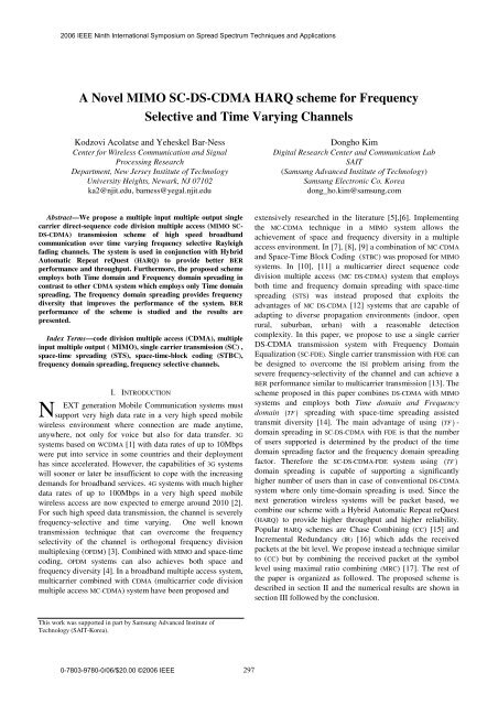
A Novel MIMO SC-DS-CDMA HARQ scheme for Frequency ...
A Novel MIMO SC-DS-CDMA HARQ scheme for Frequency ...
A Novel MIMO SC-DS-CDMA HARQ scheme for Frequency ...
- No tags were found...

Create successful ePaper yourself
Turn your PDF publications into a flip-book with our unique Google optimized e-Paper software.
achieve the maximum frequency diversity, the symbols ofTXjl ,repeated Q -times in the frequency domain mustexperience independent fading. For that to happen, thefrequency spacing between the repeated symbols must behigher than the coherence bandwidth of the channelBcoh≈ 1 τmwhere τmthe delay spread of the channel is. Theabove condition is satisfied if NTc≥ 1 τmthat is N ≥ Tc τm. Alsoin order to guarantee that each subcarrier experience flatfading, we must have Tc ≥ τm. There<strong>for</strong>e the chip duration T cmust satisfy the conditionτ ≤T≤ Nτ(8)m c mThe total system bandwidth B= ( NQ+Δ) Tcmust also be lessthan the available bandwidth B o, i.e.( NQ +Δ) Tc ≤ Bo(9)So the frequency domain spreading is limited by the availablebandwidth B .i.e.oQ≤( T B −Δ ) N(10)coLet Yr ⎡Yr,0 , , Yr, G−1vector arerl ,= ⎣ ⋯ ⎤ ⎦ be the NQ× G matrix whose columnY of (12) ; it is given by:T ∗ T T ∗ TYr = H ⎡r1⎣S1Qc1 − S2Q c ⎤ ⎡ ⎤2⎦ + Hr2 ⎣S2Qc1 + S1 Qc2⎦+ W (14)rwhere Wr = ⎡ ⎣ Wr,0 , ⋯ , Wr, G−1⎤ ⎦ . By multiplying (14) by c 1and thenby c2following conjugation, we get respectively:Z = H S + H S + Wc (15)r1 r1 1Q r2 2Q r 1Z = H S − H S + W c (16)∗ * ∗*r2 r2 1Q r1 2Q r 2where Zr1 = Ycr 1and Zr2 = Ycr 2(noting that c 2is real). Eq (15)and (16) can be rewritten as:Z 1r1 = ( Δr1S1+ Δr2S2)+ Wrc 1(17)Q∗ 1 ∗ ∗ ∗Zr2 = ( Δr1S1− Δr2S2)+ Wrc 2(18)QAt the receive antenna r , the CP are first removed (Fig. 2) andthe remaining received chip-blocks corresponding to theTtransmitted sub-blocks xjl ,are applied to an NQ -PointFFT block to yield:⌢ ⌢Yrl ,= Hr1X1, l+ Hr2 X2, l+ Wrl ,, l = 0, ⋯ , G−1(11)where Hrjis a NQ × NQ diagonal matrix whose NQ diagonalelements (the n th and ( n+ mN) th elements where n= 1, ⋯ , N andm= 1, ⋯ , Q are uncorrelated due to the condition in (8) ) are thefrequency response of the channel gain from the j th transmitthantenna to the r receive , X ⌢ jl ,is an NQ × 1 vector given in (5) ,Wrl ,is an NQ × 1 vector of the NQ -Point FFT of the channelnoise at the receive antenna r front end and Y rl ,is anNQ × 1 vector of the frequency domain received signal. Using(1) and (2) , (11) can be written as:Y = H ⎡⎣c () l S − c () l S ⎤⎦ + H ⎡⎣c () l S + c () l S ⎤⎦ + W(12)where∗∗rl , r1 1 1Q 2 2Q r2 1 2Q 2 1 Q rl ,1 T TTjQ= ⎡j jQ⎣ ⋯ ⎤ ⎦Q−timesS S S(13)Tis a NQ × 1 vector and Sj= ⎡ ⎣ Sj1⋯ S ⎤jN ⎦ is a N × 1 vector of N -TPoint FFT of sj= ⎡ ⎣ sj,1 ⋯ s ⎤j,N ⎦ . and cj() l is a scalar.(1) (2) ( Q)Twhere Δrj = [ Hrj Hrj ⋯ Hrj] is of size NQ× N and H( q)rjis aN× N diagonal matrix with diagonal elements the ( q− 1) N + 1 tothe qN diagonal elements of Hrj. The factor 1 Q in (17)and (18) come from (13).Combining (17) and (18) into one column vector we get:where1 ⎛Δr1 Δ ⎞r2Δr= * *Q ⎜⎟⎝Δr2 − Δr1⎠TTT⎡∗⎡ ⎤r r1 1, ⎡ ⎤ ⎤r2 2Zr = Δr S + Wr(19), ⎡1;2T ∗TS = ⎣ S S ⎤ ⎦ , Zr = ⎡ ⎣ Zr1,Z ⎤r2⎦W = ⎢ ⎣ ⎣ W c ⎦ ⎣ W c ⎦ ⎥ ⎦and Z is of size 2NQ × 1rConsidering theMRreceive antennas we get:Z = ΔS + W (20)Twhere , , TTTZ= ⎡ ⎣Z ⎤1⋯ ZMR ⎦ , , , TTW= ⎡ ⎣W ⎤1⋯ WMR ⎦ are of size 2MRNQ×1Tand , , TTΔ= ⎡ ⎣Δ ⎤1⋯ ΔMR ⎦HIt is easily shown that Δ Δ is diagonal matrix whichcompletely decouple the transmitted vectors S1and S2.T299
The minimum mean square estimation (MMSE) of S is givenby:ˆ 1( )SNRH−1HSmmse= Δ Δ + I2NΔ Z (21)We then take the N -Point IFFT of (21) to obtain the decisionT Tstatistics sˆ [ ˆ ˆmmse= s1, s2]mmse. Note that zero-<strong>for</strong>cing detection canHalso be used which gives similar results as the MMSE as Δ Δ isa diagonal matrix.The two received blocks s ˆT1and sˆT2are multiplexed to <strong>for</strong>mone block and fed to the viterbi decoder; the CRC is checkedin the packet <strong>for</strong> error. If the is no error the packet is acceptedand a positive Acknowledgement (ACK) is sent to thetransmitter otherwise the receiver send a negativeAcknowledgement (NACK). The transmitter then resends thepacket exactly as described above. The received data blocksare combined to the previous one (symbol level combining)using the pre-combining <strong>scheme</strong> of [17]. After R transmissions,the decision statistics are given by:R−1R() i H () i 1 ⎞ () i H () i∑2Ni= 1 SNR⎟ ∑i=1S ˆ ⎛mmse= ⎜ +⎝Δ Δ I ⎠Δ Z (22)III. NUMERICAL RESULTSThe parameters of the simulated system are chosen asfollowed:• 2× 2 <strong>MIMO</strong> system,• Number of symbols per block per antenna : N = 128• Length of cyclic prefix : Δ= 18• Spreading Factor : 32 ( Walsh Hadamard codes)The modulation on each block is QPSK. The multipath modelis selected to be a Rayleigh fading model with anexponentially decaying power profile. The channel is specifiedby the root mean square (rms) delay spread of the tap weights.and assumed quasi-static. The impulse response of the channelis composed of complex samples with random uni<strong>for</strong>mlydistributed phase and Rayleigh distributed magnitude withaverage power decaying exponentially. The k-th path of eachsub-channel is given by:α = N(0, σ ) + jN(0, σ )(23)1 2 1 2k 2 k 2 kk2 2Where σk σ0e −1= andτrms2 −rmsσ0= 1− e ; τ τrmsis the root meansquare delay spread of the channel normalized to the samplingrate. The maximal number of taps is L is chosen such that thedynamic range (the difference between the power of the lasttap and the first tap) is 20dB i.e. L ≥ 4.6τrms.In our simulation τrms= 3 and L is set to 16. As alreadydescribed above, the channel is very dispersive in the timedomain (frequency selective channel). Fig. 3 shows the BERper<strong>for</strong>mance of the proposed <strong>MIMO</strong>-<strong>SC</strong>-<strong>DS</strong>-<strong>CDMA</strong>-<strong>HARQ</strong> <strong>scheme</strong><strong>for</strong> one transmission ( R = 1)and Q = 1, 2, 3 which shows thefrequency diversity gain. Fig. 4 shows the per<strong>for</strong>mance afterR = 1, 2, 3 transmissions with MMSE <strong>for</strong> Q = 1, 2, 3 . We can seethe frequency diversity gain due the zeros insertion and the<strong>HARQ</strong> gain due to retransmission and symbol level combining.In Fig. 5 we compared the BER per<strong>for</strong>mance of the proposed<strong>scheme</strong> <strong>for</strong> one transmission ( R = 1)and Q = 1, 2 with the <strong>MIMO</strong>space-frequency block coding (SFBC) <strong>scheme</strong> of [4] whereAlamouti space-time block coding is applied in the frequencydomain. The result shows that the proposed <strong>scheme</strong>outper<strong>for</strong>ms the conventional <strong>MIMO</strong>-OFDM SFBC. Note that inthis comparison the system bandwidth <strong>for</strong> both <strong>scheme</strong> is thesame when Q = 2 (one time repetition in the frequencydomain) in our <strong>scheme</strong>. We also note that as the number oftransmissions R increases the frequency diversity gain is lesspronounced which suggests, adaptively reducing Q at laterretransmission. The adaptive approach and the multi-user casewill be presented in another paper.IV. CONCLUSIONIn this paper, a joint FDE, antenna diversity through spacetime-blockcoding combining and employing time andfrequency domain spreading was presented <strong>for</strong> a single user<strong>MIMO</strong> <strong>SC</strong>-<strong>DS</strong>-<strong>CDMA</strong> system in a frequency selective Rayleighfading Channel. The BER per<strong>for</strong>mance with <strong>HARQ</strong> is presented.<strong>Frequency</strong> diversity gain is obtained though it is limited by thetotal available bandwidth. The main contribution of this workis the use of single carrier transmission combined withfrequency domain spreading (frequency diversity gain) andspace-time block coding in a <strong>MIMO</strong> <strong>DS</strong>-<strong>CDMA</strong> system. Systemper<strong>for</strong>mance with <strong>HARQ</strong> and different level of frequencydiversity is examined. Per<strong>for</strong>mance advantage of the proposed<strong>scheme</strong> on the regular <strong>MIMO</strong>-SFBC with comparable bandwidthis also presented. This work currently is being extended tomulti-user case where the effect of the number of users and thespreading factor on the per<strong>for</strong>mance of the system are studied.REFERENCES[1] F. Adachi, M. Sawahashi and H. Suda, “Wideband <strong>DS</strong>-<strong>CDMA</strong> <strong>for</strong> nextgeneration Mobile Communications Systems,” IEEE Comm. Mag., Vol36, Sept 1998, pp 56-69[2] Y. Kim et al., “Beyond 3G : Vision, Requirement and EnablingTechnologies,” IEEE Comm. Mag., Vol 41, March 2003 , pp 120-124[3] Lajos Hanzo, M. Münster, B.J. Choi, Thomas Keller, “OFDM and MC-<strong>CDMA</strong> <strong>for</strong> Broadband Multi-User Communications, WLANs andBroadcasting”, John Wiley & Sons, 2003[4] K. F. Lee , D.B. Williams, “A Space-<strong>Frequency</strong> Transmitter DiversityTechnique <strong>for</strong> OFDM Systems,” IEEE GLOBECOM, San Francisco,CA, Nov. 2000, pp. 1473-1477[5] Bar-Ness Y., Visser M, “Adaptive Reduced Complexity Multicarrier<strong>CDMA</strong>(MC-<strong>CDMA</strong>) structure <strong>for</strong> Downlink PCS”, EuropeanTransaction on Telecommunications, Vol. 10, no 4, pp 437-444,July/August 1999.[6] Tan M., Zong P., Bar-Ness Y.,”Multi-Rate Access Schemes <strong>for</strong> MC-<strong>CDMA</strong>”, Wireless Personnal Comm., Vol. 27, no 2, pp Nov. 2003300
[7] V. Le Nir, M. Hélard, R. Legouable, “Space-Time Block CodingApplied to Turbo Coded Multicarrier <strong>CDMA</strong>,” Vehicular TechnologyConference, Jeju, South Korea, 22-25 April 2003.[8] F. Adachi, D. Garg, S. Takaoka, K. Takeda, “ Broadband <strong>CDMA</strong>Techniques,” IEEE Wireless Comm. , April 2005[9] D. Garg and F. Adachi , “Joint Space-Time Transmit Diversity andMinimum Mean Square Error Equalization <strong>for</strong> MC-<strong>CDMA</strong> withAntenna Diversity Reception,” IEICE Trans. Comm. , Vol E87-B, no.4, April 2004, pp 849-857[10] Lie-Liang Yang; Hanzo, L. “Broadband MC <strong>DS</strong>-<strong>CDMA</strong> using spacetimeand frequency spreading”, VTC 2002-Fall, Volume 3, 24-28Sept. 2002 Page(s):1632 - 1636 vol.3[11] Jia Tang and Xi Zhang "A <strong>Novel</strong> Complex-Modulation Based Space-Time Spreading Scheme with More Than Two Transmit Antennas <strong>for</strong>MC-<strong>DS</strong>-<strong>CDMA</strong> Systems", The 38th Conference on In<strong>for</strong>mationSciences and Systems, Princeton University, Princeton, NJ, USA,March 17--19, 2004[12] Yang, L. L. and Hanzo, L. “ Multicarrier <strong>DS</strong>-<strong>CDMA</strong>: A MultipleAccess Scheme <strong>for</strong> Ubiquitous Broadband Wireless Communications”2003. IEEE Communications Magazine :pp. 116-124[13] D. Falconer, S.L. Ariyavisitakul, A. Benyamin-Seeyar, and B. Eidson,“ <strong>Frequency</strong> domain equalization <strong>for</strong> single carrier broadband wirelesssystems,” IEEE Comm. Mag., vol 40, no4, pp58-66, April 2002[14] B. Hochwald, T.L. Marzetta, and C. B. Papadias,” A transmitterdiversity <strong>scheme</strong> <strong>for</strong> wideband <strong>CDMA</strong> systems based on space-timespreading”, IEEE JSAC, Vol. 19, no. 1, pp. 48-60, Jan 2001[15] D. Chase, “Code Combining – A Maximum Likelihood DecodingApproach <strong>for</strong> Combining an Arbitrary Number of Noisy Packets,”IEEE Trans. Comm. , Vol COM-33, May 1995, pp 385-393[16] J. Hagenauer, “ Rate-Compatible Punctured Convolutional Codes(RCPC Codes) and Their Application,” IEEE Trans. Comm , Vol36, April 1998, pp 389-400[17] Eko N. Onggosanusi, Anand G. Dabak, Yan Hui, Gibong Jeong, “Hybrid ARQ transmission and combining <strong>for</strong> <strong>MIMO</strong> systems “ICC 2003 - IEEE International Conference on Communications,vol. 26, no. 1, May 2003 pp. 3205-3209J.BER10 -110 -210 -3DatarR XRemoveCP1S-P 2NS-Ps 1,1s 2,1s 1,ks 2,ks 1, Ns 2,Nc1 = [ c1(0), ⋯ , c1( G −1)]c2 = [ c2(0), ⋯, c2( G −1)]y ⋯ ySTSSTSSTSr,0 r, G−1x 1,1x 2,1x 1,kx 2,kx 1, Nx 2,NNQ-PointFFTY ⋯ Yr,0 r, G−1Interleaving and<strong>Frequency</strong>-domainSpreadingby zeros insertion inTime-domainInterleaving and<strong>Frequency</strong>-domainSpreadingby zeros insertion inTime-domainFig. 1 Transmitter StructureDe-spreadingFig. 2 Receiver Structure at the r-th receive antenna⊗c 1c 2⊗P-SP-<strong>SC</strong>ombiner&FDE10 0 1/2 Conv.; QPSK MMSE; Channel length L = 16CPCP1T XN-PointIFFT2T XQ=1Q=2Q=3ŝ 1ŝ 210 -410 -11/2 Conv. QPSK MMSE L=16Proposed Q=1Proposed Q=2SFBC of [4]10 -50 2 4 6 8 10 12 14 16Eb/NoFig. 3 BER Per<strong>for</strong>mance <strong>for</strong> Q=1, 2, 3BER10 0 EbNo10 -210 -310 -4BER1/2 Conv.; QPSK MMSE; Channel length L = 1610 010 -110 -2Q=1 R=1Q=1 R=2Q=1 R=3Q=2 R=1Q=2 R=2Q=2 R=3Q=3 R=1Q=3 R=2Q=3 R=310 -310 -56 8 10 12 14 16 18 20Fig. 5 BER comparison with <strong>MIMO</strong>-OFDM SFBC <strong>for</strong> R=1transmission10 -410 -50 2 4 6 8 10 12 14 16Eb/NoFig. 4 BER Per<strong>for</strong>mance <strong>for</strong> Q=1, 2, 3 and R=1,2,3transmissions301