endace daG TIme-STamPInG wHITePaPeR
endace daG TIme-STamPInG wHITePaPeR
endace daG TIme-STamPInG wHITePaPeR

Create successful ePaper yourself
Turn your PDF publications into a flip-book with our unique Google optimized e-Paper software.
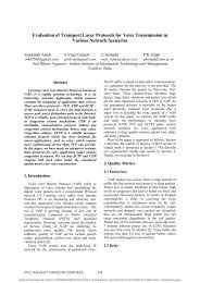
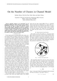
WHITEPAPERwww.<strong>endace</strong>.comenquiries@<strong>endace</strong>.comENDACE DAGTIME-STAMPING WHITEPAPERStephen Donnelly, PhD Endace Technology LtdIntroductionMany commercially vital network tasks such as trafficengineering, Quality-Of-Service (QOS) measurement, and SLAverification require the ability to accurately measure networklatency, flow bandwidths, and packet delays. All of thesemeasurements in turn rely on the ability to accurately measurethe arrival time of packets at a point in the network.Endace Measurement Systems builds dedicated networkmeasurement cards, with hardware especially designed toprovide very high quality packet time-stamps to address theseneeds. Why build custom hardware? Surely a modern server PCwith a network interface card (NIC) card can do just as well?There are unfortunately several problems with this approach.First this presupposes that a card is available for the networkphysical layer in question. While this may be true for commonLAN links, WAN NICs may be less accessible. Secondly and moreimportantly, NICs are not designed with network measurementas their foremost priority.NICs are seldom designed to operate on a link at very highloading, providing all of the network data to the PC. NICsare designed to send and receive packets at moderate rates,sufficient for the services or clients running on a singlecomputer. DAG cards are designed with sufficient performanceto allow the measurement of data from even fully saturatednetwork links.A NIC is also not well suited to accurately recording the arrivaltimes of packets on a network link. NICs generally do nottime-stamp packet arrivals, as this is not a critical task for anetwork interface card. In order to timestamp a packet arrivalusing a NIC, the host PC must capture the time-stamp usingits own clock, some time after the packet has arrived, the NIChas delivered the packet to the PC, and notified its driver that apacket has arrived.This notification is typically in the form of an interrupt. Once apacket has arrived, been checked, and copied to the PC, the NICwill interrupt the PC.DAGTIME-STAMPIPPMWIRE-EXIT-TIMENICTIME-STAMPPREAMBLE SFD MAC HEADER IP PACKETCRCNIC PACKETPROCESSING COPYINTERRUPTLATENCYCODETIMEPREAMBLESTARTSPREAMBLEENDIP PACKETSTARTSIP PACKETENDSINTERRUPTHOST PCSYSTEM TIMEREADMAC FRAMESTARTSMAC FRAMEENDSINTERRUPTSERVICEDEDM12-205v2
ENDACE DAGTIME-STAMPING WHITEPAPER – c o n t ’dWhen the host CPU becomes free, it will service this interrupt,allowing the NIC device driver to discover that a packet has beenreceived so that a timestamp may be recorded. The delay betweenthe interrupt being signaled and processed is called the interruptlatency. This latency is typically low, only a microsecond or so, butdepending on the host PC’s hardware and what kind of processingit is doing, the latency may occasionally be as high as tens ofmilliseconds, and there is no way to know when this occurs.This can lead to potentially large and unknown errors in timestampaccuracy.A further problem with interrupt based signaling is that inorder to reduce the number of interrupts generated, and henceload on the host, some NICs do not generate always generateone interrupt per packet received. By generating an interruptonly after several packets have arrived, the interrupt rate isreduced, but only one time-stamp is available to be appliedto several packets, which will appear to have arrived almostsimultaneously!The final problems with this approach are concerned with theclock used to capture the time-stamps themselves, the hostPC’s clock. One issue concerns precision. The system clock usedto record packet timestamps typically provides microsecondresolution. This is already becoming insufficient as network linkspeeds increase. A minimum length packet on a Gigabit Ethernetnetwork (64 Bytes) arrives in just 0.512 microseconds.The second issue is to do with accuracy. The clock in a PCtoday is based on an inexpensive quartz crystal. The crystalis cut in such a way that it resonates electrically at a specificfrequency. This is then used to generate a clock for the machine.The exact frequency however varies between crystals due tomanufacturing, and the frequency of a specific crystal varieswith temperature and applied voltage. These inaccuracies don’tmatter to the operation of the computer, and are generally lessthan 100 parts per million (ppm), which is equivalent to a fewseconds lost or gained per day.Packet delay through a RouterEvery crystal oscillates at a slightly different frequency, whichalso changes with temperature, so the clocks in two PCs even ifinitially synchronised will tell different times after a while. Thismakes the comparison of time-stamps recorded by differentcomputers difficult in practise, as the difference between theclocks may not be known.Without the ability to accurately time-stamp packet arrivalsat high resolution, and compare those time-stamps betweendifferent measurement points, accurate measures of networkmetrics such as packet delay, jitter, and flow bandwidths cannotbe made.Endace’s solution to the time-stamping problem is to builddedicated network measurement cards that record a highresolution time-stamp for each arriving packet in hardware,from a clock that can be continually synchronised to an externalstandard.What is Time?The exact nature of time itself still eludes both physicists andphilosophers; however we all have an intuitive understanding ofit from our own experience.We perceive time as flowing constantly from future to past, andmeasure it in equal periods. The base unit for measuring time isthe second, defined by the International System (SI):“The second is the duration of 9 192 631 770 periods of theradiation corresponding to the transition between the twohyperfine levels of the ground state of the cesium 133 atom.”This precise definition hardly affects our daily lives however.Most countries accept Coordinated Universal Time (UTC) as thebasis of their official time.UTC is calculated by the Bureau International des Poids etMeasures (BIPM) in Sevres, France. The BIPM averages datacollected from more than 200 atomic time and frequencystandards located at about 50 laboratories, including theNational Institute of Standards and Technology (NIST). As aresult of this averaging, the BIPM generates two time scales,International Atomic Time (TAI), and Coordinated Universal Time(UTC). These time scales realize the SI second as closely aspossible.
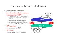
ENDACE DAGTIME-STAMPING WHITEPAPER – c o n t ’dUTC runs at the same frequency as TAI, but includes additionalleap seconds which are added at a rate of approximately 8 every10 years. Leap seconds are to keep UTC within ±0.9 s of an oldertime scale called UT1, which is based on the rotational rate ofthe Earth.What is GPS?Referred to as GPS, the Global Positioning System is a satellitebased navigation system built by the American Department ofDefense. The system is based on a set of at least 24 satellitesin earth orbit. Each satellite contains an atomic clock, andbroadcasts the time of its clock by radio. Small receivers canlisten to the signals from multiple satellites, and determine theexact time. By measuring the time taken for the signals to reachthe receiver from each satellite the distance from each can befound. By triangulation it is then possible to determine theirown position relative to the satellites. By predicting where thesatellites are in their orbit, the position of the receiver on (orabove) the earth can be determined very accurately.What is CDMA?CDMA stands for Code Division Multiple Access, and is aparticular new type of cellular telephone service. The CDMAsystem requires that all of the elements in the system are tightlysynchronised, so that they can transmit in allocated time slots.In order to achieve this synchronisation, each CDMA base stationincludes a GPS receiver, with which to tell the time. This time isthen broadcast as part of the base stations control signals to allCDMA handsets.Since each CDMA receiver can accurately tell the time based onthe base station’s transmissions, a CDMA receiver can be used inplace of a GPS receiver in order to provide a reference for clocksynchronisation.The advantage of CDMA over using GPS directly is that the CDMAradio signals are at a lower frequency, and much stronger. Thisallows them to easily pass through building, whereas the faintGPS signals require that an antenna be mounted outside with aclear view of the sky. Installing this kind of infrastructure can beexpensive and time consuming, requiring roof access and cablepulls. A CMDA receiver can use a simple antenna within even anoisy machine room. As the receiver does not transmit, it is notvisible to the network, and does not require a subscription orattract any charges.The Global Positioning System (GPS) operated by the US Departmentof Defense uses 24 satellites in low Earth orbit, each with highlyaccurate atomic clocks onboardHow does GPS help with timekeeping? In order to produceaccurate packet time-stamps, we need a clock that is bothaccurate and synchronised. An accurate clock runs at a knownrate. Two clocks in separate locations that are synchronised willtell the same time if read simultaneously.Because GPS broadcasts the current time based on atomicclocks, GPS receivers can also be used as very accurate clocks,synchronised to UTC within ±100 nanoseconds. A GPS receivercan then be used to synchronize time-stamping clocks anywherein the world with atomic accuracy.All Endace DAG network measurement cards come withconnectors allowing a GPS receiver to be connected to provideclock synchronization.The disadvantage of CDMA for timing is that although it is basedon accurate GPS time, there is an unknown distance betweenthe CDMA receiver and the base station. This unknown distancetranslates to an unknown delay in the time data being sent fromthe base station and being received by the CDMA receiver. Thismeans that a CDMA connected clock will have a small unknownoffset from UTC. The offset will remain constant, unless theCDMA receiver switches base stations. This may happen dueto maintenance or interference, and the change of distance tothe new base station would mean that the clock’s offset wouldchange also.
ENDACE DAGTIME-STAMPING WHITEPAPER – c o n t ’dWhat is NTP?The Network Time Protocol (NTP) can be used to synchronise theclock of a client computer to another server or a reference suchas a GPS or CDMA receiver. It is a hierarchical system, where thetop level NTP servers which have reference clock directly attachedare called Stratum 1 servers. Time is distributed from Stratum 1servers through a tree of servers of increasing stratum until theclient is reached. It typically offers synchronisation of a client PCto UTC within a millisecond over a LAN, and up to a few tens ofmilliseconds over a WAN such as the Internet.In NTP, a client sends a request to a server, asking what timeit is. The server responds with the current time, and the clientmeasures the time that the transaction took. The client dividesthe transaction time in half, and adds this to the current timesupplied by the server. This is to account for the fact that thereply from the server will take some time to reach the client.Unfortunately the calculation assumes that the delay betweenthe client and the server is symmetrical. As this is often notthe case, it explains why NTP performance is worse over WANnetworks where asymmetrical delay is more common. Theclient will typically query more than one server, and choose the‘best’ server to use each time, carefully rejecting outliers andmeasuring the stability of each one.Global synchronization of DAG cards via GPS enables one-waymeasurements with astonishing precisionOn a Stratum 1 server, that is one with an external referencedirectly attached, the accuracy of the local system clock canbe much better, within 100 microseconds of UTC. In this caseperformance is constrained by factors such as interrupt latency,and the implementation of the operating system clock. The clockmay still be adjusted stepwise rather than completely smoothlyhowever.What is the DUCK?The DAG Universal Clock Kit (DUCK) is Endace’s solution toproviding per packet time-stamps that are both high resolutionand capable of accurate synchronisation to UTC. It consists of acrystal oscillator, synchronization connector, and FPGA firmwareon each DAG card, along with synchronization code in the devicedriver and configuration utilities.When a packet is received by a DAG card, the DUCK time-stampsthe beginning of the packet arrival in hardware. This is differentfrom NIC based time-stamping, which occurs in the host PCsometime after the packet has arrived, approximating a timestampfor the end of the packet.Time-stamp FormatThe time-stamp format that the DUCK produces is a littledifferent to those commonly encountered. Unix has two basicways of representing time, both of which are structures. TheUnix struct timeval consists of a 32-bit count of seconds sincemidnight on the first of January, 1970. This is what is used totell the ‘wallclock’ time and date. The second 32-bit number isa count of microseconds since the start of the current second.The Operating system does not necessary update this value everymicrosecond, this is just the resolution of the time format.The second Unix time representation is the struct timespec,which consists of a 32-bit seconds count as for a struct timeval,but the other 32-bit value is expressed in nanoseconds ratherthan seconds. This representation allows for a resolution of onenanosecond, but many applications use only struct timeval.Once the NTP daemon on the client has an estimate of thecurrent time, it needs to try to adjust the operating system’sclock to match. If the difference is too large, it may simplyrefuse. If the difference is a matter of seconds, it may simplychange the clock in one step, causing a discontinuity in time,and hence in time-stamps generated using the clock. If theclock is ‘close’ to being correct, then the NTP daemon will try toslightly speed up or retard the clock’s rate, so that the differencebetween it’s value and the estimatedUTC time will reduce. Thisis a slow process, and when the NTP daemon is started on ahost it may take several hours for the operating system clock toconverge to within a millisecond of UTC.
ENDACE DAGTIME-STAMPING WHITEPAPER – c o n t ’dThe DUCK represents time as a single 64-bit fixed point number,representing seconds since midnight on the first of January1970. The high 32-bits contain the integer number of seconds,while the lower 32-bits contain the binary fraction of thesecond. This allows an ultimate resolution of 2-32 seconds, orapproximately 233 picoseconds. Another advantage of the DUCKtimestamp format is that a difference between two timestampscan be found with a single 64-bit subtraction, it is not necessaryto check for overflows between the two halves of the structure asis needed when comparing Unix time structures.If at any time the Phase Error value exceeds the Threshold for 10or more seconds, the DUCK status changes to ‘unhealthy’, andwill return to the ‘healthy’ or synchronised state only once clocksynchronisation is restored.The utility ‘dagclock’ can be used to read the DUCK status andclear error counters at any time.Clock GenerationIn order to produce time-stamps of this format, the clock mustrun at a frequency that is a power of two. In DAG cards for lowdata rate network links, the frequency used is 16,777,216Hz,providing a clock resolution (tick) of approximately 60nanoseconds. For higher speed links a frequency of 67,107,864Hz is used for a resolution of approximately 15 ns. For thehighest speed links, 134,217,728 Hz is used, for a resolution ofapproximately 7.5 nsThese frequencies are generated by direct digital synthesis(DDS) from a crystal oscillator, based on a programmableratio. By measuring how many times the clock ticks per secondcompared to a reference, the driver can finely adjust the DDSprocess to alter the frequency generated, compensating forchanges in the crystal oscillator. These corrections when madewith an accurate reference allow both the frequency of the clockand the synchronisation of the clock to UTC to be accuratelymaintained.Clock SynchronisationIf the clock is running too quickly, more ticks than expectedwill be counted. If the clock is running too slowly, fewer thanexpected ticks will be counted.This difference is reported as the Frequency Error, measured inparts per billion. If the fractional part of the second is not zerowhen the reference signal is received, the DAG clock is offsetfrom the reference, and is not properly synchronized. This isreported as the Phase Error, measured in nanoseconds.When a reference clock is connected to a card, and the PhaseError is greater than the configurable Threshold (defaulting to596ns), the driver will emit warning messages to the systemlog. Once synchronised, the Frequency Error and Phase Errorvalues are typically less than ±2 ticks of the synthetic clock.When a reference clock is first connected, the DUCK may takeup to a minute to synchronise. As the DUCK clock is initialisedfrom the Operating System clock, the better synchronised thisis the faster the DUCK will converge to the correct time. For thisreason it is recommended that NTP is used to maintain looseclock accuracy on the host PC.The TDS-2 and TDS-6 Time Distribution Server modules allow asmany as 20 DAG cards to be synchronized to a single time referenceDUCK InputsThe DUCK can accept one of four inputs for its reference source.These are:1. rs422: A pulse from the synchronisation connector2. host: A signal from the host PC3. over: The DUCK clock overflowing between seconds4. aux: An auxiliary inputThe rs422 option allows the direct connection to the DAG cardof a RS-422 Pulse Per Second (PPS) signal from a GPS orCDMA receiver. This input is enabled by default. Endace offersthe TDS-2 (and TDS-6) Time Distribution Server which allowsthe connection of up to 20 DAG cards to a single GPS or CDMAreceiver, and provides signal level conversion.The host option is for testing purposes, while the over optionallows the DUCK to by synchronised to the PC’s operating systemclock. This can be useful if NTP is used to maintain the PC’sclock, but is not as accurate as a direct PPS connection. The auxoption is currently unused.
ENDACE DAGTIME-STAMPING WHITEPAPER – c o n t ’dWhat about different Link Layers?DAG cards are available for many link layer types, includingFast, Gigabit and 10 Gigabit Ethernet, T1/E1, DS3, SONET OC3c,OC12c, OC48c and OC192c (SDH STM-1c, STM-4c, STM-16c andSTM-64c). Different link layers, protocols and hardware deviceshave various impacts on the time-stamping process.Figure 4EndRun Technologies Præcis Ct time receivers derive theirtiming information from the GPS system indirectly, by receivingCDMA cellular telephone network signals. When used with DAGcards via a TDS-2, the recorded packet timestamps are typicallywithin 10 microseconds of UTC when the CDMA receiver islocked.EthernetIn Ethernet, each frame is preceded by typically 8 preamblebytes. Network devices such as hubs and switches are permittedto add or drop preamble characters as packets pass through. Thenumber of preamble bytes present on any particular packet isnot recorded. Ethernet also specifies a minimum time betweenpackets where the link must idle. This is called the Inter FrameGap (IFG). Both the preamble and IFG bytes should be accountedfor when calculating Inter-Packet Arrival times, link utilisation,or bandwidths.SONET/SDHIn SONET and SDH, a complex framing protocol is usedconsuming approximately 3% of the raw link bandwidth.The framing consists of Path Overhead (POH) and TransportOverhead (TOH). The framing overhead is not packet aligned somay occur within packets, increasing the time required for thepacket to be transmitted or received. It is not possible to tell ifoverhead has interrupted a particular packet. This uncertaintymust be accounted for when calculating Inter-Packet Arrivaltimes, link utilisation, or bandwidths.Figure 5Figure 5 shows the distribution of timestamp differences over24 hours when one DAG card is synchronized by GPS, and theother is synchronized by CDMA. We can see a larger differencebetween the two clocks, but the difference is within the 10microseconds specified. The timestamps recorded by the CDMAand GPS receivers have a mean difference of 2.36 microseconds,which represents the distance between the CDMA base stationand the receiver. The distance can be estimated from the delayas approximately 707m (2321’) in this case. In most urbanenvironments the distance to the base station will normally beless than 3.2km (2 miles).ATMATM cells are 53 bytes long on the network, comprising of a 4byte header, one byte header checksum, and 48 bytes of data.The header is tested against its checksum. If the checksummatches the cell is passed through with the checksumstripped leaving a 52 byte cell, if the checksum fails the cell isdiscarded. A cell length of 53 bytes should be used in bandwidthcalculations.Packet Over SONETPacket-Over-SONET (POS) uses a framing scheme called High-Level Data Link Control (HDLC). The HDLC framing processinvolves adding flags between frames, a CRC, and an end offrame sequence. HDLC also inserts characters into the frame to
ENDACE DAGTIME-STAMPING WHITEPAPER – c o n t ’descape any flag bytes that may be present in the payload. A DAGcard in POS mode strips the escape characters, and reports thenon-escaped length. The length of the frame on the wire may belonger than the reported length depending on how many escapesequences were removed. This difference can be calculated if theentire payload is available by counting the number of escapesthat would be necessary. If the payload is not all available (notall of the packet content was captured) then this uncertainty inlength will produce an uncertainty in Inter-Packet Arrival times,link utilisation and bandwidths.ReferencesDAG and TDS-2/TDS-6 User ManualsAvailable in the Endace software distribution, on the EndaceInstall CD and from http://www.<strong>endace</strong>.comThe National Institute of Standards and Technology,Time and Frequency Divisionhttp://www.boulder.nist.gov/timefreq/index.htmlExecutive Summary – Computer Network Time Synchronisation,Official NTP Documentationhttp://www.ntp.orgHigh Precision Timing in Passive Measurements of DataNetworksby Stephen Donnelly, the University of Waikatohttp://wand.cs.waikato.ac.nz/pubs.phpAcutime 2000 Synchronization Kit User GuideTrimble Navigation Limitedhttp://www.trimble.comPraecis Ct Network Time Source User ManualEndRun Technologieshttp://www.endruntechnologies.com©2007 Endace Technology Limited. All rights reserved. Endace, the Endace logo, Endace Accelerated ® , DAG, NinjaBox ® and NinjaProbe are trademarks or registered trademarks in New Zealand, orother countries, of Endace Technology Limited. All other product or service names are the property of their respective owners. Product and company names used are for identification purposes onlyand such use does not imply any agreement between Endace and any named company, or any sponsorship or endorsement by any named company. The information contained herein is subject tochange without notice. Nothing herein should be construed as a warranty and Endace shall not be liable for technical or editorial errors or omissions contained herein.