The Figure 990 butterfly valve has a split, wafertype body, features a ...
The Figure 990 butterfly valve has a split, wafertype body, features a ...
The Figure 990 butterfly valve has a split, wafertype body, features a ...

Create successful ePaper yourself
Turn your PDF publications into a flip-book with our unique Google optimized e-Paper software.
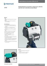
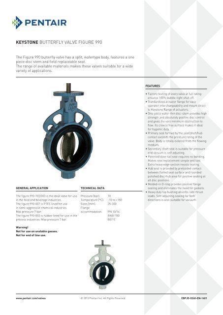
Keystone Butterfly Valve <strong>Figure</strong> <strong>990</strong><strong>The</strong> <strong>Figure</strong> <strong>990</strong> <strong>butterfly</strong> <strong>valve</strong> <strong>has</strong> a <strong>split</strong>, <strong>wafertype</strong> <strong>body</strong>, <strong>features</strong> a onepiece disc stem and field replaceable seat.<strong>The</strong> range of available materials makes these <strong>valve</strong>s suitable for a widevariety of applications.FeaturesGeneral application<strong>The</strong> figure <strong>990</strong>-102/003 is the ideal <strong>valve</strong> for usein the food and beverage industries.<strong>The</strong> figure <strong>990</strong>-007 is PTFE lined for usein semi-aggressive chemical industries.Max pressure 7 bar.<strong>The</strong> figure <strong>990</strong>-002 is rubber lined for use in theprocess industries. Max pressure 7 bar.Warning!Not for use on unstable gasses.Not for end of line use.Technical dataPressure (bar): 10Temperature (°C): -10 to +150Sizes (mm): 25-300Flangeaccommodation: PN 10/16ANSI 150BST’E’• Factory testing of every <strong>valve</strong> at full ratingensures 100% bubble-tight shut-off.• Standardized actuator flange for easyoperator interchangeability and mount directto Keystone Range of actuators.• One-piece wafer-thin disc-stem provides highstrength and absolutely positive disc controland gives the very minimum obstruction toflow. Its crevice free surface makes it idealfor hygienic duty.• Primary seal formed by the seat/shaft/hubcontact exceeds the pressure rating of the<strong>valve</strong>. Body is totally isolated from the flowingmedium.• Secondary shaft seal is suitable for pressureand vacuum is self adjusting.• Patented dove-tail seat requires no bonding.Makes seat replacement simple and fast.Extra heavy edge section resists tearing.• Hub seal is provided by preloaded contactbetween flatted seat surface and roundedpolished disc-hub area for positive sealing atall disc positions.• Molded-in O-ring provides positive flangesealing and eliminates the need for gaskets.• Heavy duty top bushing absorbs side thrustloads. Self-adjusting sealing for bothdirections is also suitable for vacuum.www.pentair.com/<strong>valve</strong>s© 2012 Pentair Inc. All Rights Reserved.EBPJD-0260-EN-1401
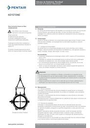
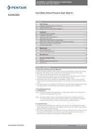
Keystone Butterfly Valve <strong>Figure</strong> <strong>990</strong>25-300 mmGF12D3C45QAYYB7E45°6Valve dimensions in mmSize A B C D E F YY Q Mass (kg)25 31 62 78 29 57 19 50 15 0.7040 45 82 95 30 57 19 67 35 1.1050 51 109 140 41 102 32 87 33 2.7065 64 129 152 45 102 32 98 48 3.7580 76 144 160 45 102 32 114 64 4.00100 102 164 178 51 102 32 146 90 5.50125 127 194 190 54 102 32 168 117 7.20150 146 220 203 54 102 32 197 138 8.50200 197 275 241 64 152 32 254 189 15.00250 248 330 273 64 152 32 305 241 20.00300 298 377 312 76 152 51 353 291 31.00Part name1. Bushing2. Shaft seal3. Upper <strong>body</strong>4. Seat5. Disc-stem6. Lower <strong>body</strong>7. Body screwsNotes1. Valve size shown is the 100 mm; other sizes showdifferent configurations. For information seeseparate data sheets.2. Q is the disc chordal dimension at face of <strong>valve</strong> fordisc clearance into pipe fitting or equipment.45°E PCDE JPCDKGFPFPGSizes 25-200 mmSizes 250-300 mmActuator flange dimensions in mmShaft dimensionsActuator flange dimensionsKeysizeNo. ofSize F G K J width x height E P PCD Hole ø holes25 19 9,53 6,35 - - 57 8 44,5 6.3 440 19 9,53 6,35 - - 57 8 44,5 6.3 450 32 14,28 9,5 - - 102 13 82,5 11.1 465 32 14,28 9,5 - - 102 13 82,5 11.1 480 32 14,28 9,5 - - 102 13 82,5 11.1 4100 32 15,88 11,10 - - 102 13 82,5 11.1 4125 32 19,05 12,70 - - 102 13 82,5 11.1 4150 32 19,05 12,70 - - 102 13 82,5 11.1 4200 32 22,20 15,88 - - 152 16 127,0 14.3 4250 32 28,58 - 25,40 6,35 x 6,35 152 16 127,0 14.3 4300 51 28,58 - 25,40 6,35 x 6,35 152 16 127,0 14.3 42
Keystone Butterfly Valve <strong>Figure</strong> <strong>990</strong>Valve dataK v valuesSize in mmDisc opening 25 40 50 65 80 100 125 150 200 250 30010° 0,4 0,9 1,7 2,6 3,4 5 9 15 21 33 4920° 1,7 4,3 7 10 14 25 38 52 95 155 22030° 4,3 9,5 16 22 33 54 86 120 220 340 51040° 6,9 16 26 38 57 95 160 220 380 610 86050° 11 26 43 60 95 150 240 340 590 950 146060° 17 40 69 95 150 240 390 550 950 1550 232070° 29 66 110 160 240 400 640 950 1550 2580 378080° 46 103 170 250 370 620 950 1380 2410 3960 585090° 52 120 320 430 590 960 1510 2000 3550 5800 846090° * 52 120 320 430 590 960 1510 2000 3550 5800 8460* Rubber covered discNote1. Rated K v = the volume of water in m 3 /hr that willpass through a given <strong>valve</strong> opening at a pressuredrop of 1 bar.Maximum allowable shaft torques in NmSize in mmShaft mat. 25 40 50 65 80 100 125 150 200 250 300SS 20 20 60 60 60 100 180 180 290 725 725Sizing torques in NmSize in mmΔP in bar 25 40 50 65 80 100 125 150 200 250 3001*3,5 6 10 20 25 30 45 62 89 150 230 3307 7 11 21 26 32 48 68 100 180 270 38010 8 12 23 27 35 52 74 110 200 300 4402*3,5 8 12 27 32 39 59 81 120 200 300 4207 9 13 28 33 42 62 87 130 220 330 47010 10 14 29 35 44 66 92 140 240 370 5303*3,5 10 14 32 38 47 71 97 144 240 360 5047 11 16 34 40 50 74 104 156 264 396 56410 12 17 36 42 53 79 110 168 288 444 6361* Application I2* Application II3* Application IIINotes1. Application I:Water, seawater, lubricating types ofhydrocarbons. Temp.: 0-80°C;Valve opens at least once a month.Application II:All other liquid applications and lubricatinggasses.Application III:Non lubricating and dry media.2. <strong>The</strong> charted maximum sizing operating torque isthe sum of all friction and resistance for openingand closing of the disc against the indicatedpressure differential.3. <strong>The</strong> effect of dynamic torque is not considered intabulation.4. In sizing operators it is not necessary to includesafety-factors.Dynamic torque factors F T for metric unitsSize in mmDisc opening 25 40 50 65 80 100 125 150 200 250 30010° 0,08 0,2 0,5 0,9 1,2 2,7 4,3 6,1 13 28 3920° 0,10 0,2 0,7 1,0 1,5 3,4 5,9 8,7 20 40 6130° 0,11 0,3 0,8 1,3 2,1 4,8 8,4 13 30 61 9540° 0,15 0,5 1,0 1,5 3,0 6,4 12 20 47 94 15350° 0,20 0,7 1,5 2,6 4,3 10 19 30 71 141 23060° 0,25 0,8 2,1 3,9 6,4 15 29 48 112 220 38070° 0,41 1,3 3,1 5,9 10 24 45 76 176 350 61080° 0,57 1,8 4,4 8,5 14 34 65 112 260 520 890Notes1. Dynamic operating torque formula:T D = F T x ΔPT D = Dynamic torque (Nm)ΔP = Pressure drop across disc air desired disc-opening (bar)F T = Dynamic torque factor (see table)2. <strong>The</strong> dynamic torque includes all frictional resistances.3. <strong>The</strong> dynamic torque is tending to close the disc.4. <strong>The</strong> charted maximum allowable torques are only applicable for standard type <strong>valve</strong>s.3