
Create successful ePaper yourself
Turn your PDF publications into a flip-book with our unique Google optimized e-Paper software.
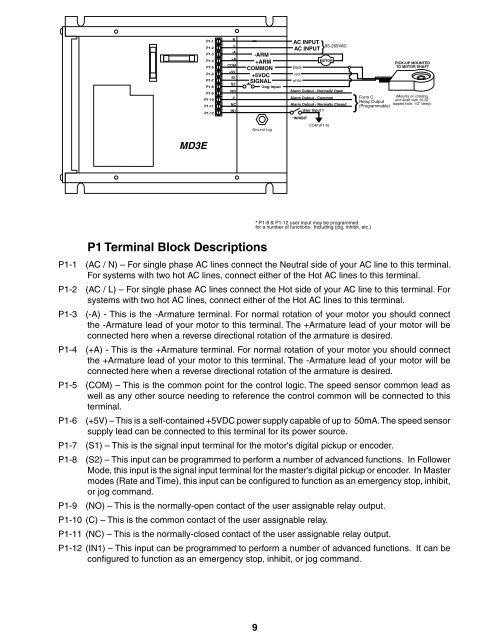
P1-1P1-2P1-3P1-4P1-5P1-6P1-7P1-8P1-9P1-10P1-11P1-12NL-A+ACOM+5VS1S2NOCNCIN1-ARM+ARMCOMMON+5VDCSIGNAL*Jog InputAC AC INPUT} 85-265VACblackredwhiteMOTORAlarm Output - Normally OpenAlarm Output - CommonAlarm Output - Normally ClosedUser Input 1*INHIBITPICK-UP MOUNTEDTO MOTOR SHAFTForm C(Mounts on rotatingRelay Outputend shaft with 10-32tapped hole, 1/2" deep)}(Programmable)Ground LugCOM (P1-5)MD3EP1 Terminal Block Descriptions* P1-8 & P1-12 user input may be programmedfor a number of functions. Including (jog, inhibit, etc.)P1-1 (AC / N) – For single phase AC lines connect the Neutral side of your AC line to this terminal.For systems with two hot AC lines, connect either of the Hot AC lines to this terminal.P1-2 (AC / L) – For single phase AC lines connect the Hot side of your AC line to this terminal. Forsystems with two hot AC lines, connect either of the Hot AC lines to this terminal.P1-3 (-A) - This is the -Armature terminal. For normal rotation of your motor you should connectthe -Armature lead of your motor to this terminal. The +Armature lead of your motor will beconnected here when a reverse directional rotation of the armature is desired.P1-4 (+A) - This is the +Armature terminal. For normal rotation of your motor you should connectthe +Armature lead of your motor to this terminal. The -Armature lead of your motor will beconnected here when a reverse directional rotation of the armature is desired.P1-5 (COM) – This is the common point for the control logic. The speed sensor common lead aswell as any other source needing to reference the control common will be connected to thisterminal.P1-6 (+5V) – This is a self-contained +5VDC power supply capable of up to 50mA. The speed sensorsupply lead can be connected to this terminal for its power source.P1-7 (S1) – This is the signal input terminal for the motor's digital pickup or encoder.P1-8 (S2) – This input can be programmed to perform a number of advanced functions. In FollowerMode, this input is the signal input terminal for the master's digital pickup or encoder. In Mastermodes (Rate and Time), this input can be configured to function as an emergency stop, inhibit,or jog command.P1-9 (NO) – This is the normally-open contact of the user assignable relay output.P1-10 (C) – This is the common contact of the user assignable relay.P1-11 (NC) – This is the normally-closed contact of the user assignable relay output.P1-12 (IN1) – This input can be programmed to perform a number of advanced functions. It can beconfigured to function as an emergency stop, inhibit, or jog command.9