TE525 Tipping Bucket Rain Gage - Campbell Scientific
TE525 Tipping Bucket Rain Gage - Campbell Scientific
TE525 Tipping Bucket Rain Gage - Campbell Scientific

You also want an ePaper? Increase the reach of your titles
YUMPU automatically turns print PDFs into web optimized ePapers that Google loves.
WarrantyThe <strong>TE525</strong>, <strong>TE525</strong>WS, and <strong>TE525</strong>MM are warranted for thirty-six (36)months subject to this limited warranty:“PRODUCTS MANUFACTURED BY CAMPBELL SCIENTIFIC, INC. arewarranted by <strong>Campbell</strong> <strong>Scientific</strong>, Inc. (“<strong>Campbell</strong>”) to be free from defects inmaterials and workmanship under normal use and service for twelve (12)months from date of shipment unless otherwise specified in the corresponding<strong>Campbell</strong> pricelist or product manual. Products not manufactured, but that arere-sold by <strong>Campbell</strong>, are warranted only to the limits extended by the originalmanufacturer. Batteries, fine-wire thermocouples, desiccant, and otherconsumables have no warranty. <strong>Campbell</strong>’s obligation under this warranty islimited to repairing or replacing (at <strong>Campbell</strong>’s option) defective products,which shall be the sole and exclusive remedy under this warranty. Thecustomer shall assume all costs of removing, reinstalling, and shippingdefective products to <strong>Campbell</strong>. <strong>Campbell</strong> will return such products by surfacecarrier prepaid within the continental United States of America. To all otherlocations, <strong>Campbell</strong> will return such products best way CIP (Port of Entry)INCOTERM® 2010, prepaid. This warranty shall not apply to any productswhich have been subjected to modification, misuse, neglect, improper service,accidents of nature, or shipping damage. This warranty is in lieu of all otherwarranties, expressed or implied. The warranty for installation servicesperformed by <strong>Campbell</strong> such as programming to customer specifications,electrical connections to products manufactured by <strong>Campbell</strong>, and productspecific training, is part of <strong>Campbell</strong>’s product warranty. CAMPBELLEXPRESSLY DISCLAIMS AND EXCLUDES ANY IMPLIEDWARRANTIES OF MERCHANTABILITY OR FITNESS FOR APARTICULAR PURPOSE. <strong>Campbell</strong> is not liable for any special, indirect,incidental, and/or consequential damages.”
AssistanceProducts may not be returned without prior authorization. The followingcontact information is for US and international customers residing in countriesserved by <strong>Campbell</strong> <strong>Scientific</strong>, Inc. directly. Affiliate companies handlerepairs for customers within their territories. Please visitwww.campbellsci.com to determine which <strong>Campbell</strong> <strong>Scientific</strong> company servesyour country.To obtain a Returned Materials Authorization (RMA), contact CAMPBELLSCIENTIFIC, INC., phone (435) 227-9000. After an application engineerdetermines the nature of the problem, an RMA number will be issued. Pleasewrite this number clearly on the outside of the shipping container. <strong>Campbell</strong><strong>Scientific</strong>’s shipping address is:CAMPBELL SCIENTIFIC, INC.RMA#_____815 West 1800 NorthLogan, Utah 84321-1784For all returns, the customer must fill out a “Statement of Product Cleanlinessand Decontamination” form and comply with the requirements specified in it.The form is available from our web site at www.campbellsci.com/repair. Acompleted form must be either emailed to repair@campbellsci.com or faxed to(435) 227-9106. <strong>Campbell</strong> <strong>Scientific</strong> is unable to process any returns until wereceive this form. If the form is not received within three days of productreceipt or is incomplete, the product will be returned to the customer at thecustomer’s expense. <strong>Campbell</strong> <strong>Scientific</strong> reserves the right to refuse service onproducts that were exposed to contaminants that may cause health or safetyconcerns for our employees.
Table of ContentsPDF viewers: These page numbers refer to the printed version of this document. Use thePDF reader bookmarks tab for links to specific sections.1. Introduction.................................................................12. Cautionary Statements...............................................13. Initial Inspection .........................................................13.1 Ships With............................................................................................24. Quickstart ....................................................................24.1 Siting ....................................................................................................24.2 Mounting..............................................................................................24.3 Use SCWin to Program Datalogger and Generate Wiring Diagram ....45. Overview......................................................................75.1 Wind Screen.........................................................................................75.2 Snowfall Adapter .................................................................................76. Specifications .............................................................87. Operation.....................................................................97.1 Wiring ..................................................................................................97.2 Datalogger Programming ...................................................................107.2.1 Pulse Count Example Programs..................................................117.2.1.1 CR1000 Example Program...............................................117.2.1.2 CR200(X) Series Example Program ................................117.2.2 Control Port Example..................................................................127.2.2.1 CR1000 Example Program...............................................128. Troubleshooting........................................................129. Maintenance ..............................................................12AppendixA. Edlog Program Examples ...................................... A-1A.1 CR10X Pulse Count Example Program .......................................... A-1A.2 CR10X Control Port Example......................................................... A-2i
Table of ContentsFiguresTables4-1. <strong>TE525</strong> <strong>Tipping</strong> <strong>Bucket</strong> <strong>Rain</strong> <strong>Gage</strong> ...................................................... 34-2. Pedestal base options........................................................................... 37-1. <strong>Rain</strong> <strong>Gage</strong> Schematic ........................................................................ 107-1. Wiring for Pulse Channel Input........................................................... 97-2. Wiring for Control Port Input.............................................................. 97-3. Multipliers for <strong>Rain</strong> Measurement .................................................... 10ii
<strong>TE525</strong> <strong>Tipping</strong> <strong>Bucket</strong> <strong>Rain</strong> <strong>Gage</strong>1. IntroductionThe <strong>TE525</strong> is an adaptation of the standard National Weather Service tippingbucket rain gage. Output is a switch closure for each bucket tip. Three modelsare available:• <strong>TE525</strong> 6 in. orifice 0.01 in. tip• <strong>TE525</strong>WS 8 in. orifice 0.01 in. tip• <strong>TE525</strong>MM 24.5 cm orifice 0.1 mm tipBefore installing the <strong>TE525</strong>, please study:2. Cautionary Statements3. Initial Inspection• Section 2, Cautionary Statements• Section 3, Initial Inspection• Section 4, Quickstart• The <strong>TE525</strong>-series tipping bucket rain gages are precision instruments.Please handle them with care.• Care should be taken when opening the package not to damage or cut thecable jacket.• Sensor is factory calibrated and should not require field calibration. Referto Section 9, Maintenance, for field calibration check and factorycalibration.• Debris filters, funnel, and bucket reservoirs should be kept clean.• The black outer jacket of the cable is Santoprene ® rubber. This compoundwas chosen for its resistance to temperature extremes, moisture, and UVdegradation. However, this jacket will support combustion in air. It israted as slow burning when tested according to U.L. 94 H.B. and will passFMVSS302. Local fire codes may preclude its use inside buildings.• Upon receipt of the tipping bucket, inspect the packaging and contents fordamage. File damage claims with the shipping company.• Immediately check package contents against the shipping documentation(see Section 3.1, Ships With). Contact <strong>Campbell</strong> <strong>Scientific</strong> about anydiscrepancies.• The model number and cable length are printed on a label at theconnection end of the cable. Check this information against the shippingdocuments to ensure the expected product and cable length are received.1
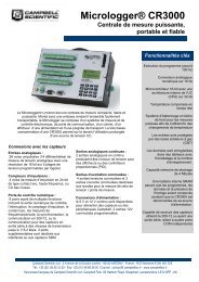
<strong>TE525</strong> <strong>Tipping</strong> <strong>Bucket</strong> <strong>Rain</strong> <strong>Gage</strong>3.1 Ships WithThe <strong>TE525</strong> ships with:(1) Calibration sheet(2) Hose clamps from original manufacturer(1) ResourceDVD(3) Screws from original manufacturer4. Quickstart4.1 SitingPlease review Section 7, Operation, for wiring, CRBasic programming, andEdlog programming.The rain gage should be mounted in a relatively level spot which isrepresentative of the surrounding area. The lip of the funnel should behorizontal and at least 30 cm above the ground. It should be high enough to beabove the average snow depth. The ground surface around the rain gageshould be natural vegetation or gravel. It should not be paved.The rain gage should be placed away from objects that obstruct the wind. Thedistance should be 2 to 4 times the height of the obstruction.• The pipe used to mount the bucket must be vertical. Use a torpedo level orsomething similar to get it as vertical as possible.• Take the funnel off of the top of the bucket and look inside towards thebottom of the bucket — notice the bubble level. Center the bubble levelwhile mounting the bucket to the pipe. Replace the funnel and seat itcompletely when the installation is complete.4.2 MountingThe CM300-series mounting poles provide a stainless steel 1.5 IPS verticalpole for mounting the <strong>TE525</strong> rain gage. Pole length is 58 cm (23 in), 119 cm(47 in), and 142 cm (53 in) for the CM300, CM305, and CM310 modelsrespectively. The CM300-series offers pedestal base options as well, as shownin FIGURE 4-2.Use the enclosed hose clamps to mount the gage as shown in FIGURE 4-1.The lip of the gage should be at least 5 cm (2 in) above the post or pole. Levelthe rain gage after mounting it.NOTEBefore final leveling, press either end of the bucket down againstits stop to make sure the bucket is NOT hung up in the center.2
<strong>TE525</strong> <strong>Tipping</strong> <strong>Bucket</strong> <strong>Rain</strong> <strong>Gage</strong>24”8”FIGURE 4-1. <strong>TE525</strong> <strong>Tipping</strong> <strong>Bucket</strong> <strong>Rain</strong> <strong>Gage</strong>FIGURE 4-2. Pedestal base options3
<strong>TE525</strong> <strong>Tipping</strong> <strong>Bucket</strong> <strong>Rain</strong> <strong>Gage</strong>4.3 Use SCWin to Program Datalogger and Generate WiringDiagramThe simplest method for programming the datalogger to measure the tippingbucket rain gages is to use <strong>Campbell</strong> <strong>Scientific</strong>’s SCWin Program Generator(Short Cut).NOTEThis section shows Short Cut’s programming for the<strong>TE525</strong>/<strong>TE525</strong>WS. The TE52MM is done similarly.1. Open Short Cut and click on New Program.2. Select the Datalogger and enter the Scan Interval.4
<strong>TE525</strong> <strong>Tipping</strong> <strong>Bucket</strong> <strong>Rain</strong> <strong>Gage</strong>3. Select <strong>TE525</strong>/<strong>TE525</strong>WS <strong>Rain</strong> Gauge, and select the right arrow (incenter of screen) to add it to the list of sensors to be measured, and thenselect Next.4. Define the name of the public variable and the measurement units.After entering the information, click on OK, and then select Next.5
<strong>TE525</strong> <strong>Tipping</strong> <strong>Bucket</strong> <strong>Rain</strong> <strong>Gage</strong>5. Choose the Output and then select Finish.6. In the Save As window, enter an appropriate file name and select Save.7. In the Confirm window, click Yes to download the program to thedatalogger.8. Click on Wiring Diagram and wire according to the wiring diagramgenerated by Short Cut.6
<strong>TE525</strong> <strong>Tipping</strong> <strong>Bucket</strong> <strong>Rain</strong> <strong>Gage</strong>5. OverviewThe <strong>TE525</strong>-series tipping bucket rain gages funnel precipitation into a bucketmechanism that tips when filled to a calibrated level. A magnet attached to thetipping mechanism actuates a switch as the bucket tips. The momentary switchclosure is counted by the pulse-counting circuitry of <strong>Campbell</strong> <strong>Scientific</strong>dataloggers.The <strong>TE525</strong>-series tipping bucket rain gages are manufactured by TexasElectronics and then cabled by <strong>Campbell</strong> <strong>Scientific</strong>. The –L after the modelnumber indicates the cable length is specified when ordered. The cable canterminate in:• Pigtails that connect directly to a <strong>Campbell</strong> <strong>Scientific</strong> datalogger(option –PT).• Connector that attaches to a prewired enclosure (option –PW). Referto www.campbellsci.com/prewired-enclosures for more information.• Connector that attaches to a CWS900 Wireless Sensor Interface(option –CWS). The CWS900 allows the probe to be used in awireless sensor network. Refer to www.campbellsci.com/cws900 formore information.• Connector that attaches to a CS110 Electric Field Meter or ET-seriesweather station (cable termination option –C).• Military-style connector that attaches to a RAWS-P PermanentRemote Automated Weather Station (cable termination option –RQ).This option is not available for the <strong>TE525</strong>MM.5.1 Wind Screen5.2 Snowfall Adapter<strong>Campbell</strong> <strong>Scientific</strong> offers the 260-953 Wind Screen to help minimize theeffect of wind on the rain measurements. This wind screen consists of 32leaves that hang freely and swing as wind moves past them. Refer to the 260-953 manual for siting information and the installation procedure.<strong>Campbell</strong> <strong>Scientific</strong>’s CS705 Snowfall Conversion Adapter uses antifreeze tomelt snow, allowing the <strong>TE525</strong>WS to measure the water content of snow. TheCS705 cannot be directly used with either the <strong>TE525</strong> or <strong>TE525</strong>MM. However,both the <strong>TE525</strong> and <strong>TE525</strong>MM can be converted to a <strong>TE525</strong>WS by returningthem to <strong>Campbell</strong> <strong>Scientific</strong> (see Assistance page at the beginning of thisdocument). Refer to the CS705 manual for siting information and theinstallation procedure.7
<strong>TE525</strong> <strong>Tipping</strong> <strong>Bucket</strong> <strong>Rain</strong> <strong>Gage</strong>6. SpecificationsFeatures:• High precision• Compatible with all <strong>Campbell</strong> <strong>Scientific</strong> dataloggers (including theCR200(X) series)• <strong>TE525</strong>WS conforms to the National Weather Servicerecommendation for an 8-inch funnel orifice.• <strong>TE525</strong>WS is directly compatible with the CS705 Snowfall Adapterallowing it to measure the measure the water content of snow.• <strong>Campbell</strong> <strong>Scientific</strong> can modify a <strong>TE525</strong> or <strong>TE525</strong>MM to it to beused with the CS705 Snowfall Adapter. Refer to Assistance page atthe beginning of this document for the procedure for sending thetipping bucket to <strong>Campbell</strong> <strong>Scientific</strong>.Compatible Dataloggers:CR200(X)-seriesCR800 seriesCR1000CR3000CR5000CR9000XCR510CR500CR10(X)CR23XCR721XSensor Type<strong>TE525</strong> <strong>TE525</strong>WS <strong>TE525</strong>MMtipping bucket/potted magnetic momentary contact reed switchSwitch Ratings 30 Vdc at 2 A; 115 Vac at 1 A;closure time: 135 ms; bounce settling time: 0.75 ms<strong>Bucket</strong> MaterialFunnel Collector MaterialScreen MaterialLocking Snap Ring MaterialOperating TemperatureResolutionVolume per Tip4.73 ml/tip(0.16 fl. oz/tip)white powder coated spun aluminumgold anodized spun aluminumgold anodized spun aluminumstainless steel0° to +50°C (32° to 125°F)1 tip8.24 ml/tip(0.28 fl. oz/tip)4.73 ml/tip(0.16 fl. oz/tip)<strong>Rain</strong>fall per Tip 0.01 in (0.254 mm) 0.1 mm (0.004 in)Accuracy1.0% up to 2 in/hour (50 mm/hr)Knife Edge Funnel Collector Diameter 15.4 cm (6.1 in) 20.3 cm (8 in) 24.5 cm (9.7 in)8
<strong>TE525</strong> <strong>Tipping</strong> <strong>Bucket</strong> <strong>Rain</strong> <strong>Gage</strong><strong>TE525</strong> <strong>TE525</strong>WS <strong>TE525</strong>MMHeight 24.1 cm (9.5 in) 26.7 cm (10.5 in) 29.2 cm (11.5 in)<strong>Tipping</strong> <strong>Bucket</strong> Weight 0.9 kg (2 lb) 1 kg (2.2 lb) 1.1 kg (2.4 lb)Cable2-conductor shielded cableCable Weight0.1 kg (0.2 lb) per 10 ft length7. Operation7.1 WiringWhen Short Cut is used to generate the datalogger program, the sensor shouldbe wired to the channels shown on the wiring diagram created by Short Cut.The rain gage is typically wired to a datalogger’s pulse channel (see TABLE7-1).TABLE 7-1. Wiring for Pulse Channel InputColor|DescriptionCR800CR850CR1000CR3000CR5000CR9000(X)Black Signal PulseChannelWhiteSignalReturnClear Shield GCR510CR500CR10(X)PulseChannelG21XCR7CR23XPulseChannelCR200(X)SeriesP_SWDataloggers listed in TABLE 7-2 have the capability of counting switchclosures on some of their control ports. When a control port is used, the returnfrom the rain gage switch must be connected to +5 V on the datalogger.ColorDescriptionTABLE 7-2. Wiring for Control Port InputCR800CR850CR1000CR3000CR500CR510 CR10X CR23XBlack Signal Control Port C2/P3 Control Port Control PortWhite Signal Return 5 V 5 V 5 V 5 VClear Shield G9
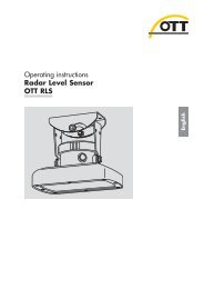
<strong>TE525</strong> <strong>Tipping</strong> <strong>Bucket</strong> <strong>Rain</strong> <strong>Gage</strong>The CR10 does not support the use of control port inputs with the Pulse Countinstruction.BlackWhiteClear100 ΩFIGURE 7-1. <strong>Rain</strong> <strong>Gage</strong> SchematicIn a long cable, there is appreciable capacitance between the lines. A built upcharge could cause arcing when the switch closes, shortening switch life. A100 Ω resistor is connected in series at the switch to prevent arcing by limitingthe current (FIGURE 7-1). This resistor is installed on all rain gages currentlysold by <strong>Campbell</strong> <strong>Scientific</strong>.7.2 Datalogger ProgrammingThis section is for users who write their own programs. A datalogger programto measure this sensor can be generated using Short Cut. You do not need toread this section to use Short Cut.In CRBasic, the rain gage is measured using the PulseCount() instruction.Choose switch closure (code 2) for the PConfig parameter. Dataloggers thatuse CRBasic are the CR200(X), CR800, CR850, CR1000, CR3000, CR5000,and CR9000(X).In Edlog, the Pulse (P3) is used to measure the rain gage. Choose switchclosure (code 2) for parameter three. Dataloggers that use Edlog are theCR500, CR510, CR10(X), CR23X, CR7, and 21X.The multiplier used in the PulseCount() or Pulse (P3) instruction determinesthe units in which rainfall is reported (see TABLE 7-3).TABLE 7-3. Multipliers for <strong>Rain</strong> Measurement<strong>Rain</strong> <strong>Gage</strong> inches millimeters<strong>TE525</strong> 0.01 0.254<strong>TE525</strong>WS 0.01 0.254<strong>TE525</strong>MM 0.00394 0.1<strong>TE525</strong> or <strong>TE525</strong>MM w/8 in funnel 0.0057 0.1459The volume of water required to cause a tip in the <strong>TE525</strong> and the <strong>TE525</strong>MM isthe same. The difference in calibration is strictly due to funnel size. If theCS705 Snowfall Adapter or other eight inch funnel is installed on these gages,use a multiplier from the last row in TABLE 7-3. (The CS705 will not installdirectly on the <strong>TE525</strong>MM; the MM funnel must first be replaced with an eightinch funnel.)10
<strong>TE525</strong> <strong>Tipping</strong> <strong>Bucket</strong> <strong>Rain</strong> <strong>Gage</strong>7.2.1 Pulse Count Example ProgramsThe following example programs use a pulse channel to read the output fromthe rain gage. The CR1000 example will also work with the CR800, CR850,CR3000, and CR5000. CR9000(X) programming is similar to the CR1000except it has an additional parameter in the PulseCount() instruction to specifythe pulse module’s slot.7.2.1.1 CR1000 Example Program'CR1000'<strong>TE525</strong>/<strong>TE525</strong>WS & <strong>TE525</strong>MM sample programPublic <strong>Rain</strong>_mmUnits <strong>Rain</strong>_mm=mmDataTable(<strong>Rain</strong>,True,-1)DataInterval(0,60,Min,0)Totalize(1,<strong>Rain</strong>_mm,FP2,0)EndTableBeginProgScan(1,Sec,1,0)'For <strong>TE525</strong>MM <strong>Rain</strong> <strong>Gage</strong>, use multiplier of 0.1 in PulseCount instructionPulseCount(<strong>Rain</strong>_mm,1,1,2,0,0.254,0)CallTable(<strong>Rain</strong>)NextScanEndProg7.2.1.2 CR200(X) Series Example Program'CR200(X) Series'Declare Variables and UnitsPublic <strong>Rain</strong>_mmUnits <strong>Rain</strong>_mm=mm'Define Data TablesDataTable(<strong>Rain</strong>,True,-1)DataInterval(0,60,Min)Totalize(1,<strong>Rain</strong>_mm,0)EndTable'Main ProgramBeginProgScan(1,Sec)'<strong>TE525</strong>/<strong>TE525</strong>WS <strong>Rain</strong> <strong>Gage</strong> measurement <strong>Rain</strong>_mm:PulseCount(<strong>Rain</strong>_mm,P_SW,2,0,0.254,0)'Call Data Tables and Store DataCallTable(<strong>Rain</strong>)NextScanEndProg'For <strong>TE525</strong>MM <strong>Rain</strong> <strong>Gage</strong>, use multiplier of 0.1 in PulseCount instruction11
<strong>TE525</strong> <strong>Tipping</strong> <strong>Bucket</strong> <strong>Rain</strong> <strong>Gage</strong>7.2.2 Control Port ExampleThis example measures a <strong>TE525</strong> rain gage in millimeters. A differentmultiplier would be entered (TABLE 7-3) for other units.7.2.2.1 CR1000 Example Program'CR1000'Declare Public Variables and UnitsPublic <strong>Rain</strong>_mmUnits <strong>Rain</strong>_mm=mmDataTable (<strong>Rain</strong>,True,-1)DataInterval (0,60,Min,0)Totalize (1,<strong>Rain</strong>_mm,FP2,0)EndTable'Main ProgramBeginProgScan (1,Sec,1,0)'For <strong>TE525</strong>MM <strong>Rain</strong> <strong>Gage</strong> use multiplier of 0.1 in PulseCount Instruction.PulseCount (<strong>Rain</strong>_mm,1,18,2,0,.254,0)CallTable (<strong>Rain</strong>)NextScanEndProg8. Troubleshooting9. MaintenanceSymptom: No Precipitation1. Check that the sensor is wired to the Pulse Channel specified by the pulsecount instruction.2. Verify that the Configuration Code (Switch Closure), and Multiplier andOffset parameters for the Pulse Count instruction are correct for thedatalogger type.3. Disconnect the sensor from the datalogger and use an ohm meter to do acontinuity check of the switch. The resistance measured at the terminalblock on the inside of the bucket between the black and white leadsshould vary from infinite (switch open) when the bucket is tipped, to lessthan an ohm when the bucket is balanced.The funnel and bucket mechanism must be kept clean. Routinely check for andremove any foreign material, dust, insects, etc. The following calibrationcheck is advised every 12 months.Field Calibration Check:(1) Secure a metal can that will hold at least one quart of water.(2) Punch a very small hole in the bottom of the can.12
<strong>TE525</strong> <strong>Tipping</strong> <strong>Bucket</strong> <strong>Rain</strong> <strong>Gage</strong>(3) Place the can in the top funnel of the rain gage and pour 16 fluid ounces (1pint) of water into the can. (A 16 oz. soft drink bottle filled to within 2.5inches of the top may be used for a rough field calibration. An exactvolume will allow for a more precise calibration).(4) If it takes less than 45 minutes for this water to run out, the hole in the canis too large.(5) The following number of tips should occur:<strong>TE525</strong>, <strong>TE525</strong>MM 100 ± 3<strong>TE525</strong>WS 57 ± 2(6) Adjusting screws are located on the bottom adjacent to the large centerdrain hole. Adjust both screws the same number of turns. Rotationclockwise increases the number of tips per 16 oz. of water; counterclockwise rotation decreases the number of tips per 16 oz. of water. Onehalf turn of both screws causes a 2% to 3% change.(7) Check and re-level the rain gage lid.Factory Calibration:If factory calibration is required, contact <strong>Campbell</strong> <strong>Scientific</strong> to obtain an RMA(see Warranty and Assistance at front of manual).13
<strong>TE525</strong> <strong>Tipping</strong> <strong>Bucket</strong> <strong>Rain</strong> <strong>Gage</strong>14
Appendix A. Edlog Program ExamplesA.1 CR10X Pulse Count Example ProgramThe CR10X program will also work with the CR500, CR510, CR10, 21X orCR23X. CR7 programming is similar to the CR10X but has an additionalparameter in the Pulse (P3) instruction to specify the slot that the pulse card isin.;{CR10X}*Table 1 Program01: 1.0000 Execution Interval (seconds)1: Pulse (P3)1: 1 Reps2: 1 Pulse Channel 13: 2 Switch Closure, All Counts4: 3 Loc [ <strong>Rain</strong>_mm ]5: 0.254 Multiplier6: 0 Offset2: If time is (P92)1: 0 Minutes (Seconds --) into a2: 60 Interval (same units as above)3: 10 Set Output Flag High (Flag 0)3: Set Active Storage Area (P80)1: 1 Final Storage Area 12: 101 Array ID4: Real Time (P77)1: 1220 Year,Day,Hour/Minute (midnight = 2400)5: Totalize (P72)1: 1 Reps2: 3 Loc [ <strong>Rain</strong>_mm ]*Table 2 Program01: 0 Execution Interval (seconds)*Table 3 SubroutinesEnd ProgramA-1
Appendix A. Edlog Program ExamplesA.2 CR10X Control Port ExampleThis example measures a <strong>TE525</strong> rain gage in millimeters. A differentmultiplier would be entered (TABLE 7-3) for other units.;{CR10X};*Table 1 Program01: 1 Execution Interval (seconds)1: Pulse (P3)1: 1 Reps2: 8 Control Port 8 (switch closure only) ;Black wire connect to C83: 2 Switch Closure, All Counts4: 1 Loc [ <strong>Rain</strong>_mm ]5: .254 Multiplier6: 0 Offset2: If time is (P92)1: 0 Minutes (Seconds --) into a2: 60 Interval (same units as above)3: 10 Set Output Flag High (Flag 0)3: Set Active Storage Area (P80)1: 1 Final Storage Area 12: 101 Array ID4: Real Time (P77)1: 1220 Year,Day,Hour/Minute (midnight = 2400)5: Totalize (P72)1: 1 Reps2: 1 Loc [ <strong>Rain</strong>_mm ]*Table 2 Program02: 0.0000 Execution Interval (seconds)*Table 3 SubroutinesEnd ProgramOutput Instruction 72, Totalize, is used in the output section of the program tooutput the total rainfall over the output interval. This section should beexecuted every scan and not placed in a subroutine or conditional statement.A-2
<strong>Campbell</strong> <strong>Scientific</strong> Companies<strong>Campbell</strong> <strong>Scientific</strong>, Inc. (CSI)815 West 1800 NorthLogan, Utah 84321UNITED STATESwww.campbellsci.com • info@campbellsci.com<strong>Campbell</strong> <strong>Scientific</strong> Africa Pty. Ltd. (CSAf)PO Box 2450Somerset West 7129SOUTH AFRICAwww.csafrica.co.za • cleroux@csafrica.co.za<strong>Campbell</strong> <strong>Scientific</strong> Australia Pty. Ltd. (CSA)PO Box 8108Garbutt Post Shop QLD 4814AUSTRALIAwww.campbellsci.com.au • info@campbellsci.com.au<strong>Campbell</strong> <strong>Scientific</strong> do Brasil Ltda. (CSB)Rua Apinagés, nbr. 2018 ─ PerdizesCEP: 01258-00 ─ São Paulo ─ SPBRASILwww.campbellsci.com.br • vendas@campbellsci.com.br<strong>Campbell</strong> <strong>Scientific</strong> Canada Corp. (CSC)11564 - 149th Street NWEdmonton, Alberta T5M 1W7CANADAwww.campbellsci.ca • dataloggers@campbellsci.ca<strong>Campbell</strong> <strong>Scientific</strong> Centro Caribe S.A. (CSCC)300 N Cementerio, Edificio BrellerSanto Domingo, Heredia 40305COSTA RICAwww.campbellsci.cc • info@campbellsci.cc<strong>Campbell</strong> <strong>Scientific</strong> Ltd. (CSL)<strong>Campbell</strong> Park80 Hathern RoadShepshed, Loughborough LE12 9GXUNITED KINGDOMwww.campbellsci.co.uk • sales@campbellsci.co.uk<strong>Campbell</strong> <strong>Scientific</strong> Ltd. (CSL France)3 Avenue de la Division Leclerc92160 ANTONYFRANCEwww.campbellsci.fr • info@campbellsci.fr<strong>Campbell</strong> <strong>Scientific</strong> Ltd. (CSL Germany)Fahrenheitstraße 1328359 BremenGERMANYwww.campbellsci.de • info@campbellsci.de<strong>Campbell</strong> <strong>Scientific</strong> Spain, S. L. (CSL Spain)Avda. Pompeu Fabra 7-9, local 108024 BarcelonaSPAINwww.campbellsci.es • info@campbellsci.esPlease visit www.campbellsci.com to obtain contact information for your local US or international representative.