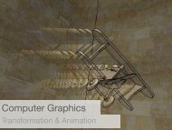
Virtual Reality as a Human Computer Interface to Mechanical Design
Virtual Reality as a Human Computer Interface to Mechanical Design
Virtual Reality as a Human Computer Interface to Mechanical Design
- No tags were found...

You also want an ePaper? Increase the reach of your titles
YUMPU automatically turns print PDFs into web optimized ePapers that Google loves.
<strong>Virtual</strong> <strong>Reality</strong><strong>as</strong> a <strong>Human</strong> <strong>Computer</strong> <strong>Interface</strong><strong>to</strong> <strong>Mechanical</strong> <strong>Design</strong>Judy M. Vance<strong>Mechanical</strong> Engineering Department<strong>Virtual</strong> <strong>Reality</strong> Applications CenterIowa State UniversityAmes, IA
Presentation Outline• <strong>Virtual</strong> <strong>Reality</strong> Applications Center• Implementing a Haptic <strong>Interface</strong> in aProjection System Environment• <strong>Virtual</strong> Hydraulic Hose Routing• Ergonomic <strong>Design</strong> using 3D <strong>Human</strong>Anthropometric Data
<strong>Virtual</strong> <strong>Reality</strong> Applications CenterTo be a national leader in theMissionapplication of virtual reality <strong>to</strong> thechallenges of science andengineering34 Facultyfrom 16 Departments and 4 Colleges76 Graduate Students59 Undergraduate Students
Facilities20,000 sg. ft. labora<strong>to</strong>ry/office complex inHowe Hall
Facilities
Immersive Projection FacilitiesBlack Engineering BuildingC4MD FlexHowe HallC66 wallLee LiuAudi<strong>to</strong>riumHowe Hall
C4: MD Flex• 12' x 12' x 9' facility• 3 walls and floor stereo projection• Outer walls can fold out <strong>to</strong> provide a 36' x9' viewing surface• SGI ONYX with 3 - Infinite <strong>Reality</strong>graphics pipes and 16 - R10000 processors• Nuvision andStereoGraphics activestereo gl<strong>as</strong>ses• Ascension TechnologyWireless MotionStartracking system• Barco projec<strong>to</strong>rs
The C6Entire facility is 3 s<strong>to</strong>rieshighOccupies the atrium ofHowe Hall
C6: 6 walls, wireless tracking• 10' x 10' x 10' facility• 4 walls, floor, and ceiling stereo projection• Surround sound audio system• SGI ONYX2 <strong>Reality</strong> Monster• 6 - Infinite <strong>Reality</strong>2 graphic pipes• 24 - R12000 processors @ 400 MHz• 256MB texture memory, 12Gb RAM• Nuvision and StereoGraphicsactive stereo gl<strong>as</strong>ses• Ascension Technology WirelessMotionStar tracking system• Barco Projec<strong>to</strong>rs
MoviesSpatial Mechanism <strong>Design</strong>
MoviesCFD Particle Tracing During Mixing
Implementing a Haptic <strong>Interface</strong> ina Projection System EnvironmentGOAL: To combine the PHANToM haptic devicewith a projection screen virtual environment andexplore the benefits haptic devices bring <strong>to</strong> this typeof immersive environment.
Motivation<strong>Virtual</strong> AssemblyInteractive Shape <strong>Design</strong>
Haptic DevicePhan<strong>to</strong>m 1.5• Most common haptic device• Generally used on thedesk<strong>to</strong>pChallenges• Mobility• Scaling• Occlusion• Tracker interference
Implementation• PHANToM Stand• PHANToM Volume• PHANToM Driver
PHANToM Stand• Movable• Height adjustable• Non-magnetic
Phan<strong>to</strong>m VolumeCreate a 3D volume in the virtual environmentthat encomp<strong>as</strong>ses the part of the geometry thatwill be haptically enabled.Map the workspace extents of the haptic device<strong>to</strong> be constrained <strong>to</strong> this defined volume.
Phan<strong>to</strong>m VolumeDevice Workspace<strong>Virtual</strong> WorkspacePhan<strong>to</strong>m Volume
Workspace Scaling• Maintain <strong>as</strong>pect ratio• Use a single scale value• Constrain the physical workspace of the PHANToMaworld_haptic_scalemax_device _ workspace_dimensionmax_virtual _ volume_dimensionDevice workspace<strong>Virtual</strong> volume
PHANToM Driver• Controls PHANToMthrough GHOST• Haptic scene graph• Positions PHANToMin virtual space• Interacts with VrJuggler
PHANToM DriverHandles haptic process
Two Example ProgramsNURBS Surface• Feel a surface• Use GHOST defined haptic geometryRudder Pedal Installation• Part manipulation with haptics• Use VPS <strong>to</strong> determine collision forces
NURBS Surface Example• NURBS surface created• Polygonal Approximation• GHOST TriPolyMesh Object• Phan<strong>to</strong>m Volume
<strong>Virtual</strong> Assembly Example• Rudder Pedal Installation• Complex Geometry
VPS (Voxmap PointShell)• Rapid collision detection• Trade accuracy for speed• Voxel representation• Dynamic object + staticenvironment• Physically b<strong>as</strong>ed modeling
Modified Haptic Process• Dynamic Object Updated• VPS Detects Collisions• VPS Physically B<strong>as</strong>ed Modeling Determines Forces• GHOST queries VPS for position of endpoint andforces
Benefits• Intuitive partmanipulation with hapticfeedback• E<strong>as</strong>y <strong>to</strong> investigateinterference issuesbecause of immersion• E<strong>as</strong>y <strong>to</strong> collaborate
Future Work• Separate Haptic <strong>Computer</strong>• Other Haptic Devices• 6 Degree of Freedom PHANToM• CyberForce• Phan<strong>to</strong>m Stand Position/Mobility• Phan<strong>to</strong>m Volume Geometry
Hydraulic Hose Routingin <strong>Virtual</strong> <strong>Reality</strong>GOAL: To develop a virtual reality design<strong>to</strong>ol that allows designers <strong>to</strong> accuratelyroute hydraulic hoses early in the productdesign process.
The Hose Routing Problem• Difficult <strong>to</strong> predict installedhose shape• Hoses vary in flexibility• Installation affects hoseshape• Operation affects hoseshape• Multiple hoses are needed formany products• Hose wear occurs when hoses rubagainst other objects or other hoses
Current State of the Art• Hoses added <strong>to</strong> CAD model• ProPiping• Adams Hose Routing Module• “Enough room” for hoses is left in product design• Expert hose designers take their “best guess” onhose shape for the stiffest or most critical hosesoror
Why <strong>Virtual</strong> <strong>Reality</strong>?• VR provides a three-dimensional interface <strong>to</strong>computer models• Three-dimensional representation of the productdesign exists early in the design process• VR allows for natural interaction andexamination of spatial relationships
JACK TM<strong>Human</strong> figure modeling softwareAdvantages• Loads CAD geometry• View geometry in the HMDthrough JACK’s eyes• Position tracking• JackScript (Python + JACK)
VRHose Hardware• <strong>Virtual</strong> Research HMD• Ascension Flock of Birds Trackers• Fakespace Pinch Gloves• Switch Box for menus• SGI ONYX2 or Octane
VRHose Program• Series of JackScript code cl<strong>as</strong>ses• Geometry loaded from existing CAD models• Cus<strong>to</strong>m menu system• Analyzes hose shape with ADAMS• Load and Save hose routes
Hose TestingAxialTorsionBending
Hose Modeling• Hose points• Clamping constraints• Physical hose properties• Weight per unit length• Inside diameter• Outside diameter• Axial stiffness• Torsional stiffness• Bending stiffnessyxy(b)Calculated hose shapex(a)Initial hose points
Hose Modeling
Hose Routing Steps1. Load part geometry and hose port locations2. Select hose type and size from menu3. Choose and place connecting hardware4. Specify hose path with “hose points”
Hose Routing Steps5. Observe B-spline interpolation of hose path6. Modify “hose points” <strong>as</strong> needed7. Analyze hose path <strong>to</strong> obtain actual hose route8. Repeat 6 and 7 until satisfied9. Save final hose route
Conclusions• <strong>Virtual</strong> <strong>Reality</strong> provides e<strong>as</strong>y interaction and viewing• Placing and examining hose routes is f<strong>as</strong>t and intuitive• Hose analysis improved routing design
Future Work• Solve for the swept volume from a moving hose path• Incre<strong>as</strong>e the variety of available hose clamps
Ergonomic <strong>Design</strong> using 3D<strong>Human</strong> Anthropometry DataGOAL: To develop methods forergonomic design that take advantage ofthe availability of 3D humananthropometry data.
Traditional Methods ofErgonomic <strong>Design</strong>Traditional design usesone-dimensional data setsand the “percentile”approach95 th percentile male5 th percentile female
Traditional Methods ofErgonomic <strong>Design</strong>Problems with this approach include:• Dimensions are specific <strong>to</strong> thepopulation for which they werecalculated• Only one-dimensional data is used• Composite humans are used fordesign, rather than true humanrepresentations
Civilian American and EuropeanSurface AnthropometryResource (CAESAR)• Anthropometric data for ~4500civilians in the US and Europe• 3D (color) surface scans, ~70ana<strong>to</strong>mical landmark locations• Standing, seated working, andseated coverage postures
John Deere Survey• ~80 subjects seated in a JohnDeere seat• Dynamic motion path data forthe feet and hands• 12 John Deere subjectsparticipated in the CAESARproject
Application FeaturesUse of existing CAD geometry• Added <strong>to</strong> the scene graphand e<strong>as</strong>ily translated,rotated, scaled within theapplication
Application FeaturesElement selection withinthe scene graph• <strong>Design</strong>er may displaycomplete set of data forspecific population,one subject, or datarelevant <strong>to</strong> the design• Determinerepresentatives or“outliers”
Posture Data ExaminationPosturing information discernablethrough LineMen option• Connect maximal surfacelandmark locations• Connections specified by thedesignerAllows greater visibility of theindividual within the population
DiscussionImmersive application enables the use of current andfuture 3D anthropometric data sets
Discussion• No synthetic human representatives, not ahuman figure poser; designs b<strong>as</strong>ed onpopulation data and selected individuals• A population can be viewed in reference <strong>to</strong>a workstation layout allowing for rapidpro<strong>to</strong>typing and accommodation ofanthropometric differences
Future Work• Allow view <strong>to</strong> switch from third-person view <strong>to</strong><strong>as</strong>sume a particular subject’s view (first-personmode)• Allow for the ability <strong>to</strong> save selected sceneelements and workstation configurations• Provide filtering b<strong>as</strong>ed on demographic data• Add a joint-center model <strong>to</strong> facilitate posing of thelandmark and scan data
AcknowledgementsDeere & CompanyProcter and Gamble Company<strong>Virtual</strong> <strong>Reality</strong> Applications CenterNational Science FoundationMelinda CerneyKurt ChipperfieldDenis DorozhkineAndrew FischerChangEun KimScott Openshaw
More Informationwww.vrac.i<strong>as</strong>tate.eduwww.vrac.i<strong>as</strong>tate.edu/~jmvancewww.vrjuggler.org