Deflections of Thin-Walled Storage Tanks with Roof due to ...
Deflections of Thin-Walled Storage Tanks with Roof due to ...
Deflections of Thin-Walled Storage Tanks with Roof due to ...

You also want an ePaper? Increase the reach of your titles
YUMPU automatically turns print PDFs into web optimized ePapers that Google loves.
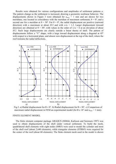
Results were obtained for various configurations and amplitudes <strong>of</strong> settlement patterns u.The pattern change as the settlement is increased, drawing a geometric nonlinear behavior. Thedisplacements shown in Figure 3 were obtained for u max = 1 mm and are shown for twomeridians, one located in coincidence <strong>with</strong> the meridian <strong>of</strong> maximum settlement, θ = 0º, and asecond one for a meridian at θ = 30º. For θ = 0º, the radial displacement are positive (outwarddirection) <strong>with</strong> a maximum at about H/3 and <strong>with</strong> w/u = 1.2. Larger displacement (inwarddirection) are obtained at θ = 30º, <strong>with</strong> values in the order <strong>of</strong> w/u = 6 at an elevation <strong>of</strong> aboutH/2. Such large displacements are clearly outside a linear theory <strong>of</strong> shell. The pattern <strong>of</strong>displacements follow a “V” shape, <strong>with</strong> a large inward displacement along a diagonal at 45º<strong>with</strong> respect <strong>to</strong> a horizontal plane, and almost zero displacement at the <strong>to</strong>p <strong>of</strong> the shell, where thero<strong>of</strong> restrains the radial deflections.98FEMEXPERIMENTAL98FEMEXPERIMENTAL98FEMEXPERIMENTAL7776665h /H45h /H45h /H433322211100.0 0.5 1.0 1.5RADIAL DISPLACEMENTa) b) c)Fig.3. a) Radial displacement for θ = 0°. b) Radial displacement for θ = 30°. c) Comparison <strong>of</strong>maximum radial displacement in FEM an experimental model (for θ ≅ 18° and u max = 1 mm).FINITE ELEMENT MODEL0-6 -5 -4 -3 -2 -1 0RADIAL DISPLACEMENTThe finite element computer package ABAQUS (Hibbitt, Karlsson and Sorensen 1997) wasused <strong>to</strong> obtain displacements <strong>of</strong> the shell under vertical settlement. To build the mesh,quadrilateral shell elements <strong>with</strong> eight nodes (S8R5) were used <strong>to</strong> model the cylinder and most<strong>of</strong> the shell ro<strong>of</strong> (about 2,640 elements), while triangular elements (STRI65) were required forthe center <strong>of</strong> the ro<strong>of</strong> (about 60 elements). The finite element mesh used in the model is shown0-6 -5 -4 -3 -2 -1 0RADIAL DISPLACEMENT