Deflections of Thin-Walled Storage Tanks with Roof due to ...
Deflections of Thin-Walled Storage Tanks with Roof due to ...
Deflections of Thin-Walled Storage Tanks with Roof due to ...

Create successful ePaper yourself
Turn your PDF publications into a flip-book with our unique Google optimized e-Paper software.
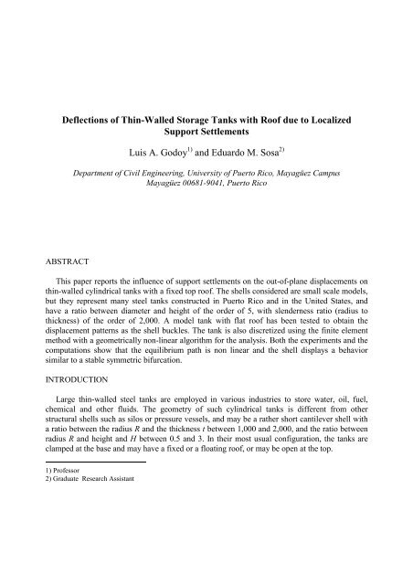
<strong>Deflections</strong> <strong>of</strong> <strong>Thin</strong>-<strong>Walled</strong> <strong>S<strong>to</strong>rage</strong> <strong>Tanks</strong> <strong>with</strong> Ro<strong>of</strong> <strong>due</strong> <strong>to</strong> LocalizedSupport SettlementsLuis A. Godoy 1) and Eduardo M. Sosa 2)Department <strong>of</strong> Civil Engineering, University <strong>of</strong> Puer<strong>to</strong> Rico, Mayagüez CampusMayagüez 00681-9041, Puer<strong>to</strong> RicoABSTRACTThis paper reports the influence <strong>of</strong> support settlements on the out-<strong>of</strong>-plane displacements onthin-walled cylindrical tanks <strong>with</strong> a fixed <strong>to</strong>p ro<strong>of</strong>. The shells considered are small scale models,but they represent many steel tanks constructed in Puer<strong>to</strong> Rico and in the United States, andhave a ratio between diameter and height <strong>of</strong> the order <strong>of</strong> 5, <strong>with</strong> slenderness ratio (radius <strong>to</strong>thickness) <strong>of</strong> the order <strong>of</strong> 2,000. A model tank <strong>with</strong> flat ro<strong>of</strong> has been tested <strong>to</strong> obtain thedisplacement patterns as the shell buckles. The tank is also discretized using the finite elementmethod <strong>with</strong> a geometrically non-linear algorithm for the analysis. Both the experiments and thecomputations show that the equilibrium path is non linear and the shell displays a behaviorsimilar <strong>to</strong> a stable symmetric bifurcation.INTRODUCTIONLarge thin-walled steel tanks are employed in various industries <strong>to</strong> s<strong>to</strong>re water, oil, fuel,chemical and other fluids. The geometry <strong>of</strong> such cylindrical tanks is different from otherstructural shells such as silos or pressure vessels, and may be a rather short cantilever shell <strong>with</strong>a ratio between the radius R and the thickness t between 1,000 and 2,000, and the ratio betweenradius R and height and H between 0.5 and 3. In their most usual configuration, the tanks areclamped at the base and may have a fixed or a floating ro<strong>of</strong>, or may be open at the <strong>to</strong>p.1) Pr<strong>of</strong>essor2) Graduate Research Assistant
<strong>Thin</strong>-walled metal tanks may be supported in various forms, including compact soilfoundation, ring walls, slabs or pile-supported foundations. The support may be lost in some part<strong>of</strong> the base circumference affecting the cylindrical shell and the tank bot<strong>to</strong>m (Myers 1997). Thecauses <strong>of</strong> differential settlements may include “non homogeneous geometry or compressibility<strong>of</strong> the soil deposit, non uniform distribution <strong>of</strong> the load applied <strong>to</strong> the foundation, and uniformstress acting over a limited area <strong>of</strong> the soil stratum” (Marr et al. 1982). But heavy rains, such asthose that happen during tropical s<strong>to</strong>rms and hurricanes, may aggravate such situations.The differential settlements may have several consequences:(a) Out-<strong>of</strong>-plane displacements are induced in the shell in the form <strong>of</strong> buckling under adisplacement-controlled mechanism;(b) High stresses develop at the base <strong>of</strong> the shell and in the region <strong>of</strong> the settlement;(c) High stresses develop in the tank bot<strong>to</strong>m.There are many reasons <strong>to</strong> be concerned about such stresses and dis<strong>to</strong>rtions: First, tanks arenot isolated from other parts in an industrial plant, but have pipes and connections <strong>to</strong> otherfacilities that may be damaged <strong>due</strong> <strong>to</strong> the vertical displacements. Second, excessivedisplacements in the cylindrical shell affect the normal operation <strong>of</strong> a floating ro<strong>of</strong>. Third, ageometric dis<strong>to</strong>rtion greatly affects the buckling resistance <strong>of</strong> the shell under wind. Fourth,plasticity may occur in parts <strong>of</strong> the shell wall.In this paper, the geometrical non-linear behavior <strong>of</strong> thin-walled tanks under localizedsettlements is considered, and it is assumed that the tank is empty when the settlement occurs.The main questions addressed are: What is the displacement pattern induced by verticalsettlements? For vertical displacements <strong>of</strong> the order <strong>of</strong> the thickness <strong>of</strong> the shell, are the radialdeflections <strong>with</strong>in the range <strong>of</strong> application <strong>of</strong> linear theory? Is it necessary <strong>to</strong> employ nonlinearkinematics relations for the shell?Part <strong>of</strong> this research is based on experiments on a small-scale model <strong>of</strong> a tank <strong>with</strong> a flat ro<strong>of</strong>,and on computer models <strong>of</strong> this tank carried out <strong>to</strong> validate the geometrical nonlinear behavior<strong>of</strong> this tank.LITERATURE REVIEWThe settlement <strong>of</strong> the foundation in large, thin walled shells has been <strong>of</strong> great concern in thepast. To evaluate the dis<strong>to</strong>rtions in the cylindrical part <strong>of</strong> the tank, various models have beenproposed, notably a harmonic shape <strong>to</strong> account for the vertical displacement at the base andwritten in the form:u = u n cos (n φ) (1)Where φ is the angle around the circumference and n is the wave number. Malik et al. (1977)used an inextensional theory <strong>of</strong> shells and derived the relation:w n = (H/R) n 2 u n (2)w n correspond <strong>to</strong> the maximum amplitude <strong>of</strong> the out-<strong>of</strong>-plane induced by the settlement.Kamyab and Palmer (1989) derived another expression <strong>to</strong> account the maximum amplitude <strong>of</strong>the out-<strong>of</strong>-plane displacement based on linear membrane shell theory given by:
w n = (H/R) n 2 u n [1/(1+α I ratio )] (3)Where α is function <strong>of</strong> the wave number n, the thickness t and <strong>of</strong> the Poisson’s relationν, andI ratio is the ratio between the circumferential bending stiffness <strong>of</strong> a ring stiffener on the <strong>to</strong>p andthe bending stiffness <strong>of</strong> the cylindrical shell. Jonaidi and Ansourian (1998) argued that errors inthe range <strong>of</strong> 10-18% are obtained from the use <strong>of</strong> this membrane model.More refined analysis have used finite element models for the shell and assumed harmonicsettlement (Jonaidi and Ansourian 1998) including more realistic features such as tapering wallthickness and the influence <strong>of</strong> the <strong>to</strong>p ring stiffener (wind girder). These authors used ABAQUS(Hibbitt, Karlsson and Sorensen 1997) <strong>to</strong> evaluate out-<strong>of</strong>-plane displacements, bending andmembrane stress resultants as a function <strong>of</strong> the wave number n. Their numerical results showedthat there is a critical value <strong>of</strong> n (close <strong>to</strong> 8) for which the displacements w n reach a maximumvalue.Experiments on small scale models have been done by D’Orazio et al. (1989) for an opencylinder supported on eight points around the perimeter, and the settlement in the labora<strong>to</strong>rymodel are related <strong>to</strong> wall movements in real tanks by:w real = (H/R) real K s (w R/H) model (4)In this equation w is the change in radius and K s is a fac<strong>to</strong>r <strong>of</strong> scale. Note that these expressionsare independent <strong>of</strong> the slenderness <strong>of</strong> the shell and represent a linear relation.Jonaidi and Ansourian (1998) reported tests on steel open cylinders <strong>with</strong> variable thicknessand a simulation <strong>of</strong> the <strong>to</strong>p ring. The mean wall-slenderness is R/t = 375 and R/H = 1.88. Thetests were performed at low amplitude settlements, consistent <strong>with</strong> the linear shell theory, andalso for large deflection, the main purpose being the evaluation <strong>of</strong> stress mechanisms. Moststudies refer <strong>to</strong> open tanks. “Little data and few analyses exist <strong>to</strong> set a criterion for the validity <strong>of</strong>coned-ro<strong>of</strong> tanks” (Marr et al. 1982).EXPERIMENTAL WORK ON A SMALL-SCALE MODELA small-scale elastic model was tested <strong>to</strong> observe the main features <strong>of</strong> the behavior <strong>of</strong> theshell as the supports settle. The tank was constructed using an acetate sheet, which was curved<strong>to</strong> form a cylinder, and a circular plate <strong>of</strong> acetate was cut <strong>to</strong> make the ro<strong>of</strong>. The experiments didnot use similitude theory so that only the phenomenological behavior was identified from thetest. The dimensions were H = 90 mm, 2R = 226 mm and t = 0.2 mm, leading <strong>to</strong> ratios R/H =565 and R/t = 2.5. This model is about 135 times smaller than several tanks that have beenconstructed in Puer<strong>to</strong> Rico. Because <strong>of</strong> the difficulties in constructing a conical ro<strong>of</strong>, only cases<strong>of</strong> flat ro<strong>of</strong> were tested. The object <strong>of</strong> the test was <strong>to</strong> induce a vertical displacement at the base(over an arc covering 30º <strong>of</strong> the circumference) in order <strong>to</strong> measure the out-<strong>of</strong>-planedisplacements <strong>of</strong> the shell and <strong>to</strong> obtain the general pattern <strong>of</strong> displacements.The mechanical properties <strong>of</strong> the material were approximately E = 0.464 GPa and ν = 0.3.The cylinder was fixed <strong>to</strong> a rigid wooden base (<strong>with</strong> dimensions 600 × 400 × 12 mm) by means<strong>of</strong> a ring <strong>with</strong> an “L” cross section in order <strong>to</strong> maintain the circular shape <strong>of</strong> the tank at the base,but this ring was discontinued over a central angle <strong>of</strong> 30º <strong>to</strong> allow for the vertical displacements.Small holes were drilled on the cylinder at the base in the region chosen for the settlement, so as
Results were obtained for various configurations and amplitudes <strong>of</strong> settlement patterns u.The pattern change as the settlement is increased, drawing a geometric nonlinear behavior. Thedisplacements shown in Figure 3 were obtained for u max = 1 mm and are shown for twomeridians, one located in coincidence <strong>with</strong> the meridian <strong>of</strong> maximum settlement, θ = 0º, and asecond one for a meridian at θ = 30º. For θ = 0º, the radial displacement are positive (outwarddirection) <strong>with</strong> a maximum at about H/3 and <strong>with</strong> w/u = 1.2. Larger displacement (inwarddirection) are obtained at θ = 30º, <strong>with</strong> values in the order <strong>of</strong> w/u = 6 at an elevation <strong>of</strong> aboutH/2. Such large displacements are clearly outside a linear theory <strong>of</strong> shell. The pattern <strong>of</strong>displacements follow a “V” shape, <strong>with</strong> a large inward displacement along a diagonal at 45º<strong>with</strong> respect <strong>to</strong> a horizontal plane, and almost zero displacement at the <strong>to</strong>p <strong>of</strong> the shell, where thero<strong>of</strong> restrains the radial deflections.98FEMEXPERIMENTAL98FEMEXPERIMENTAL98FEMEXPERIMENTAL7776665h /H45h /H45h /H433322211100.0 0.5 1.0 1.5RADIAL DISPLACEMENTa) b) c)Fig.3. a) Radial displacement for θ = 0°. b) Radial displacement for θ = 30°. c) Comparison <strong>of</strong>maximum radial displacement in FEM an experimental model (for θ ≅ 18° and u max = 1 mm).FINITE ELEMENT MODEL0-6 -5 -4 -3 -2 -1 0RADIAL DISPLACEMENTThe finite element computer package ABAQUS (Hibbitt, Karlsson and Sorensen 1997) wasused <strong>to</strong> obtain displacements <strong>of</strong> the shell under vertical settlement. To build the mesh,quadrilateral shell elements <strong>with</strong> eight nodes (S8R5) were used <strong>to</strong> model the cylinder and most<strong>of</strong> the shell ro<strong>of</strong> (about 2,640 elements), while triangular elements (STRI65) were required forthe center <strong>of</strong> the ro<strong>of</strong> (about 60 elements). The finite element mesh used in the model is shown0-6 -5 -4 -3 -2 -1 0RADIAL DISPLACEMENT
in Figure 4. Static analyses were performed under displacements in the vertical direction atcertain nodes. Several settlement configurations were studied in each case, including a linearvariation <strong>of</strong> the vertical displacements up <strong>to</strong> a maximum value at the center <strong>of</strong> the zone <strong>of</strong>settlement. But the main parameters controlling the response are the central angle <strong>of</strong> the zone <strong>of</strong>settlement and the maximum amplitude <strong>of</strong> the vertical displacement. First, the structure wasstudied <strong>with</strong> geometric linear analysis, and the results predicted values <strong>of</strong> displacements muchhigher than what was observed in the experiments, <strong>with</strong> a different pattern <strong>of</strong> deflections.Second, a geometric nonlinear analysis was carried out. Plots <strong>of</strong> maximum vertical settlement(the control parameter) and the out-<strong>of</strong>-plane displacements (response parameter) are shown inFigure 5 for two meridians at θ = 0º and θ ≅ 18° using a nonlinear model.Fig. 4. Finite element mesh.0.0012NO LINEARLINEAR0.0012NO LINEARLINEAR0.00100.0010SETTLEMENT [m]0.00080.00060.0004SETTLEMENT [m]0.00080.00060.00040.00020.00020.00000.0000 0.0005 0.0010 0.0015 0.0020 0.0025 0.0030DISPLACEMENT [m]0.00000.000 0.001 0.002 0.003 0.004 0.005 0.006 0.007a) b)Fig. 5. Equilibrium paths at: a) θ = 0°, and b) θ ≅ 18°.DISPLACEMENT [m]The radial displacements seems <strong>to</strong> follow the linear response up <strong>to</strong> a value <strong>of</strong> the order <strong>of</strong> thethickness <strong>of</strong> the shell, both at θ = 0º and θ ≅ 18º. But for further increases in the controlparameter the results show that the out-<strong>of</strong>-plane displacements departed significantly from thelinear solution. The equilibrium paths shown in Figure 5.b display a non-linear behavior similar
<strong>to</strong> a stable symmetric bifurcation; however, there is only one branch <strong>of</strong> equilibrium. The tangent<strong>to</strong> the path becomes almost zero for approximately u/t = 1, then it increases for higher values <strong>of</strong>u. The results suggest that the shell buckles for a small value <strong>of</strong> the control parameter, and thendeflects in<strong>to</strong> a post-buckling mode. Thus, it seems that one should question the results obtainedby many authors in the past, which are restricted <strong>to</strong> a linear analysis and would thus reflectunstable states along a linear fundamental path.u max = 1.97E-04 m u max = 2.17E-04 m u max = 2.33E-04 mu max = 5.25E-04 m u max = 8.43E-04 m u max = 1.00E-03 mFig. 6. Sequence <strong>of</strong> deflected shapes.Fig. 7. Deflected shape for the computational model <strong>with</strong> a settlement <strong>of</strong> u max = 1 mm.The change in the deflection pattern as the control parameter is increased is shown in Figure6. The pattern <strong>of</strong> radial displacement w is compared <strong>with</strong> experimental values in Figure 3.a, 3.band 3.c. A good agreement is found at the meridian θ = 0º, for u max = 1 mm, and largerdifferences are found at θ = 30º; however, if one considers the pr<strong>of</strong>ile <strong>of</strong> maximum radial
displacement in both the experiment and the computation, Figure 3.c, then the results are inreasonable agreement.The complete pattern <strong>of</strong> deflections computed using ABAQUS is shown in Figure 7, for u max= 1 mm. The deflected shape is very similar <strong>to</strong> what was obtained in the experiments, as shownin Figure 2.CONCLUSIONSThe simulations carried out in this research, as well as the tests performed on a small scalemodel, show that the deflection patterns in thin-walled cylindrical shells <strong>with</strong> a <strong>to</strong>p flat ro<strong>of</strong> <strong>due</strong><strong>to</strong> localized settlements <strong>of</strong> the foundation are associated <strong>to</strong> a geometrical behavior <strong>of</strong> the shellthat is highly non-linear. For the small-scale model <strong>of</strong> a cylindrical tank <strong>with</strong> a flat ro<strong>of</strong>, thebehavior seems <strong>to</strong> be similar <strong>to</strong> a stable symmetric bifurcation. A linear fundamental equilibriumpath is seen <strong>to</strong> occur, until buckling develops in<strong>to</strong> a new shape for the shell. In the new stableconfiguration, the shell can <strong>with</strong>stand further vertical displacements at the base <strong>with</strong> an increasein the amplitude <strong>of</strong> the post-buckling mode. Regarding the engineering importance <strong>of</strong> this effect,one has <strong>to</strong> look at the displacement amplitudes: the out-<strong>of</strong>-plane displacements computed usinga geometric non linear theory <strong>of</strong> shells are much larger than the linear values (as shown inFigure 5), so that it does not seem wise <strong>to</strong> establish <strong>to</strong>lerance criteria for settlements based ongeometrically linear shell models.ACKNOWLEDGEMENTSThis work was supported by the US National Science Foundation (grant NSF CMS-9907440), and by the US Federal Emergency Management Agency (grant FEMA PR-0060-A).Their contribution is gratefully acknowledged.REFERENCESD’Orazio, T., Ducan, J. M. and Bell, R. A. (1989), “Dis<strong>to</strong>rtion <strong>of</strong> steel tank <strong>due</strong> <strong>to</strong> settlement <strong>of</strong>their walls”. Journal <strong>of</strong> the Geotechnical Engineering Division, ASCE, Vol. 115 (6), 871-890.Hibbitt, H. D., Karlsson, B. I. and Sorensen (1997), ABAQUS/ User’s Manual, Version 5.7,Hibbitt, Karlsson and Sorensen, Inc.Jonaidi, M. and Ansourian, P. (1998), “Harmonic settlement effects on uniform and tapered tankshells”. <strong>Thin</strong>-<strong>Walled</strong> Structures, Vol. 31, 237-255.Kamyab, H. and Palmer, S.C. (1989), “Analysis <strong>of</strong> displacements and stresses in oil s<strong>to</strong>ragetanks caused by differential settlement”, Proceedings <strong>of</strong> Institutional Mechanical Engineers,Part C: Journal <strong>of</strong> Mechanical Engineering Science, Vol. 203, 60-70.Malik, Z., Mor<strong>to</strong>n, J. and Ruiz, C. (1977), “Ovalization <strong>of</strong> cylindrical tanks as a result <strong>of</strong>foundation settlement”. Journal <strong>of</strong> Strain Analysis, Vol. 12, 339-348.Marr, A., Ramos, J. A. and Lambe, T.W. (1982), “Criteria for settlement <strong>of</strong> tanks”. Journal <strong>of</strong>the Geotechnical Engineering Division, ASCE, Vol. 108 (8), 1017-1039.Myers, P. (1997), Aboveground <strong>S<strong>to</strong>rage</strong> <strong>Tanks</strong>, McGraw-Hill, New York, 519-562.