Lambda sensors
Lambda sensors
Lambda sensors
- No tags were found...

Create successful ePaper yourself
Turn your PDF publications into a flip-book with our unique Google optimized e-Paper software.
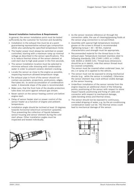
Oxygen Sensor Type Code LSU 4.2 | D 9General Installation Instructions & RequirementsIn general, the sensor installation point must be testedsufficiently by the customer for function and durability. Installation in the exhaust line must be at a pointguaranteeing representative exhaust gas compositionwhilst also satisfying the specified temperature limits The heater power must always be switched on powercontrolled, starting with a maximum ramp up nominalvoltage as described in the sensor specifications. Thisis to reduce thermal stress of the sensor element atcold start due to high peak power in the first seconds. The sensor installation location must be selected tominimise exhaust side stressing with condensationwater in order to prevent ceramic element cracking. Locate the sensor as close to the engine as possible,respecting maximum allowed temperature range. The exhaust pipe in front of the sensor should notcontain any pockets, projections, protrusions, edges,flex-tubes etc. to avoid accumulation of condensationwater. A downside slope of the pipe is recommended. Make sure, that the front hole of the double protectiontube does not point against exhaust gas stream. Never switch on the sensor heating control unit beforeengine start. Delay of sensor heater start or power control of thesensor heater as a function of engine and ambienttemperature. Installation angle should be inclined at least 10 degreestowards horizontal (electrical connection upwards).Thus preventing the collection of liquids betweensensor housing and sensor element during the coldstart phase. Other installation angles must beinspected and tested individually. As the sensor receives reference air through theconnection cable, the use of cleaning/greasing fluids atthe sensor plug connection is not permitted. Assembly with special high temperature resistantgrease on the screw-in thread is recommendedTightening torque = 40 – 60 Nm, materialcharacteristics and strength must be appropriate. Recommended material for the thread boss in theexhaust pipe: Temperature resistant stainless steel tofollowing standards; DIN 17440 1.4301 or 1.4303,SAE 30304 or 30305 (US). Thread boss dimensionsshould be as in sketch, note that sensor thread mustbe covered completely.The sensor must be covered when underseal (wax, taretc.) or spray oil is applied to the vehicle. The sensor must not be exposed to strong mechanicalshocks (e.g. while the sensor is installed). Otherwisethe sensor element may crack without visible damageat the sensor housing. Underfloor installation of the sensor remote from theengine requires an additional check of the followingpoints; positioning of the sensor with respect to stoneimpact hazard; positioning and fixing of cable andconnector with respect to mechanical damage,cable bending stress and thermal stress. The sensor should not be exposed to continuous,one-sided dripping of water, e.g. by the air-conditioningcondensation water out let. The thermal stress couldlead to mechanical damage of the sensor.∅ 25M 18 x 1.5≥10°∅ 23310.5 + 0.352009 | 2010 Bosch Automotive Aftermarket