ST 3000 Smart Pressure Transmitter Series 100 ... - Industrial Controls
ST 3000 Smart Pressure Transmitter Series 100 ... - Industrial Controls
ST 3000 Smart Pressure Transmitter Series 100 ... - Industrial Controls

Create successful ePaper yourself
Turn your PDF publications into a flip-book with our unique Google optimized e-Paper software.
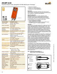
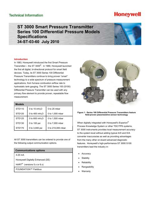
<strong>ST</strong> <strong>3000</strong> <strong>Smart</strong> <strong>Pressure</strong> <strong>Transmitter</strong> 3Operating Conditions – All ModelsParameterAmbient TemperatureReferenceConditionRated Condition Operative Limits Transportation andStorageC F C F C F C F<strong>ST</strong>D110 25±1 77±2 -15 to 65 5 to 150 -40 to 70 -40 to 158 -40 to 70 -40 to 158<strong>ST</strong>D125 25±1 77±2 -40 to 85 -40 to 185 -40 to 85 -40 to 185 -55 to 125 -67 to 257<strong>ST</strong>D120, <strong>ST</strong>D130, <strong>ST</strong>D170 25±1 77±2 -40 to 85 -40 to 185 -40 to 93 -40 to 200 -55 to 125 -67 to 257Meter Body Temperature<strong>ST</strong>D110 25±1 77±2 -15 to 65 5 to 150 -40 to 70 -40 to 158 -40 to 70 -40 to 158<strong>ST</strong>D125 25±1 77±2 -40 to 85 -40 to 185 -40 to 85 -40 to 185 -55 to 125 -67 to 257<strong>ST</strong>D120, <strong>ST</strong>D130, <strong>ST</strong>D170 25±1 77±2 -40 to 110 1 -40 to 230 1 -40 to 125 -40 to 257 -55 to 125 -67 to 257Humidity %RH 10 to 55 0 to <strong>100</strong> 0 to <strong>100</strong> 0 to <strong>100</strong>Vac. Region – Min. <strong>Pressure</strong>All Models Except <strong>ST</strong>D110mmHg absoluteinH 2O absoluteAtmosphericAtmospheric25132 (short term ) 21 (short term ) 2Supply Voltage, Current, andLoad ResistanceMaximum AllowableWorking <strong>Pressure</strong> (MAWP) 4(<strong>ST</strong> <strong>3000</strong> products are rated toMaximum Allowable Working <strong>Pressure</strong>.MAWP depends on Approval Agencyand transmitter materials ofconstruction.)Voltage Range: 10.8 to 42.4 Vdc at terminalsCurrent Range: 3.0 to 21.8 mALoad Resistance: 0 to 1,440 ohms (as shown in Figure 2)<strong>ST</strong>D110 = 50 psi, 3.45 bar<strong>ST</strong>D120, <strong>ST</strong>D125, <strong>ST</strong>D130 and <strong>ST</strong>D170 = 4,500 psi, 310 bar 3Static <strong>Pressure</strong> Limit = Maximum Allowable Working <strong>Pressure</strong> (MAWP) = OverpressureLimit for <strong>ST</strong> <strong>3000</strong> Differential <strong>Pressure</strong> <strong>Transmitter</strong>s1 For CTFE fill fluid, the rating is -15 to 110C (5 to 230F)2 Short term equals 2 hours at 70C (158F)3 MAWP applies for temperature range -40 to 125C. However, Static <strong>Pressure</strong> Limit is de-rated to 3,000 psi from -26C to -40C.Use of graphite o-rings de-rates transmitter to 3,625 psi. Use of adaptor with graphite o-rings de-rates transmitter to 3,000 psi.4 Consult factory for MAWP of <strong>ST</strong> <strong>3000</strong> transmitters with CSA approval.14401200LoopResistance(ohms)800650450Note: A minimum of 250 ohmsof loop resistance is necessaryto support communications.Loop resistance equals barrierresistance plus wire resistanceplus receiver resistance.250= Operating Area0 10.8 16.28 20.63 25 28.3 37.0 42.4Operating Voltage (Vdc)Figure 2 - Supply voltage and loop resistance chart
4 <strong>ST</strong> <strong>3000</strong> <strong>Smart</strong> <strong>Pressure</strong> <strong>Transmitter</strong>Performance Under Rated Conditions* - Model <strong>ST</strong>D110 (0 to 10 inH 2 O)ParameterDescriptionUpper Range LimitMinimum SpaninH 2OmbarinH 2Ombar10 (39.2F/4C is standard reference temperature for inH 2O range.)250.41Turndown Ratio 25 to 1Zero Elevation and Suppression No limit except minimum span within ±<strong>100</strong>% URL.Accuracy (Reference – Includescombined effects of linearity,hysteresis, and repeatability)• Accuracy includes residual errorafter averaging successivereadings.• For FOUNDATION TM Fieldbus useDigital Mode specifications.• For HART ® use Analog Modespecifications.Zero Temperature Effect per28C (50F)Combined Zero and SpanTemperature Effect per 28C(50F)In Analog Mode: ±0.1% of calibrated span or upper range value (URV), whichever isgreater, terminal based.For URV below reference point (1.5 inH 2O), accuracy equals:0.025 0.0751.5 inH 2Ospan inH 2Oor 0.025 0.0753.75 mbarin % of spanspan mbarIn Digital Mode: ±0.0875% of calibrated span or upper range value (URV), whichever isgreater, terminal based.For URV below reference point (1.5 inH 2O), accuracy equals:0.0125 0.0751.5 inH 2Ospan inH 2Oor In Analog Mode: ±0.2625% of span.For URV below reference point (10 inH 2O), effect equals:0.0125 0.2510 inH 2Ospan inH 2Oor In Digital Mode: ±0.25% of span.For URV below reference point (10 inH 2O), effect equals: 0.2510 inH 2Ospan inH 2O 0.0125 0.0753.75 mbarin % of spanspan mbar 0.0125 0.2525 mbarin % of spanspan mbar25 mbaror 0.25 in % of spanspan mbarIn Analog Mode: ±0.4875% of span.For URV below reference point (10 inH 2O), effect equals:0.2375 0.2510 inH 2Ospan inH 2Oor In Digital Mode: ±0.4625% of span.For URV below reference point (10 inH 2O), effect equals:0.2125 0.2510 inH 2Ospan inH 2Oor 0.2375 0.2525 mbarin % of spanspan mbar 0.2125 0.2525 mbarin % of spanspan mbar* Performance specifications are based on reference conditions of 25C (77F), zero (0) static pressure, 10 to 55% RH, and316 Stainless Steel barrier diaphragm.
<strong>ST</strong> <strong>3000</strong> <strong>Smart</strong> <strong>Pressure</strong> <strong>Transmitter</strong> 5Performance Under Rated Conditions* - Model <strong>ST</strong>D120 (0 to 400 inH 2 O)ParameterDescriptionUpper Range LimitinH 2Ombar400 (39.2F/4C is standard reference temperature for inH 2O range.)1,0001 Note: Recommended minimum span in square root mode is 20 inH 2O (50 mbar).2.5Minimum SpaninH 2OmbarTurndown Ratio 400 to 1Zero Elevation andNo limit except minimum span within ±<strong>100</strong>% URL. Specifications valid from -5 toSuppression+<strong>100</strong>% URL.Accuracy (Reference – Includes In Analog Mode: ±0.0525% of calibrated span or upper range value (URV), whichevercombined effects of linearity, is greater, terminal based.hysteresis, and repeatability) For URV below reference point (25 inH 2O), accuracy equals:• Accuracy includes residual errorafter averaging successivereadings.• For FOUNDATION TM Fieldbus useDigital Mode specifications.• For HART ® use Analog Modespecifications.Zero Temperature Effect per28C (50F)Combined Zero and SpanTemperature Effect per 28C(50F)Zero Static <strong>Pressure</strong> Effect per1,000 psi (70 bar)Combined Zero and Span Static<strong>Pressure</strong> Effect per 1,000 psi(70 bar)Stability 25 inH 2 O 62 mbar 0.025 0.0275or 0.025 0.0275 span inH2O in % of span span mbar In Digital Mode: ±0.0375% of calibrated span or upper range value (URV), whicheveris greater, terminal based.For URV below reference point (25 inH 2O), accuracy equals: 25 inH 2 O 62 mbar 0.0125 0.025or 0.0125 0.025 span inH2O in % of span span mbar * For High Accuracy (HA) option: ±0.025% of calibrated span or upper range value(URV), whichever is greater, terminal based.In Analog Mode: ±0.0625% of span.For URV below reference point (50 inH 2O), effect equals: 50 inH 2 O 125 mbar 0.0125 0.05or 0.0125 0.05 in % of span span inH 2O span mbar In Digital Mode: ±0.05% of span.For URV below reference point (50 inH 2O), effect equals: 0.0550inHspan inH2 O or2O 125 mbar 0.05 in % of span span mbar In Analog Mode: ±0.10% of span.For URV below reference point (50 inH 2O), effect equals: 50 inH 2 O 125 mbar 0.05 0.05or 0.05 0.05 in % of span span inH2O span mbar In Digital Mode: ±0.075% of span.For URV below reference point (50 inH 2O), effect equals:0.025 0.0550 inH2 Oor span inH2O 125 mbar 0.025 0.05 in % of span span mbar ±0.075% of span.For URV below reference point (50 inH 2O), effect equals: 50 inH 2 O 0.0125 0.0625or 125 mbar 0.0125 0.0625 in % of span span inH2O span mbar ±0.15% of span.For URV below reference point (50 inH 2O), effect equals: 50 inH 2 O 0.0875 0.0625or 125 mbar 0.0875 0.0625 in % of span span inH2O span mbar ±0.01% of URL per year for lifetime* Performance specifications are based on reference conditions of 25C (77F), zero (0) static pressure, 10 to 55% RH, and 316 StainlessSteel barrier diaphragm.
6 <strong>ST</strong> <strong>3000</strong> <strong>Smart</strong> <strong>Pressure</strong> <strong>Transmitter</strong>Performance Under Rated Conditions* - Model <strong>ST</strong>D125 (0 to 600 inH 2 O)ParameterDescriptionUpper Range LimitMinimum SpaninH 2OmbarinH 2 Ombar600 (39.2F/4C is standard reference temperature for inH 2O range.)1,5002562.2Turndown Ratio <strong>100</strong> to 1Zero Elevation and Suppression No limit except minimum span within 0 to <strong>100</strong>% URL.Accuracy (Reference – Includes In Analog Mode: ±0.075% of calibrated span or upper range value (URV), whichever iscombined effects of linearity, greater, terminal based.hysteresis, and repeatability) For URV below reference point (25 inH 2O), accuracy equals:• Accuracy includes residual errorafter averaging successive 25 inH 2 O 0.0375 0.0375readings.or 62 mbar 0.0375 0.0375 in % of span span inH O • For FOUNDATION TM 2 span mbar Fieldbus useIn Digital Mode: ±0.05% of calibrated span or upper range value (URV), whichever isDigital Mode specifications.greater, terminal based.• For HART ® use Analog ModeFor URV below reference point (25 inHspecifications.2O), accuracy equals: 25 inH 2 O 0.0125 0.0375or 62 mbar 0.0125 0.0375 in % of span span inH2O span mbar Zero Temperature Effect per In Analog Mode: ±0.0625% of span.28C (50F)For URV below reference point (50 inH 2O), effect equals: 50 inH 2 O 0.0125 0.05or 125 mbar 0.0125 0.05 in % of span span inH2O span mbar In Digital Mode: ±0.05% of span.For URV below reference point (50 inH 2O), effect equals: 50 inH2 O 125 mbar 0.05 or 0.05 in % of span span inH2O span mbar Combined Zero and Span In Analog Mode: ±0.10% of span.Temperature Effect per 28C For URV below reference point (50 inH 2O), effect equals:(50F) 50 inH 2 O 0.05 0.05or 125 mbar 0.05 0.05 in % of span span inH2O span mbar In Digital Mode: ±0.075% of span.For URV below reference point (50 inH 2O), effect equals: 50 inH 2 O 0.025 0.05or 125 mbar 0.025 0.05 in % of span span inH2O span mbar Zero Static <strong>Pressure</strong> Effect per ±0.075% of span.1,000 psi (70 bar)For URV below reference point (50 inH 2O), effect equals: 50 inH 2 O 0.0125 0.0625or 125 mbar 0.0125 0.0625 in % of span span inH2O span mbar Combined Zero and Span Static ±0.20% of span.<strong>Pressure</strong> Effect per 1,000 psi (70 For URV below reference point (50 inH 2O), effect equals:bar) 50 inH 2 O 0.1375 0.0625or 125 mbar 0.1375 0.0625 in % of span span inH2O span mbar Stability±0.015% URL per year* Performance specifications are based on reference conditions of 25C (77F), zero (0) static pressure, 10 to 55% RH, and316 Stainless Steel barrier diaphragm.
<strong>ST</strong> <strong>3000</strong> <strong>Smart</strong> <strong>Pressure</strong> <strong>Transmitter</strong> 7Performance Under Rated Conditions* - Model <strong>ST</strong>D130 (0 to <strong>100</strong> psi)ParameterDescriptionUpper Range LimitMinimum Spanpsibarpsibar<strong>100</strong>750.35Turndown Ratio <strong>100</strong> to 1Zero Elevation and Suppression No limit except minimum span within –18 and +<strong>100</strong>% URL. Specifications valid from –5to +<strong>100</strong>% URL.Accuracy (Reference – Includescombined effects of linearity,hysteresis, and repeatability)• Accuracy includes residual errorafter averaging successivereadings.• For FOUNDATION TM Fieldbus useDigital Mode specifications.• For HART ® use Analog Modespecifications.Zero Temperature Effect per28C (50F)Combined Zero and SpanTemperature Effect per 28C(50F)Zero Static <strong>Pressure</strong> Effect per1,000 psi (70 bar)Combined Zero and Span Static<strong>Pressure</strong> Effect per 1,000 psi (70bar)StabilityIn Analog Mode: ±0.075% of calibrated span or upper range value (URV), whichever isgreater, terminal based.For URV below reference point (15 psi), accuracy equals: 15 psi 0.025 0.05or 1 bar 0.025 0.05 in % of span span psi span bar In Digital Mode: ±0.0625% of calibrated span or upper range value (URV), whichever isgreater, terminal based.For URV below reference point (15 psi), accuracy equals: 15 psi 0.0125 0.05or 1 bar 0.0125 0.05 in % of span span psi span bar In Analog Mode: ±0.0625% of span.For URV below reference point (30 psi), effect equals: 30 psi 0.0125 0.05or 2 bar 0.0125 0.05 in % of span span psi span bar In Digital Mode: ±0.05% of span.For URV below reference point (30 psi), effect equals: 30 psi 2 bar 0.05 or 0.05 in % of span span psi span bar In Analog Mode: ±0.10% of span.For URV below reference point (30 psi), effect equals: 30 psi 0.05 0.05or 2 bar 0.05 0.05 in % of span span psi span bar In Digital Mode: ±0.075% of span.For URV below reference point (30 psi), effect equals: 30 psi 0.025 0.05or 2 bar 0.025 0.05 in % of span span psi span bar ±0.075% of span.For URV below reference point (30 psi), effect equals: 30 psi 0.0125 0.0625or 2 bar 0.0125 0.0625 in % of span span psi span bar ±0.15% of span.For URV below reference point (30 psi), effect equals: 30 psi 0.0875 0.0625or 2 bar 0.0875 0.0625 in % of span span psi span bar ±0.04% of URL per year.* Performance specifications are based on reference conditions of 25C (77F), zero (0) static pressure, 10 to 55% RH, and316 Stainless Steel barrier diaphragm.
8 <strong>ST</strong> <strong>3000</strong> <strong>Smart</strong> <strong>Pressure</strong> <strong>Transmitter</strong>Performance Under Rated Conditions* - Model <strong>ST</strong>D170 (0 to 3,000 psi)ParameterDescriptionUpper Range LimitMinimum Spanpsibarpsibar3,000210<strong>100</strong>7Turndown Ratio <strong>100</strong> to 1Zero Elevation and Suppression No limit except minimum span within –0.6 and +<strong>100</strong>% URL. Specifications valid overthis range.Accuracy (Reference – Includes In Analog Mode: ±0.15% of calibrated span or upper range value (URV), whichever iscombined effects of linearity, greater, terminal based.hysteresis, and repeatability) For URV below reference point (300 psi), accuracy equals:• Accuracy includes residual errorafter averaging successive 300 psi 0.05 0.10or 21 bar readings.0.05 0.10 in % of span span psi span bar • For FOUNDATION TM Fieldbus useIn Digital Mode: ±0.125% of calibrated span or upper range value (URV), whichever isDigital Mode specifications.greater, terminal based.• For HART ® use Analog ModeFor URV below reference point (300 psi), accuracy equals:specifications. 300 psi 0.025 0.10or 21 bar 0.025 0.10 in % of span span psi span bar Zero Temperature Effect per In Analog Mode: ±0.1125% of span.28C (50F)For URV below reference point (500 psi), effect equals: 500 psi 0.0125 0.10or 35 bar 0.0125 0.10 in % of span span psi span bar In Digital Mode: ±0.10% of span.For URV below reference point (500 psi), effect equals: 500 psi 35 bar 0.10 or 0.10 in % of span span psi span bar Combined Zero and Span In Analog Mode: ±0.175% of span.Temperature Effect per 28C For URV below reference point (500 psi), effect equals:(50F) 500 psi 0.075 0.10or 35 bar 0.075 0.10 in % of span span psi span bar In Digital Mode: ±0.15% of span.For URV below reference point (500 psi), effect equals: 500 psi 0.05 0.10or 35 bar 0.05 0.10 in % of span span psi span bar Zero Static <strong>Pressure</strong> Effect per ±0.075% of span.1,000 psi (70 bar)For URV below reference point (500 psi), effect equals: 500 psi 0.0125 0.0625or 35 bar 0.0125 0.0625 in % of span span psi span bar Combined Zero and Span Static ±0.15% of span.<strong>Pressure</strong> Effect per 1,000 psi (70 For URV below reference point (500 psi), effect equals:bar) 500 psi 0.0875 0.0625or 35 bar 0.0875 0.0625 in % of span span psi span bar Stability±0.03% of URL per year.* Performance specifications are based on reference conditions of 25C (77F), zero (0) static pressure, 10 to 55% RH, and316 Stainless Steel barrier diaphragm.
<strong>ST</strong> <strong>3000</strong> <strong>Smart</strong> <strong>Pressure</strong> <strong>Transmitter</strong> 9Performance Under Rated Conditions – All ModelsParameterDescriptionOutput (two-wire)Analog : 4 to 20 mA (Normal signal range is ≥ 3.8 mA and ≤ 20.8 mA. <strong>Transmitter</strong> failurevalues are: is ≥ 3.6 mA and ≤ 20.9 mADigital communications : Honeywell DE mode, FOUNDATION TM Fieldbus or HART ® protocol (selectable versions 5.x or 6.xavailable).Supply Voltage EffectDamping Time ConstantNAMUR NE 43 Compliance(Option “NE”)SIL 2/3 Compliance(Option “SL”)Lightning Protection Option(Option “LP”)0.005% span per volt.Adjustable from 0 to 32 seconds digital damping.<strong>Transmitter</strong> failure information is generated when the measuring information is invalid or no longerpresent. Failure information is transmitted as a current signal but outside the normal 4-20 mAmeasurement signal level. <strong>Transmitter</strong> failure values are: ≤ 3.6 mA and ≥ 21.0 mA. The normalsignal range is ≥ 3.8 mA and ≤ 20.5 mA.SIL certified to IEC 61508 for non-redundant use in SIL 2 related Safety Systems (single use)and for redundant (multiple) use in SIL 3 Safety Systems throughTÜV Nord Sys Tec GmbH & Co. KG under the following standards: IEC61508-1: 1998; IEC61508-2: 2000; IEC61508-3: 1998.Leakage Current: 10 microamps max. @ 42.4 VDC, 93°CImpulse Rating: 10/20 µ sec. 5,000 Amps (50 strikes) 10,000 Amps (20 strikes)(rise/decay) 10/1,000 µ sec. 250 Amps (1,000 strikes) 500 Amps (400 strikes)Physical and Approval BodiesParameterBarrier Diaphragms Material<strong>ST</strong>D125, <strong>ST</strong>D110<strong>ST</strong>D120, <strong>ST</strong>D130, <strong>ST</strong>D170Process Head Material<strong>ST</strong>D125, <strong>ST</strong>D110<strong>ST</strong>D120, <strong>ST</strong>D130, <strong>ST</strong>D170Description316L SS, Gold-plated 316L SS316L SS, Hastelloy ® C-276 2 , Monel ® 400 3 , Tantalum, Gold-plated 316L SS, Gold-platedHastelloy ® C-276, Gold-plated Monel ® 400316 SS 4 , Carbon Steel (Zinc-plated) 5316 SS 4 , Carbon Steel (Zinc-plated) 5 , Hastelloy ® C-276 6 , Monel ® 400 7Vent/Drain Valves & Plugs 1 316 SS 4 , Hastelloy ® C-276 2 , Monel ® 400 8Head GasketsMeter Body BoltingOptional Adapter Flange and BoltsMounting BracketFill FluidElectronic HousingMountingProcess ConnectionsWiringDimensions See Figure 4.Glass-filled PTFE standard. Viton ® and graphite are optional. See MSG.Carbon Steel (Zinc plated) standard. Options include 316 SS, NACE A286 SS bolts and 304 SSnuts and B7M.Adapter Flange materials include 316 SS, Hastelloy ® C-276 and Monel ® 400. Bolt material forflanges is dependent on process head bolts material chosen. Standard adaptor o-ring material isglass-filled PTFE. Viton ® and graphite are optional.Carbon Steel (Zinc-plated) or Stainless Steel bracket or Carbon Steel flat bracket available(standard options).Silicone DC ® 200 oil or CTFE (Chlorotrifluoroethylene).Note that Model <strong>ST</strong>D110 is only available with silicone fill fluid.Epoxy-Polyester hybrid paint. Low Copper-Aluminum. Meets NEMA 4X (watertight) and NEMA 7(explosion proof). All stainless steel housing is optional.Can be mounted in virtually any position using the standard mounting bracket. Bracket isdesigned to mount on 2-inch (50 mm) vertical or horizontal pipe. See Figure 3.1/4-inch NPT; 1/2-inch NPT with adapter (standard option, meets DIN requirements)Accepts up to 16 AWG (1.5 mm diameter).Net Weight9.0 pounds (4.1 Kg).1 Vent/Drains are sealed with Teflon ® or PTFE2 Hastelloy ® C-276 or UNS N102763Monel ® 400 or UNS N044004 Supplied as 316 SS or as Grade CF8M, the casting equivalent of 316 SS.5Carbon Steel heads are zinc-plated and not recommended for water service due to hydrogen migration. For that service, use 316 stainless steel wettedProcess Heads.6 Hastelloy ® C-276 or UNS N10276. Supplied as indicated or as Grade CW12MW, the casting equivalent of Hastelloy ® C-2767 Monel ® 400 or UNS N04400. Supplied as indicated or as Grade M30C, the casting equivalent of Monel ® 4008 Monel 400 ® or UNS N04400 or UNS N04405
<strong>ST</strong> <strong>3000</strong> <strong>Smart</strong> <strong>Pressure</strong> <strong>Transmitter</strong> 11Type of Protection Comm. Option Field Parameters Temp. CodesCanadianStandardsAssociation(CSA)Explosion Proof: Class I, Division1, Groups B, C, D locationsDust Ignition Proof: Class II, III,Division 1, Groups E, F, Glocations,Enclosure Type 4XIntrinsically Safe:Class I, II, III, Division 1, Groups A,B, C, D, E, F, G locations,Enclosure Type 4XNonincendive:Class I, Division 2, Groups A, B, C,D locations, Enclosure Type 4XCanadian Registration Number(CRN):All All T4 Ta = 93ºC4-20 mA / DE4-20 mA / HARTFieldbus – Entity(Not FISCO)4-20 mA / DE4-20 mA / HARTFieldbus – Entity(Not FNICO)Vmax = 42VImax = 225mACi = 4.2nFLi = *Pi =1.2WVmax = 42VImax = 225mACi = 4.2nFLi = *Pi =1.2WVmax = 24VImax = 250mACi = 4.2nFLi = 0Pi =1.2WVmax = 42.4VImax = 225mACi = 4.2nFLi = *Pi =1.2WVmax = 30VImax = 225mACi = 4.2nFLi = *Pi =1.2WVmax = 24VImax = 250mACi = 4.2nFLi = 0Pi =1.2WT4 Ta = 93ºCT4 Ta = 93ºCT4 Ta = 40ºCT3 Ta = 93ºCT4 Ta = 93ºCT4 Ta = 93ºCT4 Ta = 40ºCT3 Ta = 93ºCAll <strong>ST</strong> <strong>3000</strong> models except <strong>ST</strong>G19L, <strong>ST</strong>G99L, <strong>ST</strong>G170 and <strong>ST</strong>G180have been registered in all provinces and territories in Canada and aremarked CRN: 0F8914.5C.
12 <strong>ST</strong> <strong>3000</strong> <strong>Smart</strong> <strong>Pressure</strong> <strong>Transmitter</strong>Type of Protection Comm. Option Field Parameters Temp. CodesIECExInternationalElectrotechnicalCommission(LCIE)Flameproof, Zone 1:Ex d IIC, Enclosure IP 66/67Intrinsically Safe, Zone 0/1:Ex ia IIC, Enclosure IP 66/67* Li = 0 except Li = 150µH when Option ME, Analog Meter, is selected.All4-20 mA / DE4-20 mA / HARTFieldbus(Not FISCO)AllUi = 30VIi = <strong>100</strong>mACi = 4.2nFLi = *Pi =1.2WUi = 30VIi = <strong>100</strong>mACi = 4.2nFLi = *Pi =1.2WUi = 24VIi = 250mACi = 4.2nFLi = 0Pi =1.2WT5 Ta = –50 to 93ºCT6 Ta = –50 to 78ºCT4 Ta = –50 to 93ºCT5 Ta = –50 to 85ºCT6 Ta = –50 to 70ºCT4 Ta = –50 to 93ºCT5 Ta = –50 to 63ºCT6 Ta = –50 to 48ºCT3 Ta = –50 to 93ºCT4 Ta = –50 to 40ºCSAEx(South Africa)Type of Protection Comm. Option Field Parameters Temp. CodesFlameproof, Zone 1:Ex d IIC, Enclosure IP 66/67Intrinsically Safe, Zone 0/1:Ex ia IIC, Enclosure IP 66/67Multiple Marking:Flameproof, Zone 1:Ex d IIC, Enclosure IP 66/67Intrinsically Safe, Zone 0/1:Ex ia IIC, Enclosure IP 66/67The user must determine the type ofprotection required for installation ofthe equipment. The user shall thencheck the box [√] adjacent to the typeof protection used on the equipmentcertification nameplate. Once a typeof protection has been checked on thenameplate, subsequently theequipment shall not be reinstalledusing any of the other certificationtypes.* Li = 0 except Li = 150µH when Option ME, Analog Meter, is selected.All4-20 mA / DE4-20 mA / HARTFieldbus(Not FISCO)4-20 mA / DE4-20 mA / HARTFieldbus(Not FISCO)AllUi = 30VIi = <strong>100</strong>mACi = 4.2nFLi = *Pi =1.2WUi = 30VIi = <strong>100</strong>mACi = 4.2nFLi = *Pi =1.2WUi = 24VIi = 250mACi = 4.2nFLi = 0Pi =1.2WUi = 30VIi = <strong>100</strong>mACi = 4.2nFLi = *Pi =1.2WUi = 30VIi = <strong>100</strong>mACi = 4.2nFLi = *Pi =1.2WUi = 24VIi = 250mACi = 4.2nFLi = 0Pi =1.2WT5 Ta = –50 to 93ºCT6 Ta = –50 to 78ºCT4 Ta = –50 to 93ºCT5 Ta = –50 to 85ºCT6 Ta = –50 to 70ºCT4 Ta = –50 to 93ºCT5 Ta = –50 to 63ºCT6 Ta = –50 to 48ºCT3 Ta = –50 to 93ºCT4 Ta = –50 to 40ºCT4 Ta = –50 to 93ºCT5 Ta = –50 to 85ºCT6 Ta = –50 to 70ºCT4 Ta = –50 to 93ºCT5 Ta = –50 to 63ºCT6 Ta = –50 to 48ºCT3 Ta = –50 to 93ºCT4 Ta = –50 to 40ºC
<strong>ST</strong> <strong>3000</strong> <strong>Smart</strong> <strong>Pressure</strong> <strong>Transmitter</strong> 13Type of Protection Comm. Option Field Parameters Temp. CodesFlameproof, Zone 0:, Ex tDEnclosure IP 66/67AllAllA20 IP6X T95ºC Ta =93ºC or T80ºC Ta = 78ºCFlameproof, Zone 1:, Ex d IIC, Ex tDEnclosure IP 66/67AllAllT5 Ta = –50 to +93ºCT6 Ta = –50 to +78ºC,A21 IP6X T95ºC Ta =93ºC or T80ºC Ta = 78ºCIntrinsically Safe, Zone 0/1:, Ex ia IIC,Enclosure IP 66/674-20 mA / DE4-20 mA / HARTUi = 30VIi = <strong>100</strong>mACi = 4.2nFLi = *Pi =1.2WUi = 30VIi = <strong>100</strong>mACi = 4.2nFLi = *Pi =1.2WT4 Ta = –50 to 93ºCT5 Ta = –50 to 85ºCT6 Ta = –50 to 70ºCT4 Ta = –50 to 93ºCT5 Ta = –50 to 63ºCT6 Ta = –50 to 48ºCFieldbus(Not FISCO)Ui = 24VIi = 250mACi = 4.2nFLi = 0Pi =1.2WT3 Ta = –50 to 93ºCT4 Ta = –50 to 40ºC4-20 mA / DEUi = 30VIi = <strong>100</strong>mACi = 4.2nFLi = *Pi =1.2WT4 Ta = –50 to 93ºCT5 Ta = –50 to 85ºCT6 Ta = –50 to 70ºCATEX(LCIE)Non-Sparking, Zone 2:,Ex nA IIC (Honeywell),Enclosure IP 66/674-20 mA / HARTUi = 30VIi = <strong>100</strong>mACi = 4.2nFLi = *Pi =1.2WT4 Ta = –50 to 93ºCT5 Ta = –50 to 63ºCT6 Ta = –50 to 48ºCFieldbus(Not FNICO)Ui = 24VIi = 250mACi = 4.2nFLi = 0Pi =1.2WT3 Ta = –50 to 93ºCT4 Ta = –50 to 40ºCMultiple Marking:Flameproof, Zone 1:, Ex d IIC4-20 mA / DEUi = 30VIi = <strong>100</strong>mACi = 4.2nFLi = *Pi =1.2WT4 Ta = –50 to 93ºCT5 Ta = –50 to 85ºCT6 Ta = –50 to 70ºCIntrinsically Safe, Zone 0/1:, Ex ia IICNon-Sparking, Zone 2:, Ex nA IIC4-20 mA / HARTUi = 30VIi = <strong>100</strong>mACi = 4.2nFLi = *Pi =1.2WT4 Ta = –50 to 93ºCT5 Ta = –50 to 63ºCT6 Ta = –50 to 48ºCNOTE: The user must determine thetype of protection required forinstallation of the equipment. Theuser shall then check the box [ √ ]adjacent to the type of protectionused on the equipment certificationnameplate. Once a type ofprotection has been checked on thenameplate, subsequently theequipment shall not be reinstalledusing any of the other certificationtypes.* Li = 0 except Li = 150µH when Option ME, Analog Meter, is selected.Fieldbus(Not FISCO/FNICO)Ui = 24VIi = 250mACi = 4.2nFLi = 0Pi =1.2WT3 Ta = –50 to 93ºCT4 Ta = –50 to 40ºC
14 <strong>ST</strong> <strong>3000</strong> <strong>Smart</strong> <strong>Pressure</strong> <strong>Transmitter</strong>INMETRO(CERTUSP)BrazilType of Protection Comm. Option Field Parameters Temp. CodesFlameproof, Zone 1:BR-Ex d IICEnclosure IP 66/67AllAllT5 Ta = –50 to 93ºCT6 Ta = –50 to 78ºCIntrinsically Safe, Zone 0/1:BR-Ex ia IICEnclosure IP 66/67* Li = 0 except Li = 150µH when Option ME, Analog Meter, is selected.4-20 mA / DE4-20 mA / HARTFieldbus(Not FISCO)Ui = 30VIi = <strong>100</strong>mACi = 4.2nFLi = *Pi =1.2WUi = 30VIi = <strong>100</strong>mACi = 4.2nFLi = *Pi =1.2WUi = 24VIi = 250mACi = 4.2nFLi = 0Pi =1.2WT4 Ta = –50 to 93ºCT5 Ta = –50 to 85ºCT6 Ta = –50 to 70ºCT4 Ta = –50 to 93ºCT5 Ta = –50 to 63ºCT6 Ta = –50 to 48ºCT3 Ta = –50 to 93ºCT4 Ta = –50 to 40ºCThis certificate defines the certifications covered for the <strong>ST</strong> <strong>3000</strong> <strong>Pressure</strong> <strong>Transmitter</strong> family ofproducts, including the SMV <strong>3000</strong> <strong>Smart</strong> Multivariable <strong>Transmitter</strong>. It represents the compilation ofthe five certificates Honeywell currently has covering the certification of these products into marineapplications.For <strong>ST</strong> <strong>3000</strong> <strong>Smart</strong> <strong>Pressure</strong> <strong>Transmitter</strong> and SMV <strong>3000</strong> <strong>Smart</strong> Multivarible <strong>Transmitter</strong><strong>ST</strong> <strong>3000</strong> <strong>Pressure</strong><strong>Transmitter</strong> MarineCertificate(MT Option)American Bureau of Shipping (ABS) - 2009 Steel Vessel Rules 1-1-4/3.7, 4-6-2/5.15, 4-8-3/13 &13.5, 4-8-4/27.5.1, 4-9-7/13. Certificate number: 04-HS417416-PDABureau Veritas (BV) - Product Code: 389:1H. Certificate number: 12660/B0 BVDet Norske Veritas (DNV) - Location Classes: Temperature D, Humidity B, Vibration A, EMC B,Enclosure C. For salt spray exposure; enclosure of 316 S<strong>ST</strong> or 2-part epoxy protection with 316S<strong>ST</strong> bolts to be applied. Certificate number: A-11476Korean Register of Shipping (KR) - Certificate number: LOX17743-AE001Lloyd's Register (LR) - Certificate number: 02/60001(E1) & (E2)
<strong>ST</strong> <strong>3000</strong> <strong>Smart</strong> <strong>Pressure</strong> <strong>Transmitter</strong> 15The <strong>ST</strong> <strong>3000</strong> <strong>Smart</strong> <strong>Pressure</strong> <strong>Transmitter</strong>s are in conformity with the essential requirements of the <strong>Pressure</strong>Equipment Directive.European<strong>Pressure</strong>EquipmentDirective (PED)(97/23/EC)Honeywell <strong>ST</strong> <strong>3000</strong> <strong>Smart</strong> <strong>Pressure</strong> <strong>Transmitter</strong>s are designed and manufactured in accordance with theapplicable portions of Annex I, Essential Safety Requirements, and sound engineering practices. Thesetransmitters have no pressurized internal volume, or have a pressurized internal volume rated less than 200 bar(2,900 psig), and/or have a maximum volume of less than 0.1 liter (Article 3, 1.1.(a) first indent, Group 1 fluids).Therefore, these transmitters are not subject to the essential requirements of the directive 97/23/EC (PED,Annex I) and shall not have the CE mark applied.For transmitters rated > 200 bar (2,900 psig) < 1,000 bar (14,500 psig) Honeywell maintains a technical file inaccordance with Annex III, Module A, (internal production control) when the CE mark is required. <strong>Transmitter</strong>Attachments: Diaphragm Seals, Process Flanges and Manifolds comply with Sound Engineering Practice.NOTE: <strong>Pressure</strong> transmitters that are part of safety equipment for the protection of piping (systems) orvessel(s) from exceeding allowable pressure limits, (equipment with safety functions in accordance with<strong>Pressure</strong> Equipment Directive 97/23/EC article 1, 2.1.3), require separate examination.A formal statement from TÜV Industry Service Group of TÜV America, Inc., a division of TÜV Süddeutschland,a Notified Body regarding the <strong>Pressure</strong> Equipment Directive, can be found at www.honeywell.com. A hardcopy may be obtained by contacting a Honeywell representative.CE MarkElectro Magnetic Compatibility (EMC) (2004/108/EC)All Models: EN 50081-1: 1992; EN 50082-2:1995; EN 61326-1:1997 + A1, A2, and A3 – <strong>Industrial</strong> LocationsDual SealCertificationRecommendedFrequency ofCalibrationApprovedManufacturingLocationsDual Seal Certification based on ANSI/NFPA 70-202 and ANSI/ISA 12.27.01 requirements without the use ofadditional seal protection elements.Honeywell recommends verifying the calibration of these devices once every four years.Honeywell Process Solutions - York, PA USAHoneywell (Tianjin) Limited – Tianjin, P.R. ChinaHoneywell Automation India Ltd. – Pune 411013 IndiaFoundation TM Fieldbus is a trademark of the Fieldbus Foundation.Viton ® is a registered trademark of DuPontHART ® is a registered trademark of HART Communications Foundation. Teflon ® is a registered trademark of DuPont.Hastelloy ® C-276 is a registered trademark of Haynes International.DC ® 200 is a registered trademark of Dow Corning.Monel ® 400 is a registered trademark of Special Metals Corporation.FM Approvals SM is a service mark of FM Global<strong>ST</strong> <strong>3000</strong> and Experion are registered trademarks of Honeywell International Inc.
16 <strong>ST</strong> <strong>3000</strong> <strong>Smart</strong> <strong>Pressure</strong> <strong>Transmitter</strong>MountingFigure 3 – Examples of typical mounting positionsReference Dimensions: millimetersinchesFigure 4 – Typical mounting dimensions of <strong>ST</strong>D110, <strong>ST</strong>D120, <strong>ST</strong>D125, <strong>ST</strong>D130 & <strong>ST</strong>D170 for reference
<strong>ST</strong> <strong>3000</strong> <strong>Smart</strong> <strong>Pressure</strong> <strong>Transmitter</strong> 17Options High Accuracy (Option HA)Extends applicable S<strong>100</strong> models to ±0.025% analogreference accuracy. Mounting Bracket (Options MB, MX, SB, SX, FB)The mounting bracket is available in either zinc-platedcarbon steel or stainless steel and is suitable forhorizontal or vertical mounting on a two inch (50millimeter) pipe, as well as wall mounting. An optionalflat mounting bracket is also available in carbon steel fortwo inch (50 millimeter) pipe mounting. An option alsoexists for Marine approved mounting brackets used withMarine certification options. Indicating Meter (Options ME and SM)Two integral meter options are available. An analogmeter (option ME) is available with a dual 0 to 10 squareroot and 0 to <strong>100</strong>% linear scale. The <strong>Smart</strong> Meter(option SM) provides an LCD display for both analogand digital output and can be configured to displaypressure in selected engineering units. HART ® Output Protocol (Options HC and H6)Optional electronic modules for the <strong>ST</strong> <strong>3000</strong> provideHART ® Protocol compatibility in either HART ® 5.x or 6.xformats. <strong>Transmitter</strong>s with a HART ® Option arecompatible with any HART ® enabled system thatprovides 5.x or 6.x format support. Digital Enhanced Output (Option DE)A communications protocol used together with TDC andExperion system solutions to provide a higher level andmore secure data interface between instruments and thecontrol system.Lightning Protection (Option LP)A terminal block is available with circuitry that protectsthe transmitter from transient surges induced by nearbylightning strikes.NAMUR NE43 Compliance (Option NE)This option provides software the meets the NAMURNE43 requirements for failsafe software. <strong>Transmitter</strong>failure information is generated when the measuringinformation is no longer valid.<strong>Transmitter</strong> failure values are ≤ 3.6 mA and ≥ 21.0 mA.The normal <strong>ST</strong> <strong>3000</strong> ranges are ≤ 3.8 mA and ≥ 20.8 mA.Write Protection (Options WP and WX)Provides the capability to hardwire write-protectinstalled transmitter configurations.Stainless Steel Tagging (Option TG)Up to 30 characters can be added on the stainlesssteel nameplate mounted on the transmitter’selectronics housing at no extra cost. A stainless steelwired on tag with additional data of up to 4 lines of 28characters is also available. The number of charactersfor tagging includes spaces.<strong>Transmitter</strong> Configuration (Options TC and FC)With Option TC, the factory can configure the analog,DE or HART ® transmitter’s linear/square rootextraction, damping time, LRV, URV and mode(analog/digital) and enter an ID tag of up to eightcharacters and scratchpad information as specified.With Option FC, the Device ID, <strong>Transmitter</strong> Tag, UnitLevel Node Address, Output Mode and Damping TimeConstants can be specified.Foundation TM Fieldbus Output (Option FF)Equips transmitter with FF protocol for use in 31.25kbit/s FF networks. See document 34-<strong>ST</strong>-03-72 foradditional information on <strong>ST</strong> <strong>3000</strong> Fieldbus transmitters.Custom Calibration and ID in Memory (Option CC)The factory can calibrate any range within the scope ofthe transmitter’s range and enter an ID tag of up toeight characters in the transmitter’s memory.SIL2/SIL3 Certification (Option SL)This <strong>ST</strong> <strong>3000</strong> product is available for use with safetyIndicator Configuration (Option CI)Provides custom configuration of <strong>Smart</strong> Meterssystems. With the SL option, we are fully certified to SIL2 capability for single transmitters and SIL 3 capabilityfor multiple transmitter use through TÜV Nord Sys TecGmbH & Co. KG. We are in compliance with thefollowing SIL standards:Lifetime Warranty (Option WL)Extends limited 1-year warranty policy to 15 years for<strong>ST</strong> <strong>3000</strong> S<strong>100</strong> pressure transmitters. See HoneywellTerms and Conditions.IEC 61508-1: 1998;IEC 61508-2: 2000;IEC 61508-3: 1998
18 <strong>ST</strong> <strong>3000</strong> <strong>Smart</strong> <strong>Pressure</strong> <strong>Transmitter</strong>Ordering informationFor application assistance, current specifications, pricing, or name of the nearest Authorized Distributor, contact one of theoffices below. Or, visit Honeywell on the World Wide Web at: http://www.honeywell.com.ASIA PACIFICControl ProductsAsia Pacific HeadquartersPhone: +(65) 6355-2828Fax: +(65) 6445-3033Asia Pacific GlobalTechnical SupportField InstrumentsPhone: +65 6580 3156Fax: +65 6445-3033Process InstrumentsPhone: (603) 76950 4777Fax: (603) 7958 8922AustraliaHoneywell LimitedPhone: +(61) 7-3846 1255FAX: +(61) 7-3840 6481Toll Free 1300-36-39-36Toll Free Fax:1300-36-04-70China – PRC - BeijingHoneywell China Inc.Phone: +(86-10) 8458-3280Fax: +(86-10) 8458-4650China – PRC - ShanghaiHoneywell China Inc.Phone: (86-21) 5257-4568Fax: (86-21) 6237-2826China – PRC - ChengduHoneywell China Inc.Phone: +(86-28) 8678-6348Fax: +(86-28) 8678-7061China – PRC - Xi’anHoneywell China Ltd - Xi’an.Phone: +(86-29) 8833-7490Fax: +(86-29) 8833-7489China – PRC - Shenzhen-Honeywell China Inc.Phone: +(86) 755-2518-1226Fax: +(86) 755-2518-1221IndonesiaPT Honeywell IndonesiaPhone: +(62) 21-535-8833FAX: +(62) 21-5367 <strong>100</strong>8IndiaAutomation India Ltd.Honeywell Ltd.Phone:+(91) 5603-9400Fax: +(91) 5603-9600JapanHoneywell Inc.Phone: +(81) 3 6730 7150Fax: +(81) 3 6730 7228MalaysiaHoneywell EngineeringSdn BhdPhone: +(60-3) 7950-4776Fax: +(60-3) 7958-8922New ZealandHoneywell LimitedPhone: +(64-9) 623-5052Fax: +(64-9) 623-5060Toll Free (0800) 202-088PhilippinesHoneywell Systems(Philippines) Inc.Phone: +(63-2) 633-2830-31/636 1661-62Fax: +(63-2) 638-4013SingaporeHoneywell Pte Ltd.Phone: +(65) 6580 3278Fax: +(65) 6445-3033South KoreaHoneywell Korea Co LtdPhone: +(822) 799 6315Fax: +(822) 792 9015ThailandHoneywell Systems(Thailand) Ltd.Phone: +(662) 693-3099FAX: +(662) 693-3089Taiwan R.O.C.Honeywell Taiwan Ltd.Phone: +(886-2) 2245-<strong>100</strong>0FAX: +(886-2) 2245-3241SE Asia Countriessee Honeywell Pte Ltd(Singapore)for:PakistanCambodiaGuamLaosMyanmarVietnamEast TimorSE Asia Countriessee Honeywell AutomationIndia Ltd for:BangladeshNepalSri LankaEUROPEAustriaHoneywell Austria GmbHPhone: +43 (316)400123FAX: +43 (316)40017BelgiumHoneywell SA/NVPhone: +32 (0) 2 728 24 07FAX: +32 (0) 2 728 22 45BulgariaHoneywell EOODPhone: +(359) 2 40 20 900FAX: +(359) 2 40 20 990Czech RepublicHoneywell spol. s.r.o.Phone: +420 242 442 232FAX: +420 242 442 131DenmarkHoneywell A/SPhone: +(45) 39 55 55 55FAX: +(45) 39 55 55 58FinlandHoneywell OYPhone: +358 (0) 20752 2753FAX: +358 (0) 20752 2751FranceHoneywell SAPhone: +33 (0)1 60198075FAX: +33 (0)1 60198201GermanyHoneywell AGPhone: +49 (69)8064-299FAX: +49 (69)806497336HungaryHoneywell Kft.Phone: +36-1-451 4300FAX: +36-1-451 4343ItalyHoneywell S.p.A.Phone: +39 02 92146 307/395FAX: +39 0292146377The NetherlandsHoneywell B.V.Phone: +31 (0) 20 5656200FAX: +31 (0) 20 5656210NorwayHoneywell A/SPhone: (45) 39 55 55 55PolandHoneywell Sp. zo.oPhone: +48-22-6060900FAX: +48-22-6060901PortugalHoneywell Portugal LdaPhone: +351 21 424 5000FAX: +351 21 424 50 99RomaniaHoneywell BucharestPhone: +40 (0) 21 2316437FAX: +40 (0) 21 2316439Russian Federation (RF),ZAO "Honeywell"Phone: +7 (095) 796 98 00FAX: +7 (495) 797 99 64Slovak RepublicHoneywell s.r.o.Phone: +421-2-58247 410FAX: +421-2-58247 415SpainHoneywell S.A.Phone: +34 (0)91313 61 00FAX: +34 (0)91313 61 30SwedenHoneywell ABPhone: +(46) 8 775 55 00FAX: +(46) 8 775 56 00SwitzerlandHoneywell AGPhone: +41 18552448FAX: +(41) 1 855 24 45TurkeyHoneywell Turkey A.S.Phone: +90 216 578 71 00FAX: +90 216 575 66 35UkraineHoneywellTel: +380-44-201 44 74Fax: +380-44-201-44-75United KingdomHoneywell Control SystemsLtd.Phone: +44 (0)1344 655251FAX: +44 (0) 1344 655554MIDDLE EA<strong>ST</strong>Abu Dhabi U A EMiddle East HeadquartersHoneywell Middle East Ltd.Phone: +971 2 4041246FAX: +971 2 4432536Sultanate of OmanHoneywell & Co Oman LLCPhone: +968 24 701153/Ext.33FAX +968 24 787351Saudia ArabiaHoneywell Turki Arabia LtdJubail OfficePhone: +966-3-341-0140Fax: +966-3-341-0216Honeywell - ATCODammam OfficePhone: 0096638304584Fax: 0096638338059KuwaitHoneywell Kuwait KSCPhone: +965 242 1327 to 30Fax: +965 242 8315andPhone: +965 326 2934/1821Fax: +965 326 1714AFRICAMediterranean & AfricanDistributorsHoneywell SpAPhone: +39 (02) 250 10 604FAX: +39 (02) 250 10 659South Africa (Republic of)and sub saharanHoneywell Southern AfricaHoneywell S.A. Pty. Ltd.Phone: +27 11 6958000FAX +27 118051504NORTH AMERICACanadaHoneywell LTDPhone: 1-800-737-3360FAX: 1-800-565-4130USAHoneywell Process Solutions,Phone: 1-800-423-9883Or 1-800-343-0228Email: askssc@honeywell.comSOUTH AMERICAArgentinaHoneywell S.A.I.C.Phone: +(54-11) 4383-3637FAX: +(54-11) 4325-6470BrazilHoneywell do Brasil & CiaPhone: +(55-11) 7266-1900FAX: +(55-11) 7266-1905ChileHoneywell Chile, S.A.Phone: +(56-2) 233-0688FAX: +(56-2) 231-6679MexicoHoneywell S.A. de C.V.Phone: +(52) 55 5259-1966FAX: +(52) 55 5570-2985Puerto RicoHoneywell Inc.Phone: +(809) 792-7075FAX: +(809) 792-0053TrinidadHoneywell Inc.Phone: +(868) 624-3964FAX: +(868) 624-3969VenezuelaHoneywell CAPhone: +(58-2) 238-0211FAX: +(58-2) 238-3391Specifications are subject to change without notice.
<strong>ST</strong> <strong>3000</strong> <strong>Smart</strong> <strong>Pressure</strong> <strong>Transmitter</strong> 19Model Selection Guides are subject to change and are inserted into the specifications as guidance only.Prior to specifying or ordering a model check for the latest revision Model Selection Guides which are published at:http://hpsweb.honeywell.com/Cultures/en-US/Products/Instrumentation/ProductModelSelectionGuides/default.htmModel Selection Guide<strong>ST</strong> <strong>3000</strong> <strong>Smart</strong> <strong>Transmitter</strong>Differential <strong>Pressure</strong> (DP)<strong>Series</strong> <strong>100</strong>34-<strong>ST</strong>-16U-01Issue 62Page 1 of 5Model Selection GuideInstructions● Select the desired Key Number. The arrow to the right marks the selection available.● Make one selection from each Table I and II using the column below the proper arrow.● Select as many Table III options as desired (if no options or approvals are desired, specify 9X).● A ( ● ) denotes unrestricted availability. A letter denotes restricted availability.● Restrictions follow Table IV.Key NumberI II III (Optional)_ _ _ _ _ _ - _ _ _ - _ _ _ _ _ - _ _, _ _ +IVXXXXKEY NUMBERSpan0-1" to 0-400" H 2 O/0-2.5 to 0-1,000 mbarBody Rating: 4,500 psi (315 bar)0-5 to 0-<strong>100</strong> psi/0-0.35 to 0-7 barBody Rating: 4,500 psi (315 bar)0-<strong>100</strong> to 0-3,000 psi/0-7 to 0-210 barBody Rating: 4,500 psi (315 bar)0-25" to 0-600" H 2 O/0-62.2 to 0-1,500 mbarBody Rating: 4500 psi (315 bar)0-0.4" to 0-10" H 2 O/0-1 to 0-25 mbarBody Rating: 50 psi (3.5 bar) Compound CharacterizedSelection<strong>ST</strong>D120<strong>ST</strong>D130<strong>ST</strong>D170<strong>ST</strong>D125<strong>ST</strong>D110AvailabilityImportant Note:Base <strong>ST</strong>D models no longer include a default communications option. All units now require the selection of acommunication option from Table III (AN, DE, HC, H6 or FF).3TABLE I - METER BODYVent/Drain Valves andProcess Wetted HeadsPlugs 2 Barrier DiaphragmsCarbon Steel 1316 SS316L SS316 SS 5 316 S<strong>ST</strong>antalumCarbon Steel 1316 SS Hastelloy ® C-276 3Carbon Steel 1316 SSMonel 400 ® 4Carbon Steel 1316 S<strong>ST</strong>antalum316 SS 5316 SS316L SSMaterials of316 SS 5 316 SS Hastelloy ® C-276Construction316 SS 5316 SSMonel 400 ® 4Hastelloy ® C-276 3, 6 Hastelloy ® C-276 3 TantalumHastelloy ® C-276 3, 6 Hastelloy ® C-276 3 Hastelloy ® C-276 3Monel 400 ® 4, 7 Monel 400 ® 9 Monel 400 ® 4Fill FluidDC ® 200 SiliconeCTFEProcess Head¼" NPTConfiguration½" NPT with Adapter (on ¼" NPT Head)SelectionA _ _ ● ● ● ● ●B _ _ ● ● ●C _ _ 19 19 19D _ _ ● ● ●E _ _ ● ● ● ● ●F _ _ ● ● ●G _ _ 19 19 19H _ _ ● ● ●J _ _ ● ● ●K _ _ ● ● ●L _ _ 19 19 19_ 1 _ ● ● ● ● ●_ 2 _ ● ● ● ●_ _ A ● ● ● ● ●_ _ H t t t t t1 Carbon Steel heads are zinc-plated and not recommended for water service due to hydrogen migration. Use 316 wetted process heads instead.2 Vent/Drains & Plugs are sealed with Teflon ® or PTFE3 Hastelloy ® C-276 or UNS N102764 Monel 400 ® or UNS N044005 Supplied as 316 SS or as Grade CF8M, the casting equivalent of 316 SS.6 Supplied as indicated or as Grade CW12MW, the casting equivalent of Hastelloy ® C-2767 Supplied as indicated or as Grade M30C, the casting equivalent of Monel 400 ®9 Monel 400 ® or UNS N04400 or UNS N04405
20 <strong>ST</strong> <strong>3000</strong> <strong>Smart</strong> <strong>Pressure</strong> <strong>Transmitter</strong>34-<strong>ST</strong>-16U-01Issue 62Page 2 of 5<strong>ST</strong>D1xxAvailabilityTABLE II Selection 20 30 70 25 10No Selection00000 ● ● ● ● ●TABLE III - OPTIONSCommunication Options (Must choose a communications option)Analog only (can be configured using appropriate Honeywell DE tool)DE Protocol communicationsHART ® 5.x Protocol compatible electronicsHART ® 6.x Protocol compatible electronicsFOUNDATION TM Fieldbus CommunicationsIndicating Meter OptionsAnalog Meter (0-<strong>100</strong> Even 0-10 Square Root)<strong>Smart</strong> MeterCustom Configuration of <strong>Smart</strong> MeterLocal Zero & SpanLocal Zero<strong>Transmitter</strong> Housing & Electronics OptionsNAMUR Failsafe SoftwareSIL 2 - TÜV Certified transmitter (requires HC or H6 and WP options)Lightning ProtectionCustom Calibration and I.D. in Memory<strong>Transmitter</strong> Configuration - (non-Fieldbus)<strong>Transmitter</strong> Configuration - (Fieldbus)Write Protection (Delivered in the "enabled" position)Write Protection (Delivered in the "disabled" position)316 SS 5 Electronics Housing - with M20 Conduit Connections1/2" NPT to M20 316 SS Conduit Adapter (BASEEFA EEx d IIC)1/2" NPT to 3/4" NPT 316 SS Conduit Adapter316 SS 5 Housing with M20 to 1/2" NPT 316 SS ConduitAdapter (use for FM and CSA Approvals)Steel Customer Wired-On Tag(4 lines, 28 characters per line, customer supplied information)Stainless Steel Customer Wired-On Tag (blank)High AccuracyLow Temperature - -50°C Ambient LimitEnd Cap Live Circuit Warning Label in Spanish (only with ATEX 3D)End Cap Live Circuit Warning Label in Portuguese (only with ATEX 3D)End Cap Live Circuit Warning Label in Italian (only with ATEX 3D)End Cap Live Circuit Warning Label in German (only with ATEX 3D)Meter Body Options316 SS Bolts and 316 SS Nuts for Process HeadsB7M Bolts and Nuts for Process HeadsNACE A286 SS Bolts and 304 SS Nuts for Process Heads316 SS 5 Adapter Flange - 1/2" NPT with CS Bolts316 SS 5 Adapter Flange - 1/2" NPT with 316 SS Bolts316 SS 5 Adapter Flange - 1/2" NPT with NACE A286 SS Bolts316 SS 5 Adapter Flange - 1/2" NPT with B7M BoltsHastelloy ® C-276 3, 6 Adapter Flange - 1/2" NPT with CS BoltsHastelloy ® C-276 3, 6 Adapter Flange - 1/2" NPT with 316 SS BoltsMonel 400 ® 4, 7 Adapter Flange - 1/2" NPT with CS BoltsMonel 400 ® 4, 7 Adapter Flange - 1/2" NPT with 316 SS Bolts316 SS 5 Blind Adapter Flange with CS Bolts316 SS 5 Blind Adapter Flange with 316 SS Bolts316 SS 5 Blind Adapter Flange with NACE A286 SS Bolts316 SS 5 Blind Adapter Flange with B7M BoltsSide Vent/Drain (End Vent Drain is standard)316 SS Center Vent Drain and BushingViton ® 8 Process Head Gaskets (adapter gaskets ordered separately)Graphite Process Head & Adaptor Flange GasketsViton ® 8 Adapter Flange GasketsDiaphragm OptionsGold plated diaphragm(s) on 316 SSGold plated diaphragm(s) on Monel 400 ® 4 or Hastelloy ® C-276 3 ONLYSelectionAN ● ● ● ● ●DE ● ● ● ● ●HC ● ● ● ● ●H6 ● ● ● ● ●FF r r r r rME ● ● ● ● ●SM ● ● ● ● ●CI e e e e eZS m m m mLZ x x x xNE 15 15 15 15 15SL p p p p pLP ● ● ● ● ●CC ● ● ● ● ●TC 15 15 15 15 15FC 21 21 21 21 21WP ● ● ● ● ●WX ● ● ● ● ●SH n n n n nA1 n n n n nA2 ● ● ● ● ●A3TGi i i● ● ●TB ● ● ● ● ●HALTd18 18 18SP a a a a aPG a a a a aTL a a a a aGE a a a a aSS ● ● ● ● ●B7 ● ● ● ● ●CR ● ● ● ● ●S2 c c c c cS3 c c c c cS4 c c c c cS5 c c c c cT2 c c cT3 c c cV2 c c cV3 c c cB3 ● ● ● ● ●B4 ● ● ● ● ●B5 ● ● ● ● ●B6 ● ● ● ● ●SV ● ● ● ● ●CV ● ● ● ●VT ● ● ● ● ●GF ● ● ● ● ●VF 17 17 17 17 17G1G2●● ● ● ● ●● ● ●i●ibbbbbbbbbbbbb3 Hastelloy ® C-276 or UNS N102764 Monel 400 ® or UNS N044005 Supplied as 316 SS or as Grade CF8M, the casting equivalent of 316 SS.6 Supplied as indicated or as Grade CW12MW, the casting equivalent of Hastelloy ® C-2767 Supplied as indicated or as Grade M30C, the casting equivalent of Monel 400 ®8 Viton ® or Fluorocarbon Elastomer
<strong>ST</strong> <strong>3000</strong> <strong>Smart</strong> <strong>Pressure</strong> <strong>Transmitter</strong> 2134-<strong>ST</strong>-16U-01Issue 62Page 3 of 5<strong>ST</strong>D1xxAvailabilityTABLE III - OPTIONS (continued) 20 30 70 25 10<strong>Transmitter</strong> Mounting Bracket OptionsSelectionAngle Mounting Bracket - Carbon SteelMB ● ● ● ● ●Marine Approved Angle Mounting Bracket - Carbon SteelMX ● ● ● ● ●Angle Mounting Bracket - 304 SSSB ● ● ● ● ● bMarine Approved Angle Mounting Bracket - 304 SSSX ● ● ● ● ●Flat Mounting Bracket - Carbon SteelFB ● ● ● ● ●Services/Certificates/Marine Type Approval OptionsUser's Manual Paper Copy (Standard, HC/H6, or FF ships accordingly)UM ● ● ● ● ●Clean <strong>Transmitter</strong> for Oxygen or Chlorine Service with Certificate0X j j j jOver-<strong>Pressure</strong> Leak Test with F3392 CertificateTP ● ● ● ● ●Calibration Test Report and Certificate of Conformance (F3399)F1 ● ● ● ● ●Certificate of Conformance (F3391)F3 ● ● ● ● ●bCertificate of Origin (F0195)F5 ● ● ● ● ●FMEDA Certificate (SIL 1) (FC33321) F6 ● ● ● ● ●SIL Certificate (SIL 2/3) (FC33337) FE 22 22 22 22 22NACE Certificate (Process-Wetted & Non-Process Wetted) (FC33339)F7 o o o o oNACE Certificate (Process-Wetted only) (FC33338)FG ● ● ● ● ●bbMaterial Traceability Certification per EN 10204 3.1 (FC33341)FX ● ● ● ● ●Marine Type Approvals (DNV, ABS, BV, KR & LR) (FC33340)MT 2 2 2 2 2Warranty OptionsAdditional Warranty - 1 yearW1 ● ● ● ● ●Additional Warranty - 2 yearsW2 ● ● ● ● ●Additional Warranty - 3 yearsW3 ● ● ● ● ● bAdditional Warranty - 4 yearsW4 ● ● ● ● ●Lifetime Warranty - 15 yearsWL ● ● ● ● ●ApprovalApproval TypeBodyNo hazardous location approvalsExplosion ProofDust Ignition ProofFMNon-IncendiveApprovals SMIntrinsically SafeCanadianStandardsAssociation(CSA)IECExSAEx(SouthAfrica)CERTUSPINMETRO(Brazil)Explosion ProofDust Ignition ProofLocation or ClassificationClass I, Div. 1, Groups A,B,C,DClass II, III Div. 1, Groups E,F,GClass I, Div. 2, Groups A,B,C,DClass I, II, III, Div. 1, GroupsA,B,C,D,E,F,GClass I, Div. 1, Groups B,C,DClass II, III, Div. 1, Groups E,F,GIntrinsically SafeClass I, II, III, Div. 1, GroupsA,B,C,D,E,F,GFlameproof,Ex d IIC; T5 (Ta = -40 to +93°C),Zone 1T6 (Ta = -40 to +78°C)Intrinsically Safe, Ex ia IIC; T3, T4, T5 , T6 See Spec for detailedZone 0/1temperature codes by Communications option.Intrinsically Safe,Zone 0/1Ex ia IIC T4, T5, T6Flameproof, Zone 1 Ex d IIC T5, T6 Enclosure IP 66/67Multiple Marking 11Intr. Safe, Zone 0/1, or Ex ia IIC T4, T5, T6Flameproof, Zone 1 Ex d IIC T5, T6 Enclosure IP 66/67Flameproof, Zone 1 BR- Ex d IIC; T5, T6Intrinsically Safe, BR- Ex ia IIC; T4, T5, T6 (See CERTUSP certificate forZone 0/1detailed temperature codes by Communications option)Selection9X ● ● ● ● ●1C2J●●● ● ● ●● f ● ●bCA ● ● ● ● ●Z2 ● ● ● ● ●ZD ● ● ● ● ●ZA ● ● ● ● ●6D ● ● ● ● ●6S ● ● ● ● ●Approvals continued on next page
22 <strong>ST</strong> <strong>3000</strong> <strong>Smart</strong> <strong>Pressure</strong> <strong>Transmitter</strong>34-<strong>ST</strong>-16U-01Issue 62Page 4 of 5<strong>ST</strong>D1xxTABLE III - Approvals Options (continued) 20 30 70 25 10ApprovalApproval TypeLocation or ClassificationSelectionBodyATEX 10(LCIE)Intrinsically Safe,Zone 0Intrinsically Safe,Zone 1Dust-Ignitionproof,Zone 0Flameproof,Zone 1Non-Sparking,Zone 2Multiple Marking 11Int. Safe, Zone 0/1, orFlameproof, Zone 1, orNon-Sparking, Zone 2Ex ia IICT4 (Ta = –50°C to +93°C);T5 (Ta = –50°C to +85°C);T6 (Ta = –50°C to +70°C)Enclosure IP 66/67Ex ia IICT4 (Ta = –50°C to +93°C);T5 (Ta = –50°C to +85°C);T6 (Ta = –50°C to +70°C)Enclosure IP 66/67Ex tD A20 IP6XT95°C (at Ta = 93°C) orT80°C (at Ta = 78°C)Enclosure IP 66/67Ex d IICT5 (Ta = –40°C to +93°C),T6 (Ta = –40°C to +78°C)Supply 11- 42VdcEx tD A21 IP6XT95°C (at Ta = 93°C) orT80°C (at Ta = 78°C)Enclosure IP 66/67Ex nA, IICT5 (Ta = –40°C to +93°C),T6 (Ta = –40°C to +78°C);Zone 2 Supply < 42Vdc, 23mA(Honeywell). Enclosure IP 66/67Ex ia IICT4 (Ta = –50°C to +93°C);T5 (Ta = –50°C to +85°C);T6 (Ta = –50°C to +70°C);Ui = 30V; Ii = <strong>100</strong>mAEx tD A20 IP6XT95°C (at Ta = 93°C) orT80°C (at Ta = 78°C)Ex d IICT5 (Ta = –40°C to +93°C),T6 (Ta = –40°C to +78°C)Supply 11- 42VdcEx tD A21 IP6XT95°C (at Ta = 93°C) orT80°C (at Ta = 78°C)Ex nA, IICT5 (Ta = –40°C to +93°C),T6 (Ta = –40°C to +78°C);Zone 2 Supply < 42Vdc, 23mAEx tD A22 IP6XT95°C (at Ta = 93°C) orT80°C (at Ta = 78°C) (Honeywell)Enclosure IP 66/673S333N3C23 23 23 23 23● ● ● ● ●●●●●●●●●●●●●●●●b3 Hastelloy ® C-276 or UNS N102764 Monel 400 ® or UNS N0440010 See ATEX installation requirements in the <strong>ST</strong> <strong>3000</strong> User's Manual11 The user must determine the type of protection required for installation of the equipment. The user shall then check the box [√] adjacent to the type ofprotection used on the equipment certification nameplate. Once a type of protection has been checked on the nameplate, subsequently the equipmentshall not be reinstalled using any of the other certification types.
<strong>ST</strong> <strong>3000</strong> <strong>Smart</strong> <strong>Pressure</strong> <strong>Transmitter</strong> 2334-<strong>ST</strong>-16U-01Issue 62Page 5 of 5<strong>ST</strong>D1xxAvailabilityTABLE IV Selection 20 30 70 25 10Factory IdentificationXXXX ● ● ● ● ●RE<strong>ST</strong>RICTIONSRestrictionLetter TableAvailable Only WithSelectionTablea III33 or 3CbSelect only one option from this groupcI_ _ HdIA _ _, E _ _IIIe IIISMfijIIII1C or 2J_ 2 _Imno IIICR, S4, B5IIIIIIprtxIIIIIIIIIHC or H6 and WPS2, S3 ,S4, S5, T2, T3, V2, V3FF, SMIIIIII215IIIMX, SXIIIIII17 IIIVT18 I _ 1 _19 III21 III FF22 III SL23 III SH or A3Not Available WithSelectionG1, G2L _ _ME, FF1C, 2JFF, 00TC, ME, CAFB, MB, SBFFF7, FGOrdering Example: <strong>ST</strong>D120-A1A-00000-AN,1C + XXXXHastelloy ® is a registered trademark of Haynes InternationalMonel 400 ® is a registered trademark of Special Metals Corporation.HART ® is a registered trademark of HART Communication Foundation.FOUNDATION TM Fieldbus is a trademark of Fieldbus Foundation.Viton ® is a registered trademark of DuPont Performance Elastomers.Teflon ® is a registered trademark of DuPont.FM Approvals SM is a service mark of FM GlobalDC ® 200 is a registered trademark of Dow Corning
24 <strong>ST</strong> <strong>3000</strong> <strong>Smart</strong> <strong>Pressure</strong> <strong>Transmitter</strong>For More InformationLearn more about how Honeywell’s <strong>ST</strong> <strong>3000</strong> <strong>Smart</strong><strong>Pressure</strong> <strong>Transmitter</strong>s can increase performance,reduce downtime and decrease configuration costs,visit our website www.honeywell.com/ps or contactyour Honeywell account manager.Honeywell Process Solutions1860 West Rose Garden LanePhoenix, Arizona 85027Tel: 1-800-423-9883 or 1-800-343-0228www.honeywell.com/ps34-<strong>ST</strong>-03-60July 2010© 2010 Honeywell International Inc.