HomeWorks Technical Reference Guide International Edition - Lutron
HomeWorks Technical Reference Guide International Edition - Lutron
HomeWorks Technical Reference Guide International Edition - Lutron
- No tags were found...

Create successful ePaper yourself
Turn your PDF publications into a flip-book with our unique Google optimized e-Paper software.
<strong>HomeWorks</strong>®<strong>Technical</strong> <strong>Reference</strong> <strong>Guide</strong><strong>International</strong> <strong>Edition</strong> (220-240V) | Rev G
Table of ContentsI N T R O D U C T I O NIntroduction to <strong>HomeWorks</strong> . . . . . . . . . . . . . . .2.2Features . . . . . . . . . . . . . . . . . . . . . . . . . . . .2.4S Y S T E M D E S I G NDesign Overview . . . . . . . . . . . . . . . . . . . . . .3.2Pre-Wire Design . . . . . . . . . . . . . . . . . .3.3Centralised Design . . . . . . . . . . . . . . . . .3.4Localised Design . . . . . . . . . . . . . . . . . .3.5Hybrid Design . . . . . . . . . . . . . . . . . . . .3.6Series Overview . . . . . . . . . . . . . . . . . . . . . . .3.8Pre-Wire System Layout . . . . . . . . . . . . .3.94 Series System Layout . . . . . . . . . . . . .3.108 Series System Layout . . . . . . . . . . . . .3.114 Series System Wiringand Communication . . . . . . . . . . . . . . . .3.128 Series System Wiringand Communication . . . . . . . . . . . . . . . .3.14C O M P O N E N T O V E R V I E WLocal ControlsMaestro . . . . . . . . . . . . . . . . . . . . . . . .4.2GRAFIK Eye . . . . . . . . . . . . . . . . . . . . .4.8GRAFIK Integrale . . . . . . . . . . . . . . . . . .4.14Wallbox Power Module . . . . . . . . . . . . . .4.17Centralised Controls and PanelsRemote Power Modules . . . . . . . . . . . . . .5.2Module Interface . . . . . . . . . . . . . . . . . .5.8Remote Power PanelsWithout Breakers . . . . . . . . . . . . . . . .5.12With Breakers . . . . . . . . . . . . . . . . . .5.16Power Boosters and Interfaces . . . . . . . . . . . .6.2Keypads and Contact Closures . . . . . . . . . . . .7.2European-style . . . . . . . . . . . . . . . . . . .7.4seeTouch . . . . . . . . . . . . . . . . . . . . . . .7.7Slim Button . . . . . . . . . . . . . . . . . . . . .7.12Large Button . . . . . . . . . . . . . . . . . . . .7.13Signature Series . . . . . . . . . . . . . . . . . .7.16Architrave . . . . . . . . . . . . . . . . . . . . . .7.17Contact Closure Interface . . . . . . . . . . . .7.20Web Keypads . . . . . . . . . . . . . . . . . . . .7.21Wallbox Closure Interface . . . . . . . . . . . .7.22Keypad Specifications and Addressing . . . .7.24Processors . . . . . . . . . . . . . . . . . . . . . . . . . .8.28 Series Processors . . . . . . . . . . . . . . . .8.84 Series Processors . . . . . . . . . . . . . . . .8.12Low-voltage Enclosures . . . . . . . . . . . . . . . . .9.2Wireless EquipmentHybrid Signal Repeater . . . . . . . . . . . . . .10.2Wireless Tabletop Keypads . . . . . . . . . . .10.5Sivoia QED . . . . . . . . . . . . . . . . . . . . . . . . . .11.2Other EquipmentLink Extender . . . . . . . . . . . . . . . . . . . .12.2Auxiliary Power Supply . . . . . . . . . . . . . .12.4Low-voltage Transformers . . . . . . . . . . . .12.7Wire Landing Board . . . . . . . . . . . . . . . .12.10Colours and Finishes . . . . . . . . . . . . . . . . . . .13.2<strong>Technical</strong> Support: hwisupport@lutron.com1.1
INTRODUCTIONIntroduction<strong>Technical</strong> Support: hwisupport@lutron.com2.1
INTRODUCTIONIntroduction to <strong>HomeWorks</strong> ®The most powerful and most flexiblelighting control system in the world<strong>HomeWorks</strong>, the world’s leading residential lightingcontrol and integration system, provides simple,convenient control of all home lighting, as well as theability to control motorised shades and curtains, andmany other systems in a home. <strong>HomeWorks</strong> providesmany benefits.• Increased security• Design and control flexibility• Added convenience• Improved aestheticsD E S I G N A N D C O N T R O L F L E X I B I L I T Y<strong>HomeWorks</strong> systems are very flexible. Solutions existfor residences of any size.After the installation, keypads may be easilyreconfigured to accommodate new controlrequirements.A D D E D C O N V E N I E N C EControl any light in a home from any <strong>HomeWorks</strong>keypad. This eliminates the tedious task of walkingaround the home to set the right lighting for dailyactivities or special occasions.I N C R E A S E D S E C U R I T Y<strong>HomeWorks</strong> seamlessly integrates with home securitysystems. In the event of an alarm, interior lights turnon, illuminating a safe exit, while exterior lights flash,thereby drawing immediate attention.<strong>HomeWorks</strong> provides security by allowing clients toturn all lights on instantly from a single button press.<strong>HomeWorks</strong> makes a home safer by automaticallyturning on landscape and security lighting each night.A built-in astronomical timeclock intelligently adjustsfor changing sunrise and sunset times throughout theyear.Every day, a <strong>HomeWorks</strong> system automatically recordsthe home’s lighting usage patterns. These patterns canbe replayed when the home is unoccupied. This uniquefeature allows for a realistic simulation of activity thatstandard timers cannot provide.2.2 www.lutron.com
Introduction to <strong>HomeWorks</strong> ®2.3I M P R O V E D A E S T H E T I C S<strong>HomeWorks</strong> gives clients the power to enhance thebeauty of their home and decor with a variety ofcustomised room and whole-house lighting scenes. Onebutton press can dim the lights for a romantic dinnerwhile another button press lights the house for afestive party.Keypads provide a clean, elegant look on the wall bycombining the functions of many standard switchesand dimmers into a single control.<strong>Lutron</strong> combines a large selection of controls with anextensive array of colours and finishes. <strong>HomeWorks</strong>keypads are available with custom engraving.seeTouchTM keypads provide a unique backlightingfeature whereby engraving is readable in the dark.INTRODUCTION<strong>Technical</strong> Support: hwisupport@lutron.com
INTRODUCTIONFeaturesL U T R O N Q U A L I T Y<strong>Lutron</strong> has been the world leader in lighting controlssince inventing the solid-state dimmer in 1961. All<strong>Lutron</strong> ® products are designed and manufactured to thehighest quality standards. All <strong>HomeWorks</strong> ® systems arecovered by an 8-year limited warranty. <strong>Lutron</strong> was oneof the first 20 companies in the US to earn the ISO9001 international quality certification, and today<strong>Lutron</strong> is ISO 9001:2000 certified.S E C U R I T YConnect <strong>HomeWorks</strong> to a security system to activatelights in case of an alarm. Selected lights will turn onto a predetermined security level, while others flashrepeatedly to attract attention. Security mode mayalso be activated manually from a keypad. Whensecurity mode is deactivated, the lighting returns tothe original levels set before security mode wasactivated.F A I L - S A F E O P E R AT I O N<strong>HomeWorks</strong> local lighting controls and GRAFIK Eye ®preset local lighting controls remain fully functionaleven in the unlikely event communication to theprocessor is interrupted. Dimming panels also havemanual override capabilities, which can be activatedfrom dedicated switches located anywhere in thehome.A E S T H E T I C C O N S I S T E N C Y<strong>HomeWorks</strong> keypads and local lighting controlscomplement each other with matching colours, styles,and finishes. Elegant faceplates can also becustomised to match a home’s paint, wallcoverings, ordecor.P O W E R - F A I L U R E M E M O R YAll <strong>HomeWorks</strong> components are designed with 10-yearpower-failure memory. If power is interruptedtemporarily and restored, lights will automaticallyreturn to the levels to which they were set prior to thepower outage.2.4 www.lutron.com
INTRODUCTIONNotes2.6 www.lutron.com
SystemDesignSYSTEM DESIGN<strong>Technical</strong> Support: hwisupport@lutron.com3.1
Design OverviewSYSTEM DESIGNSystem design begins with drawings of the home. Thesystem design depends on customer requirements andthe home’s lighting (load types, wattages andquantity). <strong>HomeWorks</strong> ® has multiple system designoptions:P R E W I R E D E S I G NPrewire design allows homes to be prewired for a<strong>HomeWorks</strong> System that will be installed in the future.The prewire is completed during construction atminimal cost. Initially conventional switches areinstalled and used in the home. Later, when the clientdecides to add a <strong>HomeWorks</strong> system, no renovations orrewiring are required.C E N T R A L I S E D D E S I G NCentralised designs place dimming equipment inremotely mounted panels. All lights are controlledfrom keypads, providing maximum flexibility, whileminimising the number of controls on the wall.L O C A L I S E D D E S I G NLocalised designs place dimming components in ornear the room they are controlling. Local dimmersprovide simple and easy control for small rooms. Inlarge rooms where several local dimmers would beunsightly, locally mounted wallbox dimming modulesare used instead. Wallbox dimming modules can beplaced in nearby closets, cupboards, and utility rooms,and controlled from keypads in the room.H Y B R I D D E S I G NHybrid designs combine the benefits of bothcentralised and localised designs. This maximises easeof use, while minimising excessive controls on thewalls.3.2 www.lutron.com
Prewire DesignPrewire design allows homes to be wired for a<strong>HomeWorks</strong>® system to be added in the future. Theprewire is completed during the construction phase ata minimal cost. Initially, standard switches areinstalled in the home. Later, when the client decidesto add a <strong>HomeWorks</strong> system, no renovations orrewiring are required. Simply install Wallbox PowerModules into the remotely mounted LINCTM (<strong>Lutron</strong>INtegrated Control) prewire boxes and replace thestandard switches with keypads, and add a <strong>HomeWorks</strong>processor.P R E W I R E D E S I G N S U M M A R Y :• Add or expand system at any time• Minimal up front cost• No future renovation or rewire required• “Fail-safe” operationFor more information about LINC, refer to the LINC<strong>Technical</strong> <strong>Reference</strong> <strong>Guide</strong> (043-159/EA).SYSTEM DESIGNKitchenMaster BathBathBedroomFamilyRoomStudyGarageDiningRoomFoyerLivingRoomMasterBedroomStandard wall switchesLINC prewire box<strong>Technical</strong> Support: hwisupport@lutron.com3.3
Centralised DesignSYSTEM DESIGNA centralised design uses Remote Power Modules tocontrol all lighting loads. The Remote Power Modulesare mounted in power panels, located in equipmentrooms or electrical closets. The clients control thelights from keypads, providing maximum flexibilitywhile minimising the number of controls on the wall.Keypads have the ability to perform any function fromcontrol of a single light to control of every light.Remote Power Modules, located in power panels supportlarge loads and a wide range of load types includingincandescent, magnetic low voltage, electronic lowvoltage and neon/cold cathode. Remote Power Modulescan also provide direct control of AC motors for shades,draperies, and curtains and other non-lighting equipmentsuch as exhaust fans and pumps.Each power panel has manual override controlproviding “fail-safe” operation in the unlikely eventcommunication to the processor is interrupted.C E N T R A L I S E D D E S I G N S U M M A R Y :• Minimises the number of controls on the wall• Direct control of AC motors• Maximum control flexibility• Minimises need for Power Boosters or interfaces• Manual override control provides “fail-safe” operationKitchenMaster BathBathBedroomFamilyRoomStudyGarageDiningRoomFoyerLivingRoomMasterBedroomKeypadRemote Power ModuleProcessor3.4 www.lutron.com
Localised DesignA localised design uses local lighting controls(Maestro® dimmers and switches, Wallbox PowerModules, and GRAFIK Eye® preset controls) to dimlighting loads. Local dimmers provide simple and easyto use control. In areas with several lights, remotelymounted Wallbox Power Modules are used instead. TheWallbox Power Modules are placed in nearby closets,cupboards, and utility rooms.Keypads provide control of Wallbox Power Modules, aswell as control of GRAFIK Eye and Maestro dimmersthroughout the home. In this design, keypads aretypically installed in locations such as entryways,master bedrooms, and key entertaining rooms.Localised dimming components provide clients with“fail-safe” operation. If communication to theprocessor is interrupted, the local lighting controlscontinue to operate as normal.Rooms of the house that have been pre-wired for locallighting control can be easily added to the system at alater date. This is ideal for the client who wants tostart with a basic system and expand it later.L O C A L I S E D D E S I G N S U M M A R Y :• Easy to use controls• “Fail-safe” operation• Prewire compatibleSYSTEM DESIGNKitchenMaster BathBathBedroomFamilyRoomStudyGarageDiningRoomFoyerLivingRoomMasterBedroomKeypadsMaestro dimmerGRAFIK EyeWallbox Power ModulePower Booster/interfaceProcessor<strong>Technical</strong> Support: hwisupport@lutron.com3.5
Hybrid DesignA hybrid design for <strong>HomeWorks</strong>® combines the benefitsof both centralised and localised designs. Typically,local lighting controls are used in smaller rooms wheresimple controls are desired. In larger rooms, lightingloads are typically wired to remote dimmingcomponents. Keypads are placed throughout the home,providing control wherever it is desired.In this design, areas of the house that have been prewiredcan be easily added to the system at a laterdate. This is ideal for the client who would like tostart with a basic system and then expand it later.H Y B R I D D E S I G N S U M M A R Y :• Easy to use controls• Direct control of AC motors• Maximum control flexibility• Minimises need for Power Boosters or interfaces• “Fail-safe” operation• Pre-wire compatibleSYSTEM DESIGNKitchenMaster BathBathBedroomFamilyRoomStudyGarageDiningRoomFoyerLivingRoomMasterBedroomKeypadsMaestroGRAFIK EyeWallbox Power ModuleRemote Power ModuleProcessor3.6 www.lutron.com
COMPONENTS<strong>Technical</strong> Support: hwisupport@lutron.com3.7
Series Overview8 S E R I E SThe 8 series is used when a centralised or hybridsystem design is desired. It provides the mostflexibility in design and integration capabilities. The 8series has components which support higher wattageloads, the widest range of load types, and direct ACmotor control.4 S E R I E SThe 4 series is used when a localised system design isdesired. The 4 series is usually the lowest costsolution but sometimes requires Power Boosters andinterfaces.SYSTEM DESIGNSystemdesignssupported8 series 4 seriescentralised yes nolocalised yes yeshybrid yes yesprewire limited yesdimming panels yes noDimmingcapabilityWallboxPower Modulesyesyeslocal lightingcontrolsyesyesControl capabilityper processortypicalzone counttypicalkeypad count20 to 256(256 maximum)5 to 40(96 maximum)20 to 96(256 maximum)5 to 20(96 maximum)motor control direct thru interfaceIntegrationcapabilityWirelesscapabilityRS-232 integration 2 ports / processor 1 port / processorethernet 1 port / processor 1 port / processorinput and outputcontact closuressignal repeaters 5 per processor 5 per processortabletop keypads 32 per system 32 per systemyesyes3.8 www.lutron.com
Pre-wire System LayoutLounge LINCTMLounge LINCDining LINCDining LINCLounge LINCLoungeLounge LINCDining LINCDiningDiningLINCDiningLINCLounge LINCMaster Bedroom LINC Hall LINCLounge LINCDining LINCDining LINCHall LINCSYSTEM DESIGNMaster Bedroom LINCHall LINCMaster Bedroom LINCMaster BedroomMasterBedroomLINCMaster BedroomLINCMasterBedroomLINCMasterBedroomLINCHallLINCMasterBedroomLINCMasterBedroomLINCMasterBedroomLINCMasterBedroomLINCHallHall LINCHall LINCKitchenHall LINCHall LINCHall LINCFor more information about pre-wiring a systemwith LINCTM, refer to LINC <strong>Technical</strong> <strong>Reference</strong><strong>Guide</strong> (043-159/EA).Wire Type KeyType A: Mains-voltage wire.Type B: Two pair [one pair 1.0mm 2 (#18 AWG), one pair 1.0-0.5mm 2 (#18-22 AWG) twistedshielded] Class 2/PELV wire. <strong>Lutron</strong> ® wire model GRX-CBL-3465-500 may be used.Type C: Three pair [one pair 1.0mm 2 (#18 AWG), two pair 1.0-0.5mm 2 (#18-22 AWG) twistedshielded] Class 2/PELV wire.<strong>Technical</strong> Support: hwisupport@lutron.com3.9
4 Series System LayoutGRAFIK Eye®SYSTEM DESIGN4 Series ProcessorWallbox Power ModulesDimmersSwitchesEthernetlinkOther equipmentthrough RS-232KeypadsHybridSignalRepeaterSivoia QEDShades and DraperiesTabletop Keypads3.10 www.lutron.com
8 Series System LayoutRemote Power PanelsGRAFIK Eye®8 Series ProcessorWallbox Power ModulesSYSTEM DESIGNDimmersSwitchesEthernetlinkOther equipmentthrough RS-232KeypadsHybridSignalRepeaterSivoia QEDShades and DraperiesTabletop Keypads<strong>Technical</strong> Support: hwisupport@lutron.com3.11
4 Series System Wiring and CommunicationMaximum total zones per<strong>HomeWorks</strong>® processoris 2564 series<strong>HomeWorks</strong> processorEnlarged view of processor LabelSYSTEM DESIGNConnect toother devicesand homenetworks usingstandardethernet cable.Wire type Bmaximum15m(50 feet)totalpoint-topointWire type Amaximum305m(1,000 feet)totaldaisy-chainConnect to audio, homeautomation, and other devicescontrolled using RS-232.To additionalprocessors. 16maximum per<strong>HomeWorks</strong>system.3.12 www.lutron.com
Tabletop keypad32 per systemWire Type KeyType A: Two pair [one pair 1.0mm 2 (#18 AWG), one pair 1.0-0.5mm 2 (#18-22 AWG) twistedshielded] Class 2/PELV wire. <strong>Lutron</strong> ® wire model GRX-CBL-346S-500 may be used.Type B: Standard RS-232 Cable (all pins straight through).Signal Repeater5 per processorType C: One pair 1.0-0.5mm 2 (#18-22 AWG) twisted shielded Class 2/PELV wire.Wire type Amaximum 10 keypads per home runmaximum 305m (1,000 feet) per homerunmaximum 1220m (4,000 feet) total wirelength.Any configuration.Links 4, 5, and 6 can beconfigured to control any ofthe following:GRAFIK Eye control units/Wallbox Power ModulesKeypads/Contact Closure BoardsWire type Amaximum 610m (2,000feet) totaldaisy-chainKeypadsGRAFIK Eye ® control units/Wallbox Power ModulesHWI-ENC-CCContactClosureenclosuresTo additional GRAFIKEye control units/Wallbox Power Modules(maximum 8 per link).To additional keypads/Contact Closure boards(maximum 32 devicesper link).SYSTEM DESIGNDimmer Interfaces/Q96Wire type Amaximum 305m (1,000feet) totaldaisy-chainHWI-CCI-8 ContactClosure Input board(wire inputs fromdriveway sensors,photocells, securitysystems, etc.)HWI-CCO-8 ContactClosure Output board(wire outputs toshades, screens, gates,spas, thermostats,etc.)Maestro ® locallighting controlsHWI-LV17-230Low-voltageenclosureHWI-H48dimmerinterfaceTo additional Maestro controls.Maximum 8 Maestro controls per bus.Maximum 6 buses per HWI-H48(total maximum is 48 Maestro controlsper HWI-H48).Wire type C- maximum 150m(500 feet) per wire run.Maximum 305m (1000 feet) totalper bus. Any configuration.To maximum of 96 Sivoia QEDdrive units.To additional HWI-H48 or HWI-Q96 interfaces.Maximum 4 interfaces per link.<strong>Technical</strong> Support: hwisupport@lutron.com3.13
8 series System Wiring and CommunicationMaximum total zones per<strong>HomeWorks</strong>® processoris 2568 series<strong>HomeWorks</strong> processorEnlarged view of processor LabelSYSTEM DESIGNConnect to otherdevices and homenetworks usingstandard ethernetcable.Wire type Amaximum305m(1,000 feet)totaldaisy-chainWire type Bmaximum 15m(50 feet) totalpoint-to-pointTo additionalprocessors. 16maximum per system.Connect to audio, homeautomation, and otherdevices controlled usingRS-232.RemotePowerModulesHWI-PNL-8-CERemotePower PanelPBK8-40-13-10-CE orPBK8-40-10-CE RemotePower PanelsHWI-PNL-5-CERemotePower PanelWire type Amaximum 305m(1,000 feet) totaldaisy-chainHWI-MI-230ModuleInterfaceTo additional ModuleInterfaces. Maximumper Module InterfaceLink is 163.14 www.lutron.com
Tabletop keypad32 per systemWire Type KeyType A: Two pair [one pair 1.0mm 2 (#18 AWG), one pair 1.0-0.5mm 2 (#18-22 AWG) twistedshielded] Class 2/PELV wire. <strong>Lutron</strong> ® wire model GRX-CBL-346S-500 may be used.Type B: Standard RS-232 Cable (all pins straight through).Signal Repeater5 per processorType C: One pair 1.0-0.5mm 2 (#18-22 AWG) twisted shielded Class 2/PELV wire.Link 8 onlyLinks 4, 5, and 6 and 8 canbe configured to control anyof the following:GRAFIK Eye control units/Wallbox Power ModulesKeypads/Contact Closure BoardsWire type Amaximum 10 keypads per home runmaximum 305m (1,000 feet) per homerunmaximum 1220m (4,000 feet) total wirelength.Any configuration.Wire type Amaximum 610m (2,000feet) totaldaisy-chainKeypadsGRAFIK Eye ® control units/Wallbox Power ModulesHWI-ENC-CCContactClosureEnclosuresTo additional GRAFIKEye control units/Wallbox Power Modules(maximum 8 per link).To additional keypads/Contact Closure boards(maximum 32 devicesper link).SYSTEM DESIGNDimmer Interfaces/Q96Wire type Amaximum 305m (1,000feet) totaldaisy-chainHWI-CCI-8 ContactClosure Input board(wire inputs fromdriveway sensors,photocells, securitysystems, etc.)HWI-CCO-8 ContactClosure Output board(wire outputs toshades, screens, gates,spas, thermostats,etc.)Maestro ® local lighting controlsHWI-LV17-230Low-voltageenclosureHWI-H48dimmerinterface*To additional Maestro controls.Maximum 8 Maestro controls per bus.Maximum 6 buses per HWI-H48(total maximum is 48 Maestro controlsper HWI-H48).Wire type C- maximum 150m(500 feet) per wire run.Maximum 305m (1000 feet) totalper bus. Any configuration.To maximum of 96 Sivoia QEDdrive units.To additional HWI-H48 or HWI-Q96 interfaces.Maximum 4 interfaces per link.<strong>Technical</strong> Support: hwisupport@lutron.com3.15
NotesSYSTEM DESIGN3.16 www.lutron.com
LocalControls<strong>Technical</strong> Support: hwisupport@lutron.com4.1
Maestro ® Local Lighting ControlsCOMPONENTSL O C A L L I G H T I N G C O N T R O L SMaestro local lighting controls, function like standarddimmers and switches, but can be controlled as part ofthe whole-house lighting control system. Local lightingcontrols are useful in locations where single circuits oflighting need to be dimmed or switched. Maestrodimmers have advanced features such as fade on/fadeoff, long fade to off, and rapid full on. In addition,the local control may be programmed similar to akeypad button press with single and double tapfunctions, turning on or off multiple lights.<strong>HomeWorks</strong> ® Maestro local lighting controls install insingle-pole, 2-way, or 3-way applications.A C C E S S O R Y C O N T R O L SRemote dimmers (HA-RD) and remote switches (HA-RS)are used in combination with a Maestro local lightingcontrol to provide 2-way and 3-way control. As manyas nine (9) HA-RD or HA-RS can be used with a singleMaestro dimmer or switch.F I N I S H E S A N D C O L O U R SMaestro local lighting controls are available in black(BL) and white (WH) matt plastic finishes. See section13.G A N G I N G M A E S T R O C O N T R O L SMaestro controls can be mounted together in a multigangwallbox. The load rating for each control must bederated when ganging with other controls. See page4.6.I N S TA L L AT I O N N O T ED I M M I N G C O N T R O LL O A D R AT I N G SHWA-5E-CE and HNA-5E-CE dim asingle incandescent or electroniclow-voltage circuit up to 500W/VA.S W I T C H I N G C O N T R O LL O A D R AT I N G SHWA-2ANS-CE and HNA-2ANS-CEswitches a single circuit of anylighting load type up to 2A. Aneutral wire connection isrequired.Use 89mm (3-1/2 inch) deep wallboxes for ease ofinstallation. <strong>Lutron</strong> model 241218 may be used.C O N N E C T I O N T O H 4 8 D I M M E R I N T E R F A C EAll Maestro local lighting controls must be connectedto an H48 dimmer interface. A Dimmer Interfaceis available as a stand-alone component (modelHWI-H48) or as an integral part of processorsHWI-PM-H48-230, HWI-PO-H48-230, andH4P5-H48-CE, H4P5-H48-HRL-CE, H8P5-MI-H48-CEand H8P5-H48-CE. Each Maestro local lighting controlcommunicates with a dimmer interface via a one pairtwisted shielded 0.5mm 2(#22 AWG) cable.4.2 www.lutron.com
Maestro ® Local Lighting ControlsAll <strong>HomeWorks</strong> ® Maestro local lighting controlsModelInput voltageRegulatory approvalsHWA-5E-CE: 500W dimming control.HNA-5E-CE: 500W dimming control (non-system).HWA-2ANS-CE: 2A switching control with neutral wire.HNA-2ANS-CE: 2A switching control with neutral wire (non-system).HA-RD: accessory control/remote dimmer.HA-RS: accessory control/remote switch.220-240VAC, 50/60HzCE, C-TickEnvironmentAmbient temperature: 0-40°C, 32-104°FAmbient humidity: 0-90% humidity, non-condensing. Indoor use only.Low-voltage wire type One pair twisted shielded 0.5-1.0mm 2 (#18-22 AWG) Class 2/PELV wiring.Low-voltage wiringconfigurationDaisy-chain, star, T-tap, home run. Each Maestro bus may have a maximum 150m(500 feet) per wire run but may not exceed 305m (1000 feet) total per bus.Maximum of eight devices per dimmer interface bus.AddressingVia the <strong>HomeWorks</strong> utility using unique device serial numbers. Units must beinstalled prior to addressing. Counts as 1 of 8 addresses on a Maestro bus. Thedevice may be addressed without removing it from the wall.ESD protectionMeets or exceeds the IEC 61000-4-2 standard.Surge protectionMeets or exceeds ANSI/IEEE standard c62.41.Fail-safe operationIf communication with the processor is interrupted, all Maestro controls will stillprovide local control.Dimensions See figure 1, page 4.5MountingControls mount in standard US wallboxes. For easier installation, <strong>Lutron</strong>recommends using 89mm (3-1/2 inch) deep wallboxes. <strong>Lutron</strong> model 241218 maybe used.GangingWhen multiple Maestro controls are located in a single wallbox, the control mustbe derated. See page 4.6. If mounting one control above another, leave at least11.4cm (4-1/2 inch) vertical spacing between them.COMPONENTSAccessory controlsUse only <strong>Lutron</strong> ® Maestro remote dimmers or switches (HA-RD or HA-RS);mechanical 2- or 3-way switches will not work. Up to 9 Maestro remote dimmersor switches may be used with one Maestro dimmer or switch.Shipping weight.3kg (0.6 pound)<strong>Technical</strong> Support: hwisupport@lutron.com4.3
Maestro ® Local Lighting ControlsHWA-5E and HNA-5E dimming controlLoad types 1Maximum loadIncandescent, electronic low voltage, tungsten halogen.single-gang: 500W/VAend gang: 450W/VAmiddle gang: 400W/VANote: Mixed incandescent and electronic low-voltage loads reduces load capacityan additional 100 watts.Minimum loadLine-voltage wiring50W/VASee figures 5 and 7, pages 4.6-4.7. Standard single-pole, 2-way, and 3-way wiring.HWA-2ANS-CE and HNA-2ANS-CE • 2A switching control with neutral wireLoad types 1Maximum loadMinimum loadLine-voltage wiringIncandescent, magnetic low voltage 2 , electronic low voltage, fluorescent withmagnetic ballasts.2A10W/VASee figures 6 and 8, page 4.7. Single-pole, 2-way, and 3-way wiring. A neutralwire connection is required.COMPONENTSHA-RD • 2- or 3-way Remote DimmerFor use withHWA-5E-CE, HNA-5E-CEMaximum loadSee local lighting control.Minimum loadSee local lighting control.Line-voltage wiring See figure 7, page 4.7. Standard single-pole, 2-way, and 3-way wiring.HA-RS • 2- or 3-way Remote SwitchFor use withHWA-2ANS-CE, HNA-2ANS-CEMaximum loadSee local lighting control.Minimum loadSee local lighting control.Line-voltage wiring See figure 8, page 4.7. Standard single-pole, 2-way, and 3-way wiring.(1) To reduce the risk of overheating and possibly damaging other equipment, do not install HWA-5E-CE or HNA-5E-CE to controlreceptacles, motor-operated appliances, fluorescent lighting, or magnetic low-voltage transformer loads. Do not install HWA-2ANS-CE orHNA-2ANS-CE to control receptacles or motor-operated appliances.(2) Because low-voltage transformers vary widely in efficiency, the input VA of each transformer should be measured directly. If this isnot possible, use the maximum lamp wattage figures, which have a built-in safety margin.4.4 www.lutron.com
Maestro ® Local Lighting ControlsALow-voltage wiringBABCDmm119757.634.8Cinches4-11/162-15/165/161-3/8Figure 1 – dimensionsDFigure 2 – wire installationPower wiringWallboxWallbox(<strong>Lutron</strong> model241218 may beused)COMPONENTSControlWallplateadapterWallplateFigure 3 – mounting and parts identification<strong>Technical</strong> Support: hwisupport@lutron.com4.5
Maestro ® Local Lighting ControlsMinimumloadMaximumloadControlall casessingle-gangend gangmiddle gangHWA-5E-CE50W/VA500W/VA450W/VA400W/VAHNA-5E-CE50W/VA500W/VA450W/VA400W/VAHWA-2ANS-CE10W/VA2A2A2AHNA-2ANS-CE10W/VA2A2A2AHA-RDn/an/an/an/aHA-RSn/an/an/an/aTable 1 – minimum and maximum load ratingsEND of gangCOMPONENTSSingle gangMIDDLE of gangFigure 4 – ganging configuration and derating informationDimmer2 2PELVLUTRONTo <strong>HomeWorks</strong>® H48dimmer interface ornext <strong>HomeWorks</strong>Maestro® Class 2/PELVwiring (HWAcontrolsonly)LiveL 11Lighting load220/240 VAC 50 HzNeutralFigure 5 – HWA-5E-CE and HNA-5E-CE single-location wiring diagram4.6 www.lutron.com
Maestro ® Local Lighting ControlsLiveSwitch2 2PELVL 1 1NLUTRONTo <strong>HomeWorks</strong>® H48dimmer interface ornext <strong>HomeWorks</strong>Maestro® Class 2/PELVwiring (HWAcontrolsonly)Lighting load220/240 VAC 50 HzNeutralFigure 6 – HWA-2ANS-CE and HNA-2ANS-CE single-location with neutral wiring diagramRemote Dimmer 1 Remote Dimmer 1 Dimmer To <strong>HomeWorks</strong>® H48 dimmerinterface or next <strong>HomeWorks</strong>Maestro® Class 2/PELV wiring(HWA- controls only)LUTRONLUTRON2 2PELVLUTRONLiveL 11L 11L 11Lightingload220/240 VAC 50 HzNeutralFigure 7 – HWA-5E-CE and HNA-5E-CE multi-location wiring diagramRemote switch 1 Remote switch 1 Switch 2 To <strong>HomeWorks</strong>® H48 dimmerinterface or next <strong>HomeWorks</strong>Maestro® Class 2/PELV wiring(HWA- controls only)COMPONENTSLUTRONLUTRON2 2PELVLUTRONLiveL 11L 11L1 1NLightingload220/240 VAC 50 HzNeutralFigure 8 – HWA-2ANS-CE and HNA-2ANS-CE multi-location with neutral wiring diagram12Up to nine Maestro remote dimmers or switches may be connected to the Maestro dimmer or switch. Total distance betweenall devices should not exceed 50m (165 feet).Switches must be connected on the lighting load side of a multi-location installation.<strong>Technical</strong> Support: hwisupport@lutron.com4.7
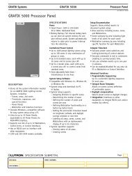
GRAFIK Eye ® Preset Local Lighting ControlsGRAFIK Eye preset local lighting controls allow you toeasily create and recall multiple lighting scenes in aroom. Up to 16 preset scenes can be stored in eachGRAFIK Eye, making them ideal for home cinemas,living rooms, and dining rooms. GRAFIK Eye presetscenes can be easily adjusted at any time. GRAFIK Eyecontrols are available to dim or switch two, three,four, or six zones of lighting.C O N N E C T I O N T O P R O C E S S O RFadeScenesEach <strong>HomeWorks</strong> ® processor has three configurablelinks each capable of controlling up to eight GRAFIKEye control units or WPMs. This connection requirestwo pair [one pair 1.0mm 2 (#18 AWG), one pair 0.5-1.0mm 2(#18-22 AWG) twisted shielded] Class 2/PELVwire. <strong>Lutron</strong> ® wire model GRX-CBL-346S-500 may beused. The maximum cable length is 610m (2,000 feet),and this link must be wired in a daisy-chainconfiguration.A C C E S S O R Y C O N T R O L SHandheld InfraredRemote Control TransmittersGRX-IT, GRX-8IT (white only)Controls four or eight scenes plus masterraise/lower and off.ZonesBuilt-in infrared receiverGRAFIK Eye preset lighting control(GRX-3504-CE shown)G R A F I K E Y E C O N T R O L U N I TI N S TA L L AT I O N N O T E SUse 89mm (3-1/2 inch) deep wallboxes for ease ofinstallation of GRAFIK Eye control units. (<strong>Lutron</strong> model241400)COMPONENTSF I N I S H E S A N D C O L O U R SGRAFIK Eye preset local lighting controls are availablein matt plastic finishes and metallic finishes. Seesection 13.4.8 www.lutron.com
GRAFIK Eye ® Preset Local Lighting ControlsControl UnitsModelInput voltageRegulatory approvalsLoad typesGRX-3502-CE, GRX-3503-CE, GRX-3504-CE, GRX-3506-CE: allows scene and zonecontrol from <strong>HomeWorks</strong> ® .GRX-3102-CE, GRX-3103-CE, GRX-3104-CE, GRX-3106-CE: allows scene control onlyfrom <strong>HomeWorks</strong>.220-240VAC, 50/60HzCE, C-TickIncandescent, magnetic low voltage, electronic low voltage (requires <strong>Lutron</strong> ® lowvoltagetransformers), fluorescent non-dim, neon/cold cathode. The outputs arealso compatible with <strong>Lutron</strong> Power Boosters and interfaces on in section 6Maximum load (CE) See table on page 4.10.Minimum loadEnvironment25W/VA per zone.Ambient temperature: 0-40°C, 32-104°FAmbient humidity: 0-90% humidity, non-condensing. Indoor use only.Cooling methodPassive cooling.Line-voltage connections See figures 3 and 4, page 4.12.Low-voltage wire type Two pair [one pair 1.0mm 2 (#18 AWG), one pair 0.5-1.0mm 2 (#18-22 AWG) twistedshielded] Class 2/PELV wire. <strong>Lutron</strong> wire model GRX-CBL-346S-500 may be used.Low-voltage wiringconfigurationLow-voltage connectionsAddressingMaximum of 610m (2,000 feet) total. Must be wired in a daisy-chainconfiguration. See figures 5 and 6, page 4.13.One 4-pin removable terminal block. Each of the four terminals will accept up totwo 1.0mm 2(#18 AWG) wires. Do not connect terminal 2 on processorcommunication link connector or between GRX units.Via 7-segment display. Use 1 of 8 addresses on a GRAFIK Eye link.COMPONENTSESD protectionMeets or exceeds the IEC 61000-4-2 standard.Surge protectionMeets or exceeds ANSI/IEEE standard c62.41.Air gapProvided when all circuits are off.Power-failure memory Non-volatile RAM.Fail-safe operationIf communication with the processor is interrupted, all GRAFIK Eye controls willstill provide local control.Dimensions See figure 1, page 4.11.Mounting (CE)All CE-compliant units mount in 4-gang US wallbox 7.0cm (2-3/4 inches) deepminimum, 8.9cm (3-1/5 inch) deep recommended for ease of wiring. <strong>Lutron</strong>model 241400 may be used.Shipping weight.9kg (2 pounds)<strong>Technical</strong> Support: hwisupport@lutron.com4.9
GRAFIK Eye ® Preset Local Lighting ControlsGRAFIK Eye control units capacitiesGRAFIK EyemodelVoltageMaximum wattsper zoneMaximum wattsper control unitWallboxsize(gangs)CE non-CE CE non-CE CE non-CE2-zone 220-240V 800 1200 1600 1600 4 23-zone 220-240V 800 1200 2300 2400 4 34-zone 220-240V 800 1200 2300 3000 4 46-zone 220-240V 800 1200 2300 3000 4 4Note: The sum of the wattages of the individual zonescannot exceed the total capacity of the control unit.For wattages exceeding those listed above, a PowerBooster or interface is required.COMPONENTS4.10 www.lutron.com
ZO N E 1 ZO N E 2 ZO N E 3 ZO N E 4ZO N E 5ZO N E 6FADE T E MP O R ARFYZO N E SMAST E R4 9/16"GRAFIK (116mm) Eye ® Preset Local Lighting Controls5/16" 8mm(5/16 inches) (8mm)149mm15/16"(1-15/16 (49mm) inches)A4116mm9/16"(116mm) (4-9/16inches)2-zone 2-ZONE3-ZONE3-zone4-ZONE4-zone 6-ZONE2-ZONE3-ZONE4-ZONECE227mm(8 5/16")227mm(8 5/16")227mm(8 5/16")227mm6-ZONE(8 5/16")Width Width (A)CE NON CECE227mm 141mm227mm(8 5/16") (5 9/16")(8-5/16 inches)227mm 184mm(8 5/16") (7 5/16")227mm227mm 227mm(8 5/16") (8-5/16 5/16") inches)227mm 227mm(8 5/16") 227mm (8 5/16")(8-5/16 inches)WidthNON CE141mm(5 9/16")184mm(7 5/16")227mm(8 5/16")227mm(8 5/16")non-CE141mm(5-9/16 inches)184mm(7-5/16 inches)227mm(8-5/16 inches)ANeed this piece of artworkZO N E 1 ZO N E 2 ZO N E 3 ZO N E 4ZO N E 5ZO N E 6M SNeed this piece of artwork117mm(4 9/16")FADE T E MP O R ARFYM SZO N E SMAST E R117mm(4-9/16117mminches)(4 9/16")6-zone227mm(8-5/16 inches)227mm(8-5/16 inches)Figure 1 – dimensionsCOMPONENTSFigure 2 – mounting<strong>Technical</strong> Support: hwisupport@lutron.com4.11
GRAFIK Eye ® Preset Local Lighting ControlsDistributionpanelEarthLoad 2Load 4Load 6LiveNeutralEarth from distribution panelLoad 2Load 4Load 6USAHOT/LIVE 1 2 34 CLASS 2(2) 2.5mm 2(2) Input power fromIECSSAPEL V2.5mm NEUT RAL2distribution panelNeutral from distribution panelFigure 3 – GRX-3106-AU and GRX-3506-AU wiring diagram (Non-CE)Earth from distribution panelZONE 2 For permanently installedincandescent or ironZONE 1Load 1ZONE 4 core transformer low voltageincandescent fixtures only.ZONE 3Load 3ZONE 6ZONE 5Load 5N(2)PEL1V23 ONL4YNeutral from2.5mm 2 COM 12V MUX XMUGRX-3106-CEdistribution panelSSAZONE 2ZONE 4ZONE 6ZONE 1ZONE 3ZONE 5(2) 2.5mm 2 (2) 2.5mm 2 DistributionCU WIREONLYLoad 1Load 2Load 3Clas s 2panelEarthLiveNeutralZONECAPACITY230V~50/60HzUNI T CAPACITY ::10A,23040-800W0W L(2) 2.5mm 2Input power fromdistribution panelCOMPONENTSFigure 4 – GRX-CE models wiring diagram (-CE)4.12 www.lutron.com
GRAFIK Eye ® Preset Local Lighting ControlsGRAFIK Eye control units can be connectedto any of the three configurable links.ZONE 2ZONE 4ZONE 6CU WIRE ONLYZONE 1ZONE 3ZONE 5HOTSSACLASS 21 2 3 4USA CLASS 2IEC PELVNEUTRALPin 1 - One 1.0mm (#18 AWG) for common2Pin 2 - Do not connectPins 3 and 4 - One pair 1.0-0.5mm (#18-22 AWG)2twisted/shielded for dataWire to otherWPM/GRX control unitsFigure 5 – connection to processorZONE 2ZONE 4ZONE 6HOTSSACU WIRE ONLYCLASS 21 2 3 4USA CLASS 2IEC PELVZONE 1ZONE 3ZONE 5NEUTRALZONE 2ZONE 4ZONE 6HOTSSACU WIRE ONLYCLASS 21 2 3 4USA CLASS 2IEC PELVZONE 1ZONE 3ZONE 5NEUTRALCOMPONENTSFigure 6 – connection to other GRAFIK Eye control unitsNotes:Connection between #2 terminals is not made between GRAFIKEye control units and the <strong>HomeWorks</strong> ® processor.Connection between #2 terminals is not made between twoGRAFIK Eye control units.A maximum of 8 GRX and WPM may be wired to one processorlink.<strong>Technical</strong> Support: hwisupport@lutron.com4.13
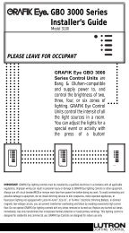
GRAFIK IntegraleTMPreset Local Lighting ControlGRAFIK Integrale has the same features and functionsof the GRAFIK Eye® 3000 series control units. Inaddition, GRAFIK Integrale can directly controlelectronic low-voltage lighting, 0-10V ballasts, DSIballasts and DALI ballasts (intensity broadcast only)without requiring additional interfaces.GRAFIK Integrale is only available in a 4 lighting zoneconfiguration. The total unit capacity is 2300W/VA.The capacity of a single zone is 800W/VA and amaximum of 20 fluorescent ballasts.Connection to processor, accessory controls, andfinishes and colours are the same as GRAFIK Eyemodels. See section 13.ZonesBuilt-in infrared receiverFadeScenesGRAFIK Integrale GXI-3104-T-CE or GXI-3504-T-CElighting controlG R A F I K I N T E G R A L E C O N T R O L U N I TI N S TA L L AT I O N N O T E SUse 89mm (3-1/2 inch) deep wallboxes for ease ofinstallation of GRAFIK Eye control units. (<strong>Lutron</strong>model 241400)COMPONENTS4.14 www.lutron.com
GRAFIK IntegraleTMPreset Local Lighting ControlControl unitModelInput voltageRegulatory approvalsLoad typesGXI-3104-T-CE, GXI-3504-T-CE220-240VAC, 50/60HzCE, C-Tick, VDEIncandescent, magnetic low voltage, neon/cold cathode, fluorescent, electroniclow voltage. Ballast control outputs are compatible with 0-10V, DSI and DALIballasts.Maximum load (CE)Minimum loadEnvironment2300W/VA total, 800W/VA per zone.25W/VA per zone.Ambient temperature: 0-40°C, 32-104°FAmbient humidity: 0-90% humidity, non-condensing. Indoor use only.Cooling methodPassive cooling.Line-voltage connections See figure 1, page 4.16.Low-voltage wire type Two pair [one pair 1.0mm 2 (#18 AWG), one pair 0.5-1.0mm 2 (#18-22 AWG) twistedshielded] Class 2/PELV wire. <strong>Lutron</strong> wire model GRX-CBL-346S-500 may be used.Low-voltage wiringconfigurationLow-voltage connectionsMaximum of 610m (2,000 feet) total. Must be wired in a daisy-chainconfiguration. See figures 5 and 6, page 4.13.One 4-pin removable terminal block. Each of the four terminals will accept up totwo 1.0mm 2(#18 AWG) wires. Do not connect terminal 2 on processorcommunication link connector or between GXI units.COMPONENTSAddressingVia 7-segment display. Use 1 of 8 addresses on a GRAFIK Eye link.ESD protectionMeets or exceeds the IEC 61000-4-2 standard.Surge protectionMeets or exceeds ANSI/IEEE standard c62.41.Air gapProvided when all circuits are off.Power-failure memory Non-volatile RAM.Fail-safe operationIf communication with the processor is interrupted, all GRAFIK Integrale controlswill still provide local control.Dimensions See figure 1, page 4.11.Mounting (CE)All CE-compliant units mount in 4-gang US wallbox 7.0cm (2-3/4 inch) deepminimum, 8.9cm (3-1/5 inch) deep recommended for ease of wiring. <strong>Lutron</strong>model 241400 may be used.Shipping weight.9kg (2 pounds)<strong>Technical</strong> Support: hwisupport@lutron.com4.15
GRAFIK IntegraleTMPreset Local Lighting ControlDistributionpanelEarthLiveNeutralLoad 1Load 2LiveNeutral2.5mm 2 DL/SL 11 2 3 4 - + - + - + - +Load 3DL/SL 2DL/SL 3(2) 2.5mm 2(2)PELV ONLYDL/SL 4}}}}Rear view of GXI-3104 control unit(2) 1.0mm 2+-0-10V and DSIballast wiringLoad 4 -ballast(2) 2.5mm 2Figure 1 – mains voltage wiringL O W - V O LTA G E W I R I N GGRAFIK Integrale uses the same low-voltage wiring asthe GRAFIK Eye® control units. Refer to the diagramson page 4.13.COMPONENTS4.16 www.lutron.com
Wallbox Power Module<strong>HomeWorks</strong> ® Wallbox Power Modules (WPM) control sixzones of lighting. The WPM is designed to be locatedin closets, equipment rooms, and other locations inthe home where it is “hidden” from view. Clients usekeypads to control the lights connected to the WPM.C O N N E C T I O N T O P R O C E S S O RThe WPM is wired like a six-zone GRAFIK Eye ® controlunit (GRX-3506). Each <strong>HomeWorks</strong> processor has threeconfigurable links each capable of controlling up toeight WPM or GRAFIK Eye control units. Thisconnection requires two pair [one pair 1.0mm 2 (#18AWG), one pair 0.5-1.0mm 2(#18-22 AWG) twistedshielded] Class 2/PELV wire. <strong>Lutron</strong> ® wire model GRX-CBL-346S-500 may be used. The maximum cable lengthis 610m (2,000 feet), and this link must be wired in adaisy-chain configuration.The wattage and load type specifications of the WPMare the same as six-zone GRAFIK Eye control unit(GRX-3106/3506 models). All connections on the backof the WPM are identical to those on the six-zoneGRAFIK Eye control unit.D E F A U LT S C E N E B U T T O NEach WPM has a default scene button on the frontthat allows a user to toggle between a preset sceneand OFF. This scene is stored inside the WPM and canbe activated at any time. The default scene provides“fail-safe” operation allowing the WPM to becontrolled locally if communication to the processor islost.W P M B E N E F I T S :Default scenestatus LEDWallbox Power Module• Minimises the number of controls on the wall• Provides a cost-effective dimming solution to jobswith lower wattage loads• Reduces overall job cost by up to 5-20% when lessthan 96 control zones are required• Install in areas where available space is minimal• Compatible with LINCTM prewire boxesDefault scene buttonNote: Use 89mm (3-1/2 inches) deep wallboxes for ease ofinstallation of GRAFIK Eye control units.COMPONENTS<strong>Technical</strong> Support: hwisupport@lutron.com4.17
Wallbox Power ModuleControl UnitsModelInput voltageRegulatory approvalsLoad typesHWI-WPM-6D-230CE: control six zones of lighting. (CE compliant)HWI-WPM-6D-240: control six zones of lighting. (non-CE)220-240VAC, 50/60HzCE, C-Tick (CE compliant model)Incandescent, magnetic low voltage, electronic low voltage (requires <strong>Lutron</strong> ® lowvoltagetransformers), fluorescent non-dim, neon/cold cathode. The outputs arealso compatible with <strong>Lutron</strong> Power Boosters and interfaces in section 6.Maximum load (CE)Maximum load (non CE)Minimum loadEnvironment2200W/VA per control unit, 800W/VA per zone.3000W/VA per control unit, 1200W/VA per zone.25W/VA per zone.Ambient temperature: 0-40°C, 32-104°FAmbient humidity: 0-90% humidity, non-condensing. Indoor use only.Cooling methodPassive cooling.Line-voltage connections See figure 3 and 4, page 4.12.Low-voltage wire type Two pair [one pair 1.0mm 2 (#18 AWG), one pair 0.5-1.0mm 2 (#18-22 AWG) twistedshielded] Class 2/PELV wire. <strong>Lutron</strong> wire model GRX-CBL-346S-500 may be used.COMPONENTSLow-voltage wiringconfigurationLow-voltage connectionMaximum of 610m (2,000 feet) total. Must be wired in a daisy-chainconfiguration. See figure 5, page 4.20.One 4-pin removable terminal block. Each of the four terminals will accept up totwo 1.0mm 2(#18 AWG) wires. Do not connect terminal 2 on processorcommunication link connector or between WPM units.AddressingVia rotary dial. Use 1 of 8 addresses on a GRAFIK Eye ® /WPM link.ESD protectionSurge protectionAir gapPower-failure memoryFail-safe operationMeets or exceeds the IEC 61000-4-2 standard.Meets or exceeds ANSI/IEEE standard c62.41.Provided when all circuits are off.Non-volatile RAM.If communication with the processor is interrupted, all Wallbox Power Moduleswill still allow local control.Dimensions See figures 1 and 2, page 4.19.Mounting4-gang US wallbox, 70mm (2-3/4 inches) deep minimum, 89mm (3-1/2 inches)deep recommended for ease of wiring. If mounting one control above another,leave at least 11.4cm (4-1/2 inches) vertical spacing between them. <strong>Lutron</strong>model 241400 may be used.Shipping weight0.9kg (2 pounds)4.18 www.lutron.com
Wallbox Power Module220mm(8-11/16 inches)126mm(5 inches)Figure 1 – front view8mm (5/16 inches)54mm(2-1/8 inches)126mm(5 inches)Figure 2 – side viewCOMPONENTSWallbox (<strong>Lutron</strong> model 241-400may be used).Wallbox Power ModuleFaceplateFigure 3 – mounting<strong>Technical</strong> Support: hwisupport@lutron.com4.19
Wallbox Power ModuleFigure 4 – rotary address switch location(faceplate removed)Position01-89ABCDEFProper moduleoutput/purposeAll outputs OFFAddress for normal operationOutput 1 full ON, all others OFFOutput 2 full ON, all others OFFOutput 3 full ON, all others OFFOutput 4 full ON, all others OFFOutput 5 full ON, all others OFFOutput 6 full ON, all others OFFAll outputs full ONTable 1 – rotary address dial operationCOMPONENTSZONE 2ZONE 4CU WIRE ONLYZONE 1ZONE 3ZONE 6ZONE 5HOTSSACLASS 21 2 3 4USA CLASS 2IEC PELVNEUTRALPin 1 - One 1.0mm (#18 AWG) for common2Pin 2 - Do not connectPins 3 and 4 - One pair 1.0-0.5mm (#18-22 AWG)2twisted/shielded for dataWire to otherWPM/GRX control unitsFigure 5 – connection to processor4.20 www.lutron.com
Remote PowerModulesandRemote PowerPanelsCOMPONENTS<strong>Technical</strong> Support: hwisupport@lutron.com5.1
Remote Power Modules<strong>HomeWorks</strong> ® Remote Power Modules (RPMs) are used inboth centralised and hybrid system designs to controllighting, motor, and fan loads. There are severaldifferent models of RPMs; each model controls specificload types. The RPMs are mounted in one of theRemote Power Panels.D I M M I N G M O D U L E( M O D E L H W - R P M - 4 U - 2 3 0 - C E )The dimming module has 4 outputs that can dim orswitch incandescent, magnetic low voltage orneon/cold cathode. Each of the four outputs canswitch electronic low-voltage or fluorescent lighting.The total capacity of a dimming module is 13A @230V (3680W/VA) 2 . The maximum capacity of anysingle zone is 10A.D I M M I N G M O D U L E( M O D E L H W - R P M - 4 U - 2 4 0 [ N O N - C E ] )This module has the same characteristics as the abovemodel except this module has a total capacity of 16A@ 220-240VAC. The maximum capacity of any singleoutput is also 16A.M O T O R M O D U L E( M O D E L H W - R P M - 4 M - 2 3 0 )The motor module can control four 3-wire 230V ACmotors for applications such as shades, draperies, andcurtains. Each motor control uses two mechanicallyinterlocked relays for directional control that preventssimultaneous operation of both outputs. Maximumrelay contact rating is 1/2HP, 5A @ 230V for inductiveloads, and 1.5A @ 230V for resistive loads.P O W E R R E L AY M O D U L E( M O D E L H W - R P M - 4 R )The power relay module has 4 outputs that can switchincandescent, neon/cold cathode, magnetic low voltage,electronic low voltage, fluorescent, or high intensitydischarge (HID). The total capacity of a power relaymodule is 64A @ 220-240VAC. The total load capacityof any individual output is limited to 16A @ 220-240VAC, 1/3 HP.A D A P T I V E D I M M I N G M O D U L E( M O D E L M O D E L H W - R P M - 4 A - 2 3 0 )COMPONENTSThe adaptive dimming module has 4 outputs that candim incandescent, magnetic low-voltage, electroniclow-voltage or neon/cold cathode. The adaptivemodule uses our RTISS-TE technology to supply stablepower to the lights even in harsh power lineconditions. The total load capacity of the module is13A @ 230V (2990W). The total load capacity of anyindividual output is 8A (1840V).The adaptive dimming module is ideal for applicationswhere power conditions are non-ideal such as yachtsand ships. The adaptive dimming module may be usedwith any combination of other Remote Power Moduleswithin a <strong>HomeWorks</strong> Remote Power Panel.C O N N E C T I O N T O M O D U L E I N T E R F A C EAll RPMs must be connected to a Module Interfacelocated within the same Remote Power Panel. If aprocessor is located in the same panel as RPMs, aprocessor with an integral Module Interface must beused (either model H8P5-MI-CE and H8P5-MI-H48-CE).RPMs within an enclosure are connected to the ModuleInterface using a wire harness provided by <strong>Lutron</strong>.5.2 www.lutron.com
Remote Power ModulesHW-RPM-4U-230-CE, HW-RPM-4U-240 • dimming moduleLoad typesIncandescent, magnetic low voltage, electronic low voltage (requires <strong>Lutron</strong>® lowvoltagetransformers) neon/cold cathode, fluorescent non-dim. The outputs arecompatible with <strong>Lutron</strong> Power Boosters and interfaces in section 6.Maximum loadCE model: 13A total, 8A maximum per output.Non-CE model: 16A total, 16A maximum per output.Wiring Terminal blocks in the power panel will accept one 1.0-2.5mm 1 (#18-10 AWG)wire or two 1.0-1.5mm 1 (#18-16 AWG) wires. See figure 1, page 5.6.TechnologyForward phase control using triac technology.Equipped with RTISS, Real Time Illumination Stability System.InterferencesuppressionAir gapEMI/RFI suppression circuitry.Provided when all four circuits are off.HW-RPM-4A-230 • adaptive dimming moduleLoad typesIncandescent, magnetic low voltage, electronic low voltage, and neon/coldcathode. The outputs are compatible with <strong>Lutron</strong> Power Boosters and interfaces.Maximum load13A total, 8A maximum per per output.Wiring Terminal blocks in the power panel will accept one 1.0-2.5mm 1 (#18-10 AWG)wire or two 1.0-1.5mm 1(#18-16 AWG) wires.COMPONENTSTechnologyInterference suppressionAir gapForward and reverse phase control using FET technology.Equipped with RTISS-TE, Real Time Illumination Stability System enhanced forTrailing Edge dimming.Contains limited short-circuit and overload protection.EMI/RFI suppression circuitry.Provided when all four circuits are off.<strong>Technical</strong> Support: hwisupport@lutron.com5.3
Remote Power ModulesHW-RPM-4M-230 • motor moduleLoad typesBi-directional three-wire 120V motor loads, or incandescent non-dim. Outputs arenot rated for switching electronic low-voltage or electronic ballasts.Maximum load1/2 HP per circuit. 5A maximum per circuit for motor loads, 1.5A maximum percircuit for tungsten loads.Wiring Terminal blocks will accept one 1.0-2.5mm 1 (#18-10 AWG) wire or two 1.0-1.5mm 1(#18-16 AWG) wires. Requires that four additional terminal blocks be mountedonto the DIN rail assembly. See figure 2, page 5.6.TechnologyInterferencesuppressionAir gapRelay switching, mechanical-interlocked relays guarantee motor protection.EMI/RFI suppression circuitry.Provided when all four circuits are off.HW-RPM-4R • power relay module (120V-240V)Load typesNon-dim loads.Maximum load64A total, 16A, 1/3 hp maximum per output.COMPONENTSWiring Terminal blocks will accept one 1.0-2.5mm 1 (#18-10 AWG) wire or two 1.0-1.5mm 1(#18-16 AWG) wires. Requires the installation of four additional gray terminalblocks and three additional black terminal blocks to be mounted on to the DINrail assembly. Gray terminal blocks accept one 0.75-10mm 1(#18-8 AWG) wire ortwo 1.5-4.0mm 1 (#16-12 AWG) wires. See figure 3, page 5.6.TechnologyPatented SoftswitchTM triac arc suppression technology used to extend relay life.Interference suppressionAir gapEMI/RFI suppression circuitry.Provided when all four circuits are off.5.4 www.lutron.com
Remote Power ModulesAll Remote Power ModulesModelHW-RPM-4U-230-CE: dimming module CE compliant.HW-RPM-4U-240: dimming module (non-CE).HW-RPM-4M-230: motor module.HW-RPM-4R: power relay module.HW-RPM-4A-230: adaptive dimming module.Input voltageRPM-4U, RPM-4M, RPM-4A: 220-240VAC, 50/60HzRPM-4R: 108-264VAC, 50/60HzNumber of outputs 4Regulatory approvals CE, C-TICK (except HW-RPM-4U-240)EnvironmentAmbient temperature: 0-40°C, 32-104°FAmbient humidity: 0-90% humidity, non-condensing. Indoor use only.Cooling methodHeat generatedfully loadedLine-voltage connectionsPassive cooling.Dimming modules will generate up to 75 BTUs per hour when fully loaded.Separate line-voltage feeds at the DIN rail terminal blocks for each RPM. Terminalblocks should be tightened to .40-.57nM (3.5-5.0 inches-pounds).Low-voltagecommunicationsAddressingDiagnosticsESD protectionSurge protectionFail-safe operationCommunication harness provided by <strong>Lutron</strong>.Rotary switch. Counts as 1 of 8 RPM addresses per MI.LED provided to indicate proper communications with Module Interface.Meets or exceeds the IEC 61000-4-2 standard.Meets or exceeds ANSI/IEEE standard c62.41.Rotary switch on the RPM allows for manual operation of each load.COMPONENTSDimensionsMountingShipping weightMinimum load99mm (3-7/8 inches) wide x 178mm (7 inches) highHWI-PNL-8 and the HWBP-8D Remote Power Panels will hold up to 8 RPMs.HWI-PNL-5 Remote Power Panel will hold up to 5 RPMs.Note: RPMs may hum slightly and internal relays will click when in use. Mount where suchnoise is acceptable. Locate at least 1.8m (6 feet) away from sensitive electronicequipment.1.0kg (2.2 pounds)25W/VA per output.<strong>Technical</strong> Support: hwisupport@lutron.com5.5
Remote Power Modules – Wiring Diagrams220-240 VAC liveNeutralFromdistributionpanelDimmed hot 1Dimmed hot 2Dimmed hot 3Dimmed hot 4Load neutral 1Load neutral 2Load neutral 3Load neutral 4Removable bypassjumpersDLDL 1DL 2DL 34LNRed 1Red 2Red 3Red 4BrownBlueFigure 1 – HW-RPM-4U-230-CE, HW-RPM-4U-240, HW-RPM-4E-230-CE, and HW-RPM-4A-230ABDimensionsmm99178inches3-7/87Rotary address switch4-pin connector forModule Interfaceassembly harness220-240 VAC live from distribution panel(20A)Neutral from distribution panelRaiseLowerRaiseLowerRed 1Yellow 1Red 2Yellow 2Red 3Yellow 3Red 4Yellow 4BrownCOMPONENTSBlueRotary address switch4-pin connector forModule Interfaceassembly harnessFigure 2 – HW-RPM-4M-230120-240V livefrom distributionpanelNeutral fromdistributionpanelSH 1H1N1N2 H2SH 2SH 3H3N3SH 4H4N4Red 1Black 1Control neutralRed 2Black 2Red 3Black 3Red 4Black 4Control powerRotary address switch4-pin connector forModule Interfaceassembly harnessFigure 3 – HW-RPM-4R5.6 www.lutron.com
Remote Power Modules –Rotary Address SwitchEnlarged view ofrotary address switchR O TA R Y A D D R E S S S W I T C H P O S I T I O NF O R H W - R P M - 4 U , 4 E , 4 R , 4 AR O TA R Y A D D R E S S S W I T C H P O S I T I O NF O R H W - R P M - 4 MPositionModule output/purposePositionModule output/purpose0All outputs OFF0All relays OFF1-8Address fornormal operation1-8Address fornormal operation9, ANot used9, A-DNot usedBCOutput 1 ONuse for temporary lightingand/or zone testingOutput 2 ONuse for temporary lightingand/or zone testingEFAll raise relays ONuse for directionalmotor testingAll lower relays ONuse for directionalmotor testingCOMPONENTSDOutput 3 ONuse for temporary lightingand/or zone testingEOutput 4 ONuse for temporary lightingand/or zone testingFAll outputs ONuse for temporary lightingand/or zone testing<strong>Technical</strong> Support: hwisupport@lutron.com5.7
Module InterfaceModule Interfaces control up to eight RPMs and areavailable in two configurations: either integral to a<strong>HomeWorks</strong> ® processor or as a stand-alone component.Each <strong>HomeWorks</strong> 8 series processor can control up to16 Module Interfaces.S TA N D - A L O N E M O D U L E I N T E R F A C E( M O D E L H W I - M I - 2 3 0 )A stand-alone Module Interface controls up to eightRPMs in a Remote Power Panel that does not contain aprocessor. A stand-alone Module Interface installs inHWI-PNL-8-CE, HWI-PNL-5-CE, PBK8-40-13-CE or PBK8-40-13-10-CE.I N T E G R A L M O D U L E I N T E R F A C ESome 8 series processor models (model HWI-PM-230,HWI-PM-H48-230, H8P5-MI-CE and H8P5-MI-H48-CE)contain integral Module Interfaces, allowing up toeight RPMs to be installed in the same panel. Theprocessors with integral Module Interfaces must beinstalled in a HWI-PNL-8-CE Remote Power Panel.View ofstand-alone Module Interface(HWI-MI-230)M A N U A L O V E R R I D E C A PA B I L I T I E SCOMPONENTSA manual override input is provided on each ModuleInterface, allowing a preset lighting scene to beactivated from switches installed anywhere in thehome.C O N N E C T I O N T O P R O C E S S O REach <strong>HomeWorks</strong> 8 series processor has onecommunication link (Link 1) dedicated to the controlof up to 16 MIs. This connection must be daisychainedand requires two pair [one pair 1.0mm 2 (#18AWG), one pair 1.0-0.5mm 2(#18-22 AWG) twistedshielded] Class 2/PELV wire. <strong>Lutron</strong> wire model GRX-CBL-346S-500 may be used.Processor with a module interface included5.8 www.lutron.com
Module InterfaceSpecifications apply to HWI-MI-230 stand-alone Module Interfaces and to Module Interfacesintegral to <strong>HomeWorks</strong> ® 8 series processorsModelHWI-MI-230: stand-alone Module Interface.HWI-PM-230, HWI-PM-H48-230, H8P5-MI-CE, H8P5-MI-H48-CE:8 series processor with integral Module Interface.Input voltageWhen integral to a processor, the MI is powered by 15VDC provided by terminals1 and 2 on the processor communications link connector. When a stand-alone MIis used, it is powered by a separate line-voltage feed (220-240VAC, 50/60Hz) atthe DIN rail terminal blocks and should not have terminal 2 connected on theprocessor communications link connector.Regulatory approvalsEnvironmentCE, C-TICKAmbient temperature: 0-40°C, 32-104°FAmbient humidity: 0-90% humidity, non-condensing. Indoor use only.Cooling methodPassive cooling.Low-voltage wire type Two pair [one pair 1.0mm 2 (#18 AWG), one pair 1.0-0.5mm 2 (#18-22 AWG) twistedshielded] Class 2/PELV wire. <strong>Lutron</strong>® wire model GRX-CBL-346S-500 may be used.Low-voltage wiringconfigurationLow-voltage connectionAddressingMaximum wire length of 305m (1,000 feet). Must be wired in a daisy-chainconfiguration. Link Terminator (LT-1) is required if total cable length exceeds15m (50 feet).One 4-pin removable terminal block. Each of the four terminals will accept up totwo 1.0mm 2(#18 AWG) wires.Rotary switch. Counts as 1 of 16 MI addresses on an MI link.COMPONENTSDiagnosticsThree LEDs for troubleshooting communications with the processor and the RPMs.ESD protectionSurge protectionMiswire ProtectionFail-safe operationMeets or exceeds the IEC 61000-4-2 standard.Meets or exceeds ANSI/IEEE standard c62.41.All terminal block inputs are over-voltage and miswire protected against wirereversals and shorts.The manual override scene is activated for all RPMs connected to the MI byclosing a switch that is wired between the two manual override terminals. Theswitch (or relay) contacts must be rated for switching 50 milliamps at 30VDC. Asingle switch can be used for multiple MIs wired in parallel, but proper polaritymust be maintained across all units. In this configuration, the switch must berated for the sum of the current for all of the MIs connected (e.g., six MIs wiredto a single manual override switch requires a switch rated for 300 milliamps at30VDC).<strong>Technical</strong> Support: hwisupport@lutron.com5.9
Module InterfaceSpecifications apply to HWI-MI-230 stand-alone Module Interfaces and to Module Interfacesintegral to <strong>HomeWorks</strong> ® 8 series processorsMounting dimensions See figure 1, page 5.11.MountingSee figures 2, 3 and 4 on page 5.11. An integral MI is mounted within theprocessor. A stand-alone MI mounts in the lower right-hand corner of a panelenclosure (HWI-PNL-8-CE, HWI-PNL-5_CE, PBK8-40-13-CE and PBK8-40-13-10-CE).Shipping weightOutput1.8kg (4 pounds)Compatible with HW-RPM-4U dimming module, HW-RPM-4E ELV module, HW-RPM-4M motor module, HW-RPM-4R power relay module, and HW-RPM-4A adaptivedimming module.COMPONENTS5.10 www.lutron.com
Module Interface75mm (3 inches)91mm (3-5/8 inches)333mm(13-1/8 inches)Figure 1 – HWI-MI-230 dimensionsProcessor with a module interface includedCOMPONENTSFigure 3 – HWI-MI-230 mounted in anPBK-40-13-CE enclosureFigure 4 - HWI-MI-230 mounted in anHWI-PNL-5-CE enclosure<strong>Technical</strong> Support: hwisupport@lutron.com5.11
Remote Power Panels (without breakers)Remote Power Panels are available in two differentsizes. The number of Remote Power Panels and thetypes of components within them may be specified tofit the size, lighting plan, and design of a home.Remote Power Panels may contain <strong>HomeWorks</strong> ® 8 seriesprocessors, Remote Power Modules, or ModuleInterfaces. Shown below are a few of the possibleconfigurations.F I V E - M O D U L E R E M O T E P O W E R PA N E L( M O D E L H W I - P N L - 5 - C E )Accommodates the following combination ofcomponents:Remote Power ModulesE I G H T - M O D U L ER E M O T E P O W E R PA N E L( M O D E L H W I - P N L - 8 - C E )Module InterfaceAccommodates one of the followingcombinations of components:RemotePowerModulesRemote PowerModules• Module Interface (1)• Remote Power Modules (5 maximum)Note: HWI-PNL-5 cannot include a <strong>HomeWorks</strong> processorCOMPONENTS8 seriesprocessorModuleInterface• Processor (1)• Remote Power Modules(8 maximum)• Module Interface (1)• Remote Power Modules(8 maximum)5.12 www.lutron.com
Remote Power Panels (without breakers)ModelCapacityHWI-PNL-8-CE: eight module Remote Power Panel.Eight RPMs (HW-RPM-4U, HW-RPM-4E, HW-RPM-4M, HW-RPM-4R, andHW-RPM-4A) and one Module Interface or 8 series processor.Regulatory approvalsEnvironmentCE, C-TICKAmbient temperature: 0-40°C, 32-104°FAmbient humidity: 0-90% humidity, non-condensing. Indoor use only.Cooling methodPassive cooling.Mount in a place where the vented cover will not be blocked.Heat generatedfully loaded600 BTUs per hour maximum.Line-voltageconnectionsUse copper wire only, supply conductors 60/75°C. DIN rail-mounted terminalblocks provided for line-voltage Remote Power Module (RPM) wiring andprocessor/MI power. Terminal blocks should be tightened to .40-.57nM (3.5-5.0inches-pounds). See page 5.6.DIN rail terminal blocks Terminal blocks will accept one 1.0-2.5mm 2 (#18-10 AWG) wire or two 1.0-1.5mm 2(#18-16 AWG) wires. Terminal blocks should be tightened to .40-.57 nM (3.5-5.0inches-pounds). All terminal blocks are shipped with bypass jumpers installed.After verifying that each circuit is wired correctly, remove the bypass jumpers forsystem operation.Ground bar terminalsMiswire protection24 ground termination points.All terminal blocks are shipped with bypass jumpers installed.COMPONENTSMounting Panel must be mounted within 7 degrees from vertical. Allow at least 30cm (12inches) air space at top and bottom and a minimum of 30cm (12 inches)clearance in front of panel. Remote Power Panels will hum slightly and internalrelays will click while in use. Locate where such noise is acceptable. Locate thepanel so that line-voltage wiring will be at least 1.8m (6 feet) from audio orelectronic equipment and its wiring.DimensionsConstructionShipping weight36.5cm (14-3/8 inches) x 150cm (59 inches) x 9.8cm (3-7/8 inches)Enclosure: 16-gauge galvanized sheet metal (unpainted).Cover: Painted (black) metal cover with ventilation holes.11.4kg (25 pounds)<strong>Technical</strong> Support: hwisupport@lutron.com5.13
Remote Power Panels (without breakers)ModelCapacityRegulatory approvalsEnvironmentHWI-PNL-5-CE: five module Remote Power Panel.Five RPMs (HW-RPM-4U, HW-RPM-4E, HW-RPM-4M, HW-RPM-4R, andHW-RPM-4A) and one Module Interface.CE, C-TICKAmbient temperature: 0-40°C, 32-104°FAmbient humidity: 0-90% humidity, non-condensing. Indoor use only.Cooling methodPassive cooling.Mount in a place where the vented cover will not be blocked.Heat generatedfully loaded420 BTUs per hour maximum.Line-voltageconnectionsUse copper wire only, supply conductors 60/75°C. DIN rail-mounted terminalblocks provided for line-voltage Remote Power Module (RPM) wiring andprocessor/MI power. Terminal blocks should be tightened to .40-.57nM (3.5-5.0inches-pounds). See page 5.6.DIN rail terminal blocks Terminal blocks will accept one 1.0-2.5mm 2 (#18-10 AWG) wire or two 1.0-1.5mm 2(#18-16 AWG) wires. Terminal blocks should be tightened to .40-.57 nM (3.5-5.0inches-pounds). All terminal blocks are shipped with bypass jumpers installed.After verifying that each circuit is wired correctly, remove the bypass jumpers forsystem operation.COMPONENTSGround bar terminalsMiswire protection24 ground termination points.All terminal blocks are shipped with bypass jumpers installed.Mounting Panel must be mounted within 7 degrees from vertical. Allow at least 30cm (12inches) air space at top and bottom and a minimum of 30cm (12 inches)clearance in front of panel. Remote Power Panels will hum slightly and internalrelays will click while in use. Locate where such noise is acceptable. Locate thepanel so that line-voltage wiring will be at least 1.8m (6 feet) from audio orelectronic equipment and its wiring.DimensionsConstructionShipping weight36.5cm (14-3/8 inches) x 81cm (32 inches) x 9.8cm (3-7/8 inches)Enclosure: 16-gauge galvanized sheet metal (unpainted).Cover: Painted (black) metal cover with ventilation holes.8.6kg (18 pounds)5.14 www.lutron.com
Remote Power Panels (without breakers)Installation1cm(3/8 inches)6cm(2-1/2inches)20cm(8 inches)1cm(3/8 inches)Preferred powerwiring entry8mm diameter(5/16 inches)106cm(41-3/4 inches)150cm(59inches)16mm diameter(5/8 inch)keyholes forsurfacemounting (4places)Module locations(8 maximum)Terminal blocksUp-7º +7º37cm(14-3/4 inches)22cm(11 inches)Mount panelverticallyScrewsfor recessmounting(4 places)38.5cm(15-1/8 inches)36.5cm(14-3/8inches)Alternate powerwiring entryControl wiring entry(Class 2/PELV)Figure 1 – HW-PNL-8-CE panel dimensionsPanel is 9.8cm (3-7/8 inches) deep.Figure 2 – wiring entry36.5cm(14-3/8 inches)18cm(7 inches)8mm diameter(5/16 inches)Preferred powerwiring entryCOMPONENTS81cm(32")74cm(29inches)16mm diameter(5/8 inch)keyholes forsurfacemounting (4places)Up-7º +7ºScrewsfor recessmounting(4 places)38.54cm(15-1/8 inches)Mount panelvertically19cm(7-1/2 inches)Alternate powerwiring entryControl wiringentry (Class2/PELV)Figure 1 – HW-PNL-5-CE panel dimensionsPanel is 9.8cm (3-7/8 inches) deep.Figure 2 – wiring entry<strong>Technical</strong> Support: hwisupport@lutron.com5.15
Remote Power Panels (with breakers)Remote Power Panels with breakers include inputbreakers and optional 10A output breakers. RemotePower Panels with breakers require only one 3-phasefeed from the main distribution panel, reducing thenumber of wiring connections required.Terminal blocksBreakersMain lugsModule InterfaceRemote Power Panel with input breakers(PBK8-40-13-CE)COMPONENTSTerminal blocksModule InterfaceRemote Power Panel with input and output breakers(PBK8-40-13-10-CE)5.16 www.lutron.com
Remote Power Panels (with breakers)ModelCapacityRegulatory approvalsEnvironmentPBK8-40-13-CE, PBK8-40-13-10-CEEight RPMs (HW-RPM-4U and HW-RPM-4A) and one Module Interface or 8 seriesprocessor.CE, C-TICKAmbient temperature: 0-40°C, 32-104°FAmbient humidity: 0-90% humidity, non-condensing. Indoor use only.Cooling methodPassive cooling.Mount in a place where the vented cover will not be blocked.Heat generatedfully loaded600 BTUs per hour maximum.Line-voltageconnectionsUse copper wire only, supply conductors 60/75°C. DIN rail-mounted terminalblocks provided for line-voltage Remote Power Module (RPM) wiring andprocessor/MI power. Terminal blocks should be tightened to .40-.57nM (3.5-5.0inches-pounds).DIN rail terminal blocks Terminal blocks will accept one 1.0-2.5mm 2 (#18-10 AWG) wire or two 1.0-1.5mm 2(#18-16 AWG) wires. Terminal blocks should be tightened to .40-.57 nM (3.5-5.0inches-pounds). All terminal blocks are shipped with bypass jumpers installed.After verifying that each circuit is wired correctly, remove the bypass jumpers forsystem operation.Ground bar terminalsMiswire protectionMounting40 ground termination points.All terminal blocks are shipped with bypass jumpers installed.Panel must be mounted vertically (+/- 7 degrees from vertical). Allow at least30cm (12 inches) air space at top and bottom and a minimum of 30cm (12inches) clearance in front of panel. Remote Power Panels will hum slightly andinternal relays will click while in use. Locate where such noise is acceptable.Locate the panel so that line-voltage wiring will be at least 1.8m (6 feet) fromaudio or electronic equipment and its wiring.COMPONENTSDimensionsConstructionShipping weight42.7cm (16-7/8 inches) x 160cm (63 inches) x 10.2cm (4 inches)Enclosure: 16-gauge galvanized sheet metal (unpainted).Cover: painted (black) metal cover with ventilation holes.30.9kg (68 pounds)<strong>Technical</strong> Support: hwisupport@lutron.com5.17
Remote Power Panels (with breakers)Installation33cm(13 inches)5.4cm(2-1/8 inches)8mm diameter(5/16 inch)111.8cm(44-1/2 inches)16mm diameter(5/8 inch)keyholes forsurface mounting(4 places)160cm (63 inches)41.6cm(16-3/8 inches)33cm(13 inches)Up-7º +7ºMount panelverticallyMI mountingscrew locationsCOMPONENTSScrewsfor recessmounting(4 places)45.7cm(18 inches)Figure 21 – panel dimensionsPanel is 10.2cm (4 inches) deep.42.7cm (16-7/8 inches)Load wiring entryNotes:1. PBK8-40-13-CE has one 3-phase, 4-pole, 40 Amp main inputbreaker; eight (8) 13 Amp branch circuit input breakers; andone (1) 13 Amp input control breaker.2. PBK8-40-13-10-CE also has thirty two (32) 10 Amp outputbreakers.Terminal blocksMain feed entryGround lugControl wiring entry(Class 2/PELV)Figure 22 – wiring entry5.18 www.lutron.com
Power BoostersandInterfacesCOMPONENTS<strong>Technical</strong> Support: hwisupport@lutron.com6.1
Power Boosters and InterfacesPower Boosters and interfaces are required in someapplications to increase the load capacity of acomponent or to interface with a specific type of load.Power Boosters and interfaces can be used with<strong>HomeWorks</strong> Maestro switches, GRAFIK Eye® controlunits, GRAFIK IntegraleTM control units, Wallbox PowerModules and Remote Power Modules. Power Boostersand interfaces are typically installed in electricalclosets or other hidden locations.F L U O R E S C E N T D I M M I N GB A L L A S T I N T E R F A C E M O D E LN G R X - F D B I - A U ( N O N - C E )Fluorescent Dimming BallastInterfaces are used to dim a singlezone of fluorescent lighting with<strong>Lutron</strong> Hi-lume® dimming ballasts.P O W E R B O O S T E R M O D E L SN G R X - P B - C E A N DN G R X - P B - A U ( N O N - C E )Power Boosters increase the capacityof a single zone of lighting.Compatible load types areincandescent, magnetic low voltage,electronic low voltage (requires<strong>Lutron</strong> low-voltage transformers), andneon/cold cathode.0 – 1 0 V I N T E R F A C EM O D E L G R X - T V I0-10V interfaces are used to dim asingle zone of fluorescent lightingwith dimming ballasts that require a0-10V signal for control. The TVI canalso be used to switch 10 Amps ofnon-dim electronic ballasts or 1/2HP motors.COMPONENTSE L E C T R O N I C L O W - V O LTA G EI N T E R F A C E M O D E L SN G R X - E L V I - C E A N DN G R X - E L V I - A U ( N O N - C E )Electronic Low-Voltage Interfaces areused to dim a single zone ofelectronic low-voltage lighting. TheELVI is not necessary for use withGRAFIK Integrale or if <strong>Lutron</strong> lowvoltagetransformers are used (seepage 10.7 of the TRG Rev. E).T E N V O LT M O D U L E SM O D E L T V MTVM modules can be located in<strong>HomeWorks</strong>® Remote Power Panels.The TVM module is used incombination with the HW-RPM-4Umodule to control fluorescent dimmingballasts that use either a 0-10Vcontrol signal, the DSI control signal,a PWM control signal or the DALIcontrol signal (intensity broadcastonly). For more information consult<strong>Lutron</strong> technical support.S Y N T H E T I C M I N I M U ML O A D I N T E R F A C EL U T - L B X - C E - W HProvides the required minimum loadto a dimmer when the actual load isless than the minimum.D M X - 5 1 2 I N T E R F A C EL U T - D M XLUT-DMX connects to the MI Link(1) of an 8-series processor. Theinterface converts zone dimminglevelsto DMX-512 protocol. Formore information consult <strong>Lutron</strong>technical support.6.2 www.lutron.com
Power Boosters and InterfacesModelNGRX-PB-AU, NGRX-PB-CE: Power Booster.NGRX-ELVI-AU, NGRX-ELVI-CE: Electronic Low-voltage Interface.NGRX-FDBI-AU: Fluorescent Dimming Ballast Interface.Input voltageRegulatory approvalsLoad types220-240VAC, 50/60HzCE, C-Tick (CE models)NGRX-PB-: incandescent, magnetic low voltage, neon/cold-cathode, electronic lowvoltage (requires <strong>Lutron</strong> low-voltage transformer).NGRX-ELVI-: electronic low voltageNGRX-GRX-FDBI-: <strong>Lutron</strong> Hi-lume ® fluorescent dimming ballasts.Maximum loadMinimum loadEnvironmentNGRX-PB-AU: 10 ampsNGRX-PB-CE: 8 amps surface mounted, 5.2 amps flush mountedNGRX-ELVI-: 5 amps (CE and non-CE models)NGRX-FDBI-AU: 10 amps25W/VAAmbient temperature: 0-40°C, 32-104°FAmbient humidity: 0-90% humidity, non-condensing. Indoor use only.Cooling methodHeat generatedfully loadedLine-voltageconnectionsESD protectionSurge protectionMountingPassive cooling.200 BTUs per hour.See figures 2-6, pages 6.4-6.6Meets or exceeds the IEC 61000-4-2 standard.Meets or exceeds ANSI/IEEE standard c62.41.2-gang US wallbox, 70mm (2-3/4 inches) deep minimum, 89mm (3-1/2 inches)deep recommended. (2) <strong>Lutron</strong> P/N 241218 may be used.COMPONENTSTerminals Each terminal will accept two 2.5mm 2 (#12 AWG) wires.Shipping weight.5kg (1 pound)116mm(4-5/8 inches)114mm(4-1/2 inches)Figure 1 – dimensions17mm (11/16 inch)48mm(1-15/16inches)<strong>Technical</strong> Support: hwisupport@lutron.com6.3
Power Boosters – Wiring DiagramsRemote switch 1 Switch 2NGRX-PB-AU or NGRX-ELVI-AULightingloadLUTRON2 2PELVLUTRONZone out ~➚Live ~EarthDO NOT USEZone inNeutral NL 11L 1 1NLive220-240VAC50/60HzNeutralFigure 2 – NGRX-PB-AU and NGRX-ELVI-AU with <strong>HomeWorks</strong> ® Maestro ®Remote switch 1 Switch 2NGRX-PB-CE or NGRX-ELVI-CELightingloadLUTRON2 2PELVLUTRONDO NOT USELive ~EarthZone Out ~➚Zone InNeutral NCOMPONENTSLive220-240VAC50/60HzL 11L 1 1NNeutralFigure 3 – NGRX-PB-CE and NGRX-ELVI-CE with <strong>HomeWorks</strong> Maestro12Up to nine <strong>HomeWorks</strong> Maestro remote switches may be connected to a <strong>HomeWorks</strong> Maestro switch. Total wire length betweenall devices cannot exceed 50m (165 feet).Switches must be connected on the interface side of a multi-location installation.6.4 www.lutron.com
Power Boosters – Wiring DiagramsNGRX-PB-AU or NGRX-ELVI-AUHW-RPM-4U-240Lighting load220-240VACNeutral220-240VACNeutralFigure 4 – NGRX-PB-AU or NGRX-ELVI-AU with Remote Power ModulesNGRX-PB-CE or NGRX-ELVI-CEHW-RPM-4U-240Lighting loadDO NOT USELive ~EarthZone out ~➚Zone inNeutral NCOMPONENTSZone out ~➚Live ~EarthDO NOT USEZone inNeutral N220-240VACNeutral220-240VACNeutralFigure 5 – NGRX-PB-CE or NGRX-ELVI-CE with Remote Power Modules<strong>Technical</strong> Support: hwisupport@lutron.com6.5
FDBI – Wiring Diagrams<strong>Lutron</strong> ® Hi-lume ® fluorescentdimming ballast(s)NGRX-FDBI-AUHW-RPM-4U-240Zone out ~➚Live ~EarthSW LiveZone inNeutral N220-240VACNeutral220-240VACNeutralFigure 6 – NGRX-FDBI-AU installation with Remote Power ModulesRemote switch 1 Switch 2LUT-LBXLightingloadCOMPONENTSLiveL 1 1LUTR ON2 2PEL VL 11 NLUTR ONLive ~Neutral NEarth220-240VAC50/60HzNeutralFigure 7 – LUT-LBX6.6 www.lutron.com
®.0-10V InterfaceModelInput voltageRegulatory approvalsLoad typesMaximum loadMinimum loadEnvironmentGRX-TVI100-277VAC, 50/60HzCE, C-Tick, UL, CSA, NOMFluorescent dimming ballast which accept 0-10V control signal.10 amps or 1/2 HP25W/VAAmbient temperature: 0-40°C, 32-104°FAmbient humidity: 0-90% humidity, non-condensing. Indoor use only.Cooling methodPassive cooling.0-10V output rating 10uA-300mA, sinks current only.Line-voltageconnectionsESD protectionSurge protectionMountingSee figure 2, page 6.8.Meets or exceeds the IEC 61000-4-2 standard.Meets or exceeds ANSI/IEEE standard c62.41.Wall mounted.Terminals Each terminal will accept two 2.5mm 2 (#12 AWG) wires.Shipping weight2kg (4.5 pounds)COMPONENTSCOOPERSBURGG 2 CB, PA 18036 U.S.A144-317 Rev. 1.9GRX-TVI0-10V INTE RFACE ONTROL CControl put: In100-120V, 220- 240V 0/60Hz 5SwitchedOutput: 100-277Ratings ®DLoad Type Swit chedIncandescentFluorescentMagneti c Low-voltag eElectronic Low-volta geNeon/ColdCa thodeMot orRatingsLoad Type Swit chedSwitched µ16A5A16A16A16A1/41/2HP@120HP@27VV✔ ACN 003 715 27710A5AX10A10A10AGRX-TVIConnputtrolI RatingIH2 0.02AIDH2 0.1A0-10V Output RatingMa x. 0.3A Clas s 2GRX-TVIConnputtrolI RatingIH2 0.02AIDH2 0.1A0-10V Output RatingMa x. 0.3A PE LVBwallCAEABCDEDimensionsmm15531810229884inches6.1012.504.011.753.30Figure 1 - dimensions<strong>Technical</strong> Support: hwisupport@lutron.com6.7
0-10V Interface – Wiring Diagrams220-240VAC liveNeutralDLDL 1DL 2DL 34LNRed 1Red 2Red 3Red 4BrownBlueL2/H2220-240VDL2/D H2N2L1/H1N1 N1SL1/SH10-10 Volt240V220-127V100- N2DL2/DH2 L1/H1 N1 N1 SL1/S H1 + –L2/H2 0-10VControl nputs I 277V100-LoadSw itched Max0.3A0-10V control signal wires –DO NOT CONNECT TO MAINS0-10 volt ballastEarth0-10 volt ballastEarthEarthFigure 2 - GRX-TVI with a Remote Power ModuleCOMPONENTS6.8 www.lutron.com
KeypadsandContact ClosureInterfacesCOMPONENTS<strong>Technical</strong> Support: hwisupport@lutron.com7.1
Keypads<strong>HomeWorks</strong> ® keypads are available in many styles,colours, and finishes. Keypads provide clients witha simple and elegant way to operate lights, shades,motorised screens, and many other devices. Keypadshave LEDs that provide status indication. <strong>Lutron</strong>provides custom engraving to clearly identify eachbutton’s function.Each button on every keypad model can beprogrammed to control any lighting load ordevice on the <strong>HomeWorks</strong> system.Each <strong>HomeWorks</strong> processor has three or fourconfigurable links, each capable of controllingup to 32 keypads and Contact Closure Interfaces.C O N N E C T I O N T O P R O C E S S O RUp to 32 keypads can be connected to a single link ona <strong>HomeWorks</strong> processor using two pair [one pair 1.0mm 2(#18 AWG), one pair 1.0-0.5mm 2 (#18-22 AWG) twistedshielded] Class 2/PELV cable. Keypads may be wired ina daisy-chain, home run, star, or T-tap configuration.The maximum total cable length of any wire run is305m (1,000 feet) with up to 10 keypads orinterfaces. The maximum total cable length is 1220m(4,000 feet).COMPONENTS7.2 www.lutron.com
Keypad StylesEuropean-style2-buttonseeTouchTM - without insertSignature SeriesTMseeTouch - with insertArchitraveTMSlim buttonWebLarge buttonCOMPONENTSTabletop(see chapter 10)Slim button - with insert<strong>Technical</strong> Support: hwisupport@lutron.com7.3
European-style KeypadsE U R O P E A N - S T Y L E K E Y PA D SEuropean-style keypads provide the ability to controland monitor lighting, audio, video, and other homesystems throughout the home. The design of thiskeypad features large, rounded buttons, and large LEDsto clearly show lighting status. European-style keypadsare available with master raise/lower and/or infraredreceiver. Buttons are rounded, allowing engraving tobe displayed at an upward angle and increasingreadability.F I N I S H E S A N D C O L O U R SAvailable in black (BL) and white (WH) matt plasticfinishes. Faceplates are also available in metalfinishes. See section 13.O R D E R I N G M E T H O D1) Order keypad with buttons/faceplate.HWI-model-colour2) After engraving is determined, order engravedfaceplate with same number of buttons ascontrol.EFP-model-colourE U R O P E A N - S T Y L E K E Y PA D S2-buttonKeypad:Faceplate only:Description:4-buttonKeypad:Faceplate only:Description:Keypad:Faceplate only:Description:8-buttonKeypad:Faceplate only:Description:HWI-2SE-XXEFP-2B-SL-XX2-sceneHWI-4SE-M-XXEFP-4SE-M-XX4-scene with offand raise/lowerHWI-4SE-IR-XXEFP-4SE-IR-XX4-scene with off, raise/lowerand IR receiverHWI-8SE-M-XXEFP-8SE-M-XX8-scene with offand raise/lowerCOMPONENTSKeypad:Faceplate only:Description:HWI-8SE-IR-XXEFP-8SE-IR-XX8-scene with off, raise/lowerand IR receiverWallboxesModel:Description:EBB-15-RDRound plastic wallbox forEuropean-style keypads(15 plastic wallboxes)Model:Description:EBB-15-SQSquare metal wallbox forEuropean-style keypads(15 metal wallboxes)7.4 www.lutron.com
European-style KeypadsB A N G & O L U F S E N ® C O M PAT I B L E K E Y PA D SBang & Olufsen compatible keypads have the samedesign and functionality as the normal European-stylekeypads. In addition, the Bang & Olufsen compatiblekeypads with an IR receiver allow the user to controlthe <strong>HomeWorks</strong>® system from a Bang & Olufsen Beo4®remote control.F I N I S H E S A N D C O L O U R SAvailable in black (BL) or white (WH) matt plasticfinish or satin nickel (SN) metal finish. Engraving isalso available.B A N G & O L U F S E N C O M PAT I B L E K E Y PA D S4-buttonKeypad:Faceplate only:Description:Keypad:Faceplate only:Description:HWBO-4SE-M-XXEFP-4SE-M-XX4-scene with offand raise/lowerHWBO-4SE-IR-XXEFP-4SE-IR-XX4-scene with off, raise/lowerand IR receiverO R D E R I N G M E T H O D1) Order keypad with buttons/faceplate.HWI-model-colour2) After engraving is determined, order engravedfaceplate with same number of buttons ascontrol.EFP-model-colour8-buttonKeypad:Faceplate only:Description:GreenHWBO-8SE-IR-XXEFP-8SE-IR-XX8-scene with off, raise/lowerand IR receiverYellowRedBlueB A N G & O L U F S E N ® C O M PAT I B L E K E Y PA D SLIGHT buttonUsed for initiating all IR commands to<strong>HomeWorks</strong>® Bang & Olufsen keypad.1-9 buttonsUsed to select additional 9 scenes.0 buttonUsed to select OFF scenesColour buttons, GO button, , ,Colour buttonsCorrespond to colour buttons on the<strong>HomeWorks</strong> Bang & Olufsen keypad.GO buttonused to select additional sceneand buttonsUsed to control shadesand b uttonsUsed to raise/lower lights in current sceneFigure 2 –Beo4 button detailCOMPONENTS, and buttons.See button details.STOP buttonUsed to stop Raise/Lower of shades.RedGreenYellowBlueFigure 1 – Beo4® IR remote controlbutton function(HWBO-4SE-IR and HWBO-8SE-IR only)Figure 3 –keypad button detail (HWBO-8SE-IR shown)<strong>Technical</strong> Support: hwisupport@lutron.com7.5
ON1 2 3 4 5 6 7 8 9 1 0European-style Keypads – Wiring and MountingHWBO-8SE-IRFactory set DIP switches(do not modify)HWBO-4SE-IRHWBO-4SE-MDIP switches 1-5 for setting address. DIP switches 6-10do not affect keypad address.Figure 1 –keypad front view (faceplate removed)Figure 2 – factory set DIP switchesKeypad rear viewCOMPONENTS<strong>HomeWorks</strong>® processor<strong>HomeWorks</strong>® keypad linkPins 1 and 2 – 1 pair 1.0mm 2 (#18 AWG) for powerPins 3 and 4 – 1 pair 0.5-1.0mm 2 (#22-18 AWG) twisted/shielded for data<strong>Lutron</strong> wire, model GRX-CBL-3465-500, may be used.Figure 3 – wiring diagram86mm (3.38 inches)German backbox(40mm deep)86mm(3.38inches)1 2 34 56 78 9 10U.K. backbox(35mm deep)<strong>Lutron</strong> wallboxmodel 241-683Adapter plateKeypadFaceplateFigure 4 – mounting diagram7.6 www.lutron.com
seeTouch ® Keypadss e e To u c h K E Y PA D SThe seeTouch keypads feature large, easy-to-usebuttons, plus a unique backlit engraving option thatmakes the keypads readable any time of the day ornight. seeTouch buttons are rounded, allowingengraving to be displayed at an upward angle andincreasing readability. seeTouch keypads are availablewith one to seven buttons, allowing you to customizethe number of functions.116mm (4.57 inches)The flexible design allows the number of buttons andthe configuration of the buttons to be changed evenafter the keypad is installed.seeTouch keypads have two contact closure inputs onthe back of the unit which provide independentfunctions from the front buttons. Other optionsinclude configurations with infrared receiver andraise/lower buttons.70mm (2.75 inches)F I N I S H E S A N D C O L O U R SAvailable in matt plastic finishes and metallic finishes.See section 13.O R D E R I N G M E T H O D Sa) Engraving will be decided after installation1) Order keypad with button/faceplate.ST-model-colour2) After engraving is determined, order engravedbutton/faceplate kit.SK-model-colour-Eb) Engraving will be decided before installation1) Order keypad without buttons or faceplate.Non-IR: ST-NB-NONEIR: ST-NBIR-NONE2) Order engraved button/faceplate kit.SK-model-colour-ECOMPONENTS<strong>Technical</strong> Support: hwisupport@lutron.com7.7
seeTouch ® Keypadss e e To u c h - W I T H O U T I N S E R T1-buttonKeypad: ST-1B-NI-XXButton/Faceplate: SK-1B-NI-XX-EDescription: 1-button - without insert2-buttonKeypad: ST-2B-NI-XXButton/Faceplate: SK-2B-NI-XX-EDescription: 2-button - without insert3-buttonKeypad: ST-3B-NI-XXButton/Faceplate: SK-3B-NI-XX-EDescription: 3-button - without insertKeypad: ST-3BRL-NI-XXButton/Faceplate: SK-3BRL-NI-XX-EDescription: 3-button with raise/lower -without insert6-buttonKeypad: ST-6B-NI-XXButton/Faceplate: SK-6B-NI-XX-EDescription: 6-button - without insertKeypad: ST-6BRL-NI-XXButton/Faceplate: SK-6BRL-NI-XX-EDescription: 6-button with raise/lower -without insert7-buttonKeypad: ST-7B-NI-XXButton/Faceplate: SK-7B-NI-XX-EDescription: 7-button - without insertCOMPONENTS4-buttonKeypad: ST-4B-NI-XXButton/Faceplate: SK-4B-NI-XX-EDescription: 4-button - without insertKeypad: ST-4FS-NI-XXButton/Faceplate: SK-4FS-NI-XX-EDescription: 4-button favorite scenes -without insertKeypad: ST-4S-NI-XXButton/Faceplate: SK-4S-NI-XX-EDescription: 4-scene - without insertKeypad: ST-4SIR-NI-XXButton/Faceplate: SK-4SIR-NI-XX-EDescription: 4-scene with IR receiver -without insert5-buttonKeypad: ST-5B-NI-XXButton/Faceplate: SK-5B-NI-XX-EDescription: 5-button - without insertKeypad: ST-5FS-NI-XXButton/Faceplate: SK-5FS-NI-XX-EDescription: 5-button favorite scene -without insertKeypad: ST-5BRL-NI-XXButton/Faceplate: SK-5BRL-NI-XX-EDescription: 5-button with raise/lower -without insertXX= Colour Code7.8 www.lutron.com
seeTouch ® Keypadss e e To u c h - W I T H I N S E R T1-buttonKeypad: ST-1B-I-XXButton/Faceplate: SK-1B-I-XX-EDescription: 1-button - with insert2-buttonKeypad: ST-2B-I-XXButton/Faceplate: SK-2B-I-XX-EDescription: 2-button - with insert3-buttonKeypad: ST-3B-I-XXButton/Faceplate: SK-3B-I-XX-EDescription: 3-button - with insertKeypad: ST-3BRL-I-XXButton/Faceplate: SK-3BRL-I-XX-EDescription: 3-button with raise/lower -with insert6-buttonKeypad: ST-6B-I-XXButton/Faceplate: SK-6B-I-XX-EDescription: 6-button - with insertKeypad: ST-6BRL-I-XXButton/Faceplate: SK-6BRL-I-XX-EDescription: 6-button with raise/lower -with insert7-buttonKeypad: ST-7B-I-XXButton/Faceplate: SK-7B-I-XX-EDescription: 7-button - with insert4-buttonKeypad: ST-4B-I-XXButton/Faceplate: SK-4B-I-XX-EDescription: 4-button - with insertKeypad: ST-4FS-I-XXButton/Faceplate: SK-4FS-I-XX-EDescription: 4-button favorite scenes -with insertKeypad: ST-4S-I-XXButton/Faceplate: SK-4S-I-XX-EDescription: 4-scene - insertKeypad: ST-4SIR-I-XXButton/Faceplate: SK-4SIR-I-XX-EDescription: 4-scene with IR receiver -with inserts e e To u c h - W I T H O U T B U T T O N SNo-buttonKeypad:Description:Keypad:Description:ST-NB-NONEWithout buttonsST-NBIR-NONEWithout buttons with IRreceiverCOMPONENTS5-ButtonKeypad: ST-5B-I-XXButton/Faceplate: SK-5B-I-XX-EDescription: 5-button - with insertKeypad: ST-5FS-I-XXButton/Faceplate: SK-5FS-I-XX-EDescription: 5-button favorite scene -with insertKeypad: ST-5BRL-I-XXButton/Faceplate: SK-5BRL-I-XX-EDescription: 5-button with raise/lower -with insertXX= Colour Code<strong>Technical</strong> Support: hwisupport@lutron.com7.9
seeTouch Keypads –Bang & Olufsen CompatibleB A N G & O L U F S E N ® C O M PAT I B L E K E Y PA D SB A N G & O L U F S E N C O M PAT I B L E K E Y PA D SBang & Olufsen compatible keypads have the samedesign and functionality as the normal European-stylekeypads. In addition, the Bang & Olufsen compatiblekeypads with an IR receiver allow the user to controlthe <strong>HomeWorks</strong>® system from a Bang & Olufsen Beo4®remote control.F I N I S H E S A N D C O L O U R SAvailable in black (BL) or white (WH) matt plasticfinish or satin nickel (SN) metal finish. Engraving isalso available.N O T E S1) seeTouch Bang & Olufsen compatible keypadsdo NOT include any contact closure inputs2) Unengraved units have colour bars in themiddle of the buttons3) Engraved units have colour bars at the bottomof the buttonsIR remoteKeypad:Faceplate only:Description:Keypad:Faceplate only:Description:Non IRKeypad:Faceplate only:Description:Keypad:Faceplate only:Description:STBO-4SIRI-XX-SKBO-4SIRI-XX-E4-scene with off, raise/lower,IR reciver, with insertSTBO-4SIRN-XX-SKBO-4SIRN-XX-E4-scene with off, raise/lower,IR reciver, no insertSTBO-4SI-XX-SKBO-4SI-XX-E4-scene with off, raise/lower,with insertSTBO-4SN-XX-SKBO-4SN-XX-E4-scene with off, raise/lower,no insertGreenYellowB A N G & O L U F S E N ® C O M PAT I B L E K E Y PA D SRedBlueCOMPONENTSLIGHT buttonUsed for initiating all IR commands to<strong>HomeWorks</strong>® Bang & Olufsen keypad.1-9 buttonsUsed to select additional 9 scenes.0 buttonUsed to select OFF scenesColour buttons, GO button, , ,Colour buttonsCorrespond to colour buttons on the<strong>HomeWorks</strong> Bang & Olufsen keypad.GO buttonused to select additional sceneand buttonsUsed to control shadesand b uttonsUsed to raise/lower lights in current sceneFigure 2 –Beo4 button detail, and buttons.See button details.STOP buttonUsed to stop Raise/Lower of shades.RedGreenYellowBlueFigure 1 – Beo4® IR remote controlbutton functionFigure 3 –keypad button detail (STBO-4SIRI shown)7.10 www.lutron.com
432132143213214321321seeTouch ® Keypads – Wiring and MountingSet DIP switches 1-5to give the keypad aunique <strong>HomeWorks</strong>®system address from1 to 32.See page 7.24.Figure 4 –keypad front view (wallplate, wallplate adapter,and button kit removed) DIP SwitchesPins 1 and 2 – 1 pair 1.0mm 2 (#18 AWG) for power.Pins 3 and 4 – 1 pair 0.5-1.0mm 2 (#22-18 AWG) twisted/shielded for data.<strong>Lutron</strong>® wire, model GRX-CBL-346S-500, may be used.(Non-B&O models only)Button 20Button 19COM<strong>HomeWorks</strong> processor(8 series shown)Class 2/PELV wiring connections from customer suppliescontact closure devices.1. Switch inputs must be momentary dry contact closures.2. Switch closures must be from common to selected input.3. Momentary switch inputs require a minimum closure timeof 40 msec.COMPONENTSFigure 5 – wiring diagramButton assemblyWallbox model 241218Keypad Wallplate adapter WallplateFigure 6 – mounting diagram<strong>Technical</strong> Support: hwisupport@lutron.com7.11
Keypads – Slim ButtonS L I M B U T T O N W I T H O U T I N S E R T K E Y PA D SSlim button keypads provide the largest number ofbuttons in the smallest size. Slim Button keypadsfeature multiple button columns and two largebuttons.Button labels can be engraved below each button.F I N I S H E S A N D C O L O U R SAvailable in matt plastic finishes and metallic finishes.See section 13.S L I M B U T T O N W I T H O U T I N S E R T K E Y PA D S5-buttonKeypad:Faceplate only:Description:10-buttonKeypad:Faceplate only:Description:HWI-KP5-XXHW-B1-NFB-XX5-button with master on/offHWI-KP10-XXHW-B2-NFB-XX10-button with master on/off15-buttonKeypad:Faceplate only:Description:HWI-KP15-XXHW-B3-NFB-XX15-button with master on/offCOMPONENTSThe keypads below will be obsoleted in 2007. Do not use these keypadsfor new projects. Contact <strong>Lutron</strong> Customer Service for availability.S L I M B U T T O N W I T H I N S E R T K E Y PA D SS L I M B U T T O N W I T H I N S E R T K E Y PA D SThis keypad features five slim buttons in a standardsize opening, allowing multiple keypads to be easilycombined together with other devices in your home,such as audio and security controls.Slim button insert keypads are available with a masterraise/lower or an infrared receiver. Button labels canbe engraved below each button.F I N I S H E S A N D C O L O U R SSlim button keypads include a faceplate and keypadsare available in matt plastic finishes and metallicfinishes. See section 13.5-buttonKeypad:Faceplate only:Description:Keypad:Faceplate only:Description:Keypad:Faceplate only:Description:HWI-5S-NM-XXNT-T7-NFB-XX5-buttonHWI-5S-M-XXNT-T6-NFB-XX5-button with masterraise/lowerHWI-5S-IR-XXNT-T6-NFB-XX5-button with IR receiverXX= Colour Code7.12 www.lutron.com
Keypads – Large Button and 2-ButtonL A R G E B U T T O N K E Y PA D SThe design of this keypad features large, easy-to-usebuttons. Large button keypads feature multiple buttoncolumns which provide logical partitioning of keypadfunctions.Button labels can be engraved on or below eachbutton.F I N I S H E S A N D C O L O U R SAvailable in matt plastic finishes and metallic finishes.See section 13.L A R G E B U T T O N K E Y PA D S6-ButtonKeypad:Faceplate only:Description:9-ButtonKeypad:Faceplate only:Description:HWI-KP-LB6-XXHWI-B4-NFB-XX6-buttonHWI-KP-LB9-XXHWI-B5-NFB-XX9-button2 - B U T T O N K E Y PA D2 - B U T T O N K E Y PA DThe design of this keypad features two large buttons.2-button keypads are ideal for areas where simplecontrol is required. Typical locations include hallways,bathrooms, and small rooms.Button labels can be engraved on each button. 2-button keypads have two contact closure inputs onthe back of the unit which provide independentfunctions from the front buttons.2-ButtonKeypad:Faceplate only:Description:HWI-2B-XXNT-T8-NFB-XX2-buttonCOMPONENTSF I N I S H E S A N D C O L O U R S2-button keypads include a faceplate and keypads areavailable in matt plastic finishes and metallic finishes.See section 13.XX= Colour Code<strong>Technical</strong> Support: hwisupport@lutron.com7.13
Slim and Large Button Keypads –Wiring and Mounting1 2 3 4123456DIP switch forsetting addresses.See page 7.24.Figure 1 – keypad rear viewPins 1 and 2 – 1 pair 1.0mm 2 (#18 AWG) for power.Pins 3 and 4 – 1 pair 0.5-1.0mm 2 (#22-18 AWG) twisted/shielded for data.<strong>Lutron</strong>® wire, model GRX-CBL-346S-500, may be used.123456123456123456COMPONENTS<strong>HomeWorks</strong> processor(8 series shown)Figure 2 – wiring diagramFaceplateWallbox model241218ControlFigure 3 – mounting diagram7.14 www.lutron.com
1 2 3 4 56 72-Button Keypads – Wiring and Mounting4321321MUXMUX+15VCOMCOMClass 2/PELV wiringconnections to<strong>HomeWorks</strong>® processoror other keypadsARRETEZAPAGUELELACOURANT CORRENTELUTRONTURN POWER OFFCOMButton 231 2 31 4253 6 4 5 6 Button 24DIP Switch 6 Down1 2 Closure 31 42 inputs 53 6 4 match 5 6 buttons on front ofkeypad.1 2 13 24 35 465 6COMButton 21 2 13 24 53 64 5 6 Button 1DIP Switch 6 UpClosure inputs separate from buttons onfront of keypad.Figure 1 – keypad rear viewFigure 2 – button assignment for contact closureinputsPins 1 and 2 – 1 pair 1.0mm 2 (#18 AWG) for power.Pins 3 and 4 – 1 pair 0.5-1.0mm 2 (#22-18 AWG) twisted/shielded for data.<strong>Lutron</strong>® wire, model GRX-CBL-346S-500, may be used.432143214321321321321<strong>HomeWorks</strong> processor(8 series shown)Class 2/PELV wiring connections from customer suppliescontact closure devices.1. Switch inputs must be momentary dry contact closures.2. Switch closures must be from common to selected input.3. Momentary switch inputs require a minimum closure timeof 40 msec.COMPONENTSFigure 3 – wiring diagramWallbox model 241218ControlFaceplateadapterFaceplateFigure 4 – mounting diagram<strong>Technical</strong> Support: hwisupport@lutron.com7.15
Keypads – Signature SeriesS I G N AT U R E S E R I E S T M K E Y PA D SSignature Series keypads allow you to incorporate thefunctions of standard-size keypads into a slim controlthat offer a unique and elegant look. Signature Serieskeypads include 3- and 4-button configurations, withblue or green status indicators. Signature Serieskeypads feature large, easy-to-use buttons, plus aunique backlit (blue or green) engraving option thatmakes the keypads readable any time of the day ornight. Buttons are rounded, allowing engraving to bedisplayed at an upward angle and increasingreadability.Signature Series keypads may be mounted with orwithout a wallbox (WBOX-SA1-Q1).F I N I S H E S A N D C O L O U R SSignature Series keypads ship with solid metalfaceplates. Metal finishes include: white (WH)(Monterey only), bright brass (BB), satin nickel (SN),bright chrome (BC), field paintable (FP), unfinishedbrass (UB), and 24K gold plated (AU).S I G N AT U R E S E R I E S K E Y PA D S3-button Monaco (blue status indicators)Keypad: HWS-3B-B-XXButton Kit: HKS-3B-BL-EDescription: 3-button4-button Monaco(blue status indicators)Keypad: HWS-4B-B-XXButton Kit: HKS-4B-BL-EDescription: 4-button3-button Monterey (green status indicators)Keypad: HWS-3B-G-XXButton Kit: For white Monterey keypads onlyHKS-3B-WH-EButton Kit:Description:For non-white Monterey keypadsHKS-3B-BL-E3-buttonCOMPONENTSO R D E R I N G M E T H O D1) Order keypad with buttons/faceplate.HWS-model-colour2) After engraving is determined, order engravedbutton kit with same number of buttons ascontrol.HKS-model-colour-E4-button Monterey(green status indicators)Keypad: HWS-4B-G-XXButton Kit: For white Monterey keypads onlyHKS-4B-WH-EButton Kit:Description:WallboxModel:Description:For non-white Monterey keypadsHKS-4B-BL-E4-buttonWBOX-SA1-Q1Signature Series wallboxXX= Colour Code7.16 www.lutron.com
Keypads – ArchitraveTMA R C H I T R AV E K E Y PA D SArchitrave keypads allow you to incorporate thefunctions of standard-size keypads into a slim controlthat fits flush into a door trim, door jamb, or customcabinetry. Architrave keypads can also be used atstandard switch locations throughout your home toadd a unique and elegant look. Architrave keypads canbe engraved, below each button, with names of yourchoosing. Architrave keypads may be mounted with orwithout a wallbox.F I N I S H E S A N D C O L O U R SAvailable in metallic finishes. See section 13.O R D E R I N G M E T H O D1) Order keypad with buttons/faceplate.HWI-model-colour2) After engraving is determined, order engravedfaceplate with same number of buttons ascontrol.AR-M4-model-colour(Excludes HWI-LB5-DC1)A R C H I T R AV E K E Y PA D S5-buttonKeypad:Faceplate only:Description:Keypad:Faceplate only:Description:Keypad:Faceplate only:Description:Wallboxes241-399Wallbox for HWI-KP5-DW241-663Wallbox for HWI-LB5-DC1HWI-KP5-DN-XXAR-M4-DN-XXDoor narrow 5-buttonwith master on/offHWI-KP5-DW-XXAR-M4-DW-XXDoor wide 5-buttonwith master on/offHWI-LB5-DC1-XXCustom5 large buttonswith raise/lowerCOMPONENTS<strong>Technical</strong> Support: hwisupport@lutron.com7.17
Signature SeriesTM and ArchitraveTM – Wiring123 4ON1 2 3 4 5 6DIP switches 1-5 for setting address, DIP switch 6 doesnot affect keypad addresses. See page 7.24.COM+15VDCMUXMUXClass 2/PELV wiring connections to<strong>HomeWorks</strong>® processor or other keypadsFigure 1 – keypad rear viewCOMPONENTS<strong>HomeWorks</strong> processor(8 series shown)Pins 1 and 2 – 1 pair 1.0mm 2 (#18 AWG) for power.Pins 3 and 4 – 1 pair 0.5-1.0mm 2 (#22-18 AWG) twisted/shielded fordata.<strong>Lutron</strong>® wire, model GRX-CBL-346S-500, may be used.Figure 2 – mounting diagram7.18 www.lutron.com
Signature SeriesTM and ArchitraveTM – MountingWallDoortrim114mm(4-1/2 inches)41mm(1.6 inches)91mm(3.6inches)Button kitKeypadWallbox modelWBOX-SA1-Q1Button kitKeypad36mm(1-2/5inches)FaceplateFaceplatemounting with wallbox(HWS-4B-B)mounting without wallbox(HWS-4B-B)Figure 3 – Signature Series mounting diagramsWallbox model 241399ControlControlFaceplateFaceplate90mm(3-1/2 inches)32mm(1-1/4 inches)COMPONENTSmounting with wallbox (HWI-KP5-DW)mounting without wallbox (HWI-KP5-DN/DW)ControlControlFaceplateFaceplate102mm(4 inches)Wallbox model24139929mm(1-1/8 inches)mounting with wallbox (HWI-LB5-DC1)mounting without wallbox (HWI-LB5-DC1)Figure 4 – Architrave mounting diagrams<strong>Technical</strong> Support: hwisupport@lutron.com7.19
Contact Closure InterfaceContact Closure Interfaces allow simple integrationof the <strong>HomeWorks</strong> ® system with other equipmentthroughout the house. Equipment such as motionsensors, photocells, and security systems are able toactivate lighting scenes and other <strong>HomeWorks</strong> systemevents through the use of Contact Closure InputInterfaces (HWI-CCI-8). Equipment such as shades,screens, gates, spas, and thermostats can becontrolled by the <strong>HomeWorks</strong> system through the useof Contact Closure Output Interfaces (HWI-CCO-8).In addition, both the HWI-CCI-8 and the HWI-CCO-8provide an infrared (IR) input that can be used toinitiate <strong>HomeWorks</strong> system events using IR remotecontrols.C O N TA C T C L O S U R E I N P U T I N T E R F A C E( M O D E L H W I - C C I - 8 )Each dry contact closure input has an LED indicatorthat shows the state of the connected device. TheCCI-8 has an IR receiver that is programmedindependently of the contact closure inputs. Thisreceiver allows <strong>Lutron</strong> ® Handheld IR Transmitters(GRX-IT, and GRX-8IT) to control the system The IRreceiver can recognize 11 different IR codes.The <strong>Lutron</strong> IR codes can be learned by most learningremotes, allowing audio/video remotes to controlthe lighting system.Contact Closure Interfaces (HWI-CCI-8 and HWI-CCO-8)can be mounted in any of four different enclosures:HWI-LV32-CE, HWI-LV24-CE, HWI-LV17-230, andHWI-ENC-CC.Note: seeTouchTM keypads and 2-button keypads alsoinclude contact closure inputs.C O N TA C T C L O S U R E I N P U T I N T E R F A C E SCOMPONENTSMany electronic systems and devices have thecapability to provide status or control in the form ofdry contact closure outputs. Contact closure inputs areprogrammed in the same fashion as the buttons on a<strong>HomeWorks</strong> keypad. For example, a motion sensor canbe connected to a CCI Interface and programmed toactivate a “Welcome Home” scene.Each of the contact closure inputs can be individuallyprogrammed as normally-open or normally-closed.Contact Closure Input Interface(HWI-CCI-8)C O N N E C T I O N T O P R O C E S S O REach Contact Closure Interface uses one keypadaddress. Up to 32 can be connected to a configurablelink on a <strong>HomeWorks</strong> processor using two pair [onepair 1.0mm 2 (#18 AWG), one pair 0.5-1.0mm 2 (#18-22AWG) twisted shielded] Class 2/PELV cable. ContactClosure Interfaces must reside on a link that has beenconfigured for keypads, and may be wired in a daisychain,home run, or T-tap configuration. The maximumtotal cable length of any wire run is 305m (1,000feet) with up to 10 keypads or interfaces. Themaximum total cable length is 1220m (4,000 feet).7.20 www.lutron.com
Contact Closure InterfaceC O N TA C T C L O S U R E O U T P U T I N T E R F A C E( M O D E L H W I - C C O - 8 )Many electronic devices have dry contact closureinputs, allowing them to be controlled by othersystems. The <strong>HomeWorks</strong> ® system uses the ContactClosure Output board to control pumps, shades,thermostats, audio/video, and other equipmentsupplied with dry contact closure inputs. Each CCOinterface has eight independent outputs and eightcorresponding push buttons with LED indicators. Bothnormally-open and normally-closed relay contacts areprovided for each output, and can be programmed toprovide either momentary (pulsed) or maintained(latching) functionality.These CCOs can be assigned to any keypad button ortimeclock event in the same manner as any lightingload. In a typical application, a <strong>HomeWorks</strong> Keypadbutton can be programmed to activate an output on aCCO Interface that is connected to a motorised shade.The CCO Interface has an IR receiver. Refer to theHWI-CCI-8 for more information.Contact Closure Output interface(HWI-CCO-8)C O N N E C T I O N T O P R O C E S S O RRefer to the connection of the HWI-CCI-8 on page7.20.Web KeypadsThe web keypads allow the homeowner to controlthe <strong>HomeWorks</strong> system from a computer using a webbrowser. The homeowner will be able to monitor andcontrol selected keypads in the system. Web keypadscan simulate actual keypads in the home or providespecial functions only possible from the computer.The web keypads can be accessed from most popularweb browsers including Internet Explorer 6.0, MozillaFirefox, and Safari. The web keypads will work onany browser that supports Javascript 1.2, CascadingStyle Sheets and a screen with a minimum resolutionof 800x600. Palm Pilots and Pocket PCs are notcurrently supported.COMPONENTS<strong>Technical</strong> Support: hwisupport@lutron.com7.21
Wallbox Closure InterfaceThe Wallbox Closure Interface (model HWI-WCI)provides seven contact closure inputs and installs in astandard European wallbox. The HWI-WCI interfaceswith low-voltage switches to provide an alternativelook from a <strong>HomeWorks</strong>® keypad. The contact closureinputs are programmed using the <strong>HomeWorks</strong> software.E N V I R O N M E N TAmbient temperature: 0-40°C, 32-104°F, 0-90%humidity, non-condensing. Indoor use only.C O N N E C T I O N T O P R O C E S S O RHWI-WCI link wiring may be in a daisy-chain, star orT-tap configuration. Each home run on a link may beup to 305m (1,000 feet) and may contain up to 10HWI-WCI devices. The total length of wire on that link(all home runs) may be up to 1220m (4,000 feet). 32WCI devices may be placed on each processor linkconfigured as a keypad link in the <strong>HomeWorks</strong>software. An auxiliary power supply may be requireddepending on the total current draw of all devices onthe processor.C O N TA C T C L O S U R E I N P U T SHWI-WCICOMPONENTSVerify compatibility of external equipment. The inputclosures are intended for use with equipment thatprovide outputs in the form of dry contact closures.The HWI-WCI is for use with low-voltage switchesonly. Switches rated for high-voltage applications maynot be used. The input closures may be used withground-referenced, solid-state outputs if the outputshave an on-state saturation voltage of less than 2 VDCand an off-state leakage of less than 50 µA. Drycontact or solid-state outputs must be capable ofswitching 15 VDC at 10 mA. The outputs must stay inthe closed or open states for at least 40 msec in orderto be recognized by the keypad.7.22 www.lutron.com
Wallbox Closure InterfaceWallbox20mm (15/16 inch)AddressnumberSwitchsettingsAddressnumberSwitchsettingsKeypad link wiringHWI-WCIThird party low-voltagecontact closure switchFigure 1 – mounting diagramThird party low-voltagecontact closure switchCommonInput 1Wiring for input 1 shown. Wiring istypical of all seven inputs.Set DIP switches 1-5 to give the Wallbox Closure Interface a unique<strong>HomeWorks</strong>® system address from 1 to 32.Example: setting switch 1 on.Up (On)Down (Off)HWI-WCI59.8mm (2.35 inch)DiameterFigure 2 – Contact Closure Input wiring diagramON1 2 3 4 5 6 7 8 9 10Power LEDDIP switches 1-5 for setting address. DIP switches 6-10 do not affectWallbox Closure Interface address.Figure 3 – addressingCOMPONENTSHWI-WCIHWI-WCI1 2 3 4 1 2 3 4<strong>HomeWorks</strong> keypadWallbox ClosureInterfaces can beconnected to anylink configured asan <strong>HomeWorks</strong>Keypad Link.<strong>HomeWorks</strong>® processorPins 1 and 2 – 1 pair 1.0mm 2 (18 AWG) for powerPins 3 and 4 – 1 pair 0.5-1.0mm 2 (22-18 AWG) twisted/shielded for dataEach HWI-WCI counts as seven LEDs toward the capacity of the powersupply for the link.Figure 4 – wiring diagram<strong>Technical</strong> Support: hwisupport@lutron.com7.23
Keypad Specifications and AddressingModelInput voltageEnvironmentAll keypads.15VDC Class 2/PELVAmbient temperature: 0-40°C, 32-104°FAmbient humidity: 0-90% humidity, non-condensing. Indoor use only.Low-voltage wire type Two pair [one pair 1.0mm 2 (#18 AWG), one pair 1.0-0.5mm 2 (#18-22 AWG) twistedshielded] Class 2/PELV wire. <strong>Lutron</strong> ® wire model GRX-CBL-346S-500 may be used.Low-voltagewiring configurationDaisy-chain, star, T-tap. Termination not required. Total length of wire on anylink cannot exceed 305m (1,000 feet) per wire run. Total length of wire on thatlink cannot exceed 1220m (4,000 feet). Maximum of 32 devices per processor linkthat has been configured for keypads.COMPONENTSLow-voltage connections One 4-pin removable terminal block. Terminal block will accept up to four 1.0mm 2(#18 AWG) wires.AddressingVia DIP switch located on unit. Units should be addressed before mounting inwall.DiagnosticsLEDs provide diagnostics for troubleshooting.ESD protectionSurge protectionMeets or exceeds the IEC 61000-4-2 standard.Meets or exceeds ANSI/IEEE standard c62.41.Miswire protectionAll terminal block inputs are over-voltage and miswire-protected against wirereversals and shorts.Mounting See table 1, page 7.25.EngravingIR keypadsEngraving of keypads and/or keypad buttons available.Compatible with <strong>Lutron</strong> IR transmitters: GRX-IT-WH, and GRX-8IT-WH.Shipping weight0.1kg (0.4 pounds)Keypad link LED count See table 1, page 7.25.Address#1SwitchsettingAddress#9SwitchsettingAddress#17SwitchsettingAddress#25SwitchsettingOn - UpOff - Down2101826311192741220285132129614223071523318162432Figure 1 –addressing DIP switches7.24 www.lutron.com
SpecificationsControlLED CountWallboxes RequiredHWI-2SE3European-style (241683)HWI-4SE4European-style (241683)4SE-IR4European-style (241683)HWI-8SE8European-style (241683)HWBO-4SE4European-style (241683)HWBO-8SE-IR8European-style (241683)seeTouchTM (all models)151-gang US (241218)HWI-KP551-gang US (241218)HWI-KP10101-gang US (241218)HWI-KP15152-gang US (241218)HWI-LB661-gang US (241218)HWI-LB992-gang US (241218)HWI-KP5-DN5Not requiredHWI-KP5-DW5(241399)HWI-5S-M51-gang US (241218)HWI-5S-NM51-gang US (241218)HWI-5S-IR51-gang US (241218)HWI-2B101-gang US (241218)HWS-3B-G10WBOX-SA1-Q1HWS-4B-G10WBOX-SA1-Q1HWS-3B-BHWS-4B-BHWI-CCI-8HWI-CCO-810101010WBOX-SA1-Q1WBOX-SA1-Q1n/an/aCOMPONENTSHWI-WCI7n/aHWI-HHP-LD45n/aHR-REP-15n/aTable 1 – keypad LED count and wallbox informationNotes:A single 8 series P5 processor can support 350 keypad LEDs (older 8 series processors can support 300 LEDs).This includes all keypads on the three configurable links (link 4, 5, and 6). If more than 350 LEDs are placedon a single 8 series processor, an auxiliary power supply must be used. See pages 12.4-12.6 for auxiliary powersupply specifications.Link 6 on a 4 series processor can support 150 keypad LEDs. If more than 150 LEDs are used on link 6, anauxiliary power supply must be used. Links 4 and 5 on a 4 series processor always require an auxiliary powersupply if keypads are to be used. See pages 12.4-12.6 for auxiliary power supply specifications.<strong>Technical</strong> Support: hwisupport@lutron.com7.25
NotesCOMPONENTS7.26 www.lutron.com
ProcessorsCOMPONENTS<strong>Technical</strong> Support: hwisupport@lutron.com8.1
P5 Processors<strong>HomeWorks</strong>® Processors comprise the majorcommunication hub of a <strong>HomeWorks</strong> system. Eachprocessor has communication links, which allow theprocessor to interact with various system components.System components communicate with a processorthrough low-voltage wiring or radio frequency. Somecomponents must be connected to the processorthrough a interface. These interfaces are available asstand-alone components or as built-in components inspecific models of processors.8 S E R I E S8 series processors may be used with any and all<strong>HomeWorks</strong> products, providing the most style andfinish options. Remote power modules can only beused with the 8 series processor. The processorincludes an ethernet link, two RS-232 links, a hybridsignal repeater link, and is capable of powering 350keypad LEDs.8 Series Processor(H8P5-MI-H48-CE shown)4 S E R I E SCOMPONENTS4 series processors cannot be used with Remote PowerModules. Dimming is accomplished via Maestro lightingcontrols, wallbox power modules, or GRAFIK Eye ®controls units. The processor includes an ethernet link,an RS-232 link, an optional hybrid signal repeater link,and is capable of powering 150 keypad LEDs.4 A N D 8 S E R I E SBoth 4 and 8 series processors can control SivoiaQEDTM blinds and curtains with an interface. Eachprocessor can control up to 256 lighting or Sivoia QEDzones. A maximum of 16 processors can be usedtogether in a single system. The 4 series and 8 seriesare compatible with each other and can be combinedon the same system.4 Series Processor(H4P5-H48-HRL-CE shown)8.2 www.lutron.com
P5 ProcessorsModelNumberModuleInterfaceH48DimmerInterface#ConfigurableLinksHybridSignalRepeaterLink#RS-232Ports#KeypadLEDs#IntegralCCIsPanel/EnclosureH8P5-CE External External 4 Yes 2 350 3 HWI-LV32-CEH8P5-MI-CE Included External 4 Yes 2 350 3 HWI-PNL-8-CEH8P5-H48-CE External Included 4 Yes 2 350 3 HWI-LV32-CEH8P5-MI-H48-CE Included Included 4 Yes 2 350 3 HWI-PNL-8-CEH4P5-CENotAvailableExternal 3 No 1 150 0 HWI-LV24-CEH4P5-HRL-CENotAvailableExternal 3 Yes 1 150 0 HWI-LV24-CEH4P5-H48-CEH4P5-H48-HRL-CENotAvailableNotAvailableExample Model NumberH8P5-MI-H48-CEIncluded 3 No 1 150 0 HWI-LV24-CEIncluded 3 Yes 1 150 0 HWI-LV24-CECOMPONENTS220-240VAC Operating VoltageWith H48 Dimmer InterfaceWith Module InterfaceP5 Processor<strong>HomeWorks</strong> 8 Series<strong>Technical</strong> Support: hwisupport@lutron.com8.3
P5 ProcessorsCOMPONENTSP R O C E S S O R L I N K SEach Processor has several communication links, whichallow the processor to interact with other systemequipment. Some links are designated for specificcomponents, and other links are configurable throughthe <strong>HomeWorks</strong>® Illumination Software, allowing thesystem to be customised to meet the needs of theproject.Communication Link 1 (8 series processor only): Thislink is designated for communication with ModuleInterfaces. It must be wired in a daisy-chainconfiguration and requires a link terminator at the lastModule Interface when the total cable length exceeds15m (50 feet).Communication Link 2: This link is designated forcommunication between multiple processors. It mustbe wired in a daisy-chain configuration and requiresterminators at both ends of the link when the totalcable length exceeds 15m (50 feet).Communication Links 3 and 7 (Link 7 is onlyavailable on the 8 series processor): These links aremulti purpose RS-232 ports. One port is initially usedfor programming the processor. When a port is notbeing used for programming, the RS-232 ports can beused for two-way serial communications with A/Vequipment, touch screens, security systems, HVAC, andhome automation controls. Maximum cable length is15m (50 feet).Communication Links 4, 5, and 6: Each of these linkscan be configured to communicate with one of thefollowing: keypads and interfaces, Maestro ® locallighting controls (via an H48 dimmer interface), SivoiaQEDTM drives (via HW-Q96 interface) or GRAFIK Eye ®preset local lighting controls and Wallbox PowerModules.Communication Link 8: On an 8 series processor, thislink may be configured for any of the functions listedfor links 4, 5, and 6 or as a hybrid signal repeaterlink. On a 4 series processor, this is an optional linkonly for hybrid signal repeaters.Communication Link 9:This link is an ethernet port. The ethernet port can beused for uploading programming information orcommunication with other systems, such as A/Vequipment, security systems, HVAC, and homeautomation equipment. Maximum cable length is 100m(328 feet).Figure 1 - 8 Series Processor Link IdentificationFigure 2 - 4 Series Processor Link Identification8.4 www.lutron.com
P5 ProcessorsCommunication link informationNon-configurablelinksFunctionLink capacityWiringconfigurationTerminators?Maximum wirelength and typelink 1(8 series only)link to RemotePower Modules16 ModuleInterfaces, eachcontrollingmaximum 8 RPMsdaisy-chainat last ModuleInterface 2305m (1,000 feet)total 1 , type Alink 2link to otherprocessors16 processors daisy-chainat first and lastprocessor 2305m (1,000 feet)total 1 , type Alinks 3 and 7(7 available on the8 series only)RS-232 port n/a point-to-point No15m (50 feet)maximum, type BConfigurable links Possible function Link capacityWiringconfigurationTerminators?Maximum wirelength and typelinks 4*, 5, and 6(configure eachlinkto communicatewith one of thefollowing: keypadsand contact closureinterfaces, Maestro®controls, or GRAFIKEye® controls andWPMs).link to keypadsand ContactClosure Interfaceslink to H48 dimmerinterface andSivoia QEDTMinterfaces32 devices4 H48s (eachcontrolling up to48 Wired MaestroControls) and Q96s(each controllingup to 96 SivoiaQEDs)any (Daisy-chain,Star, T-tap, etc.)daisy-chainnoat processor andlast DimmerInterface 2305m (1,000 feet)per home run, typeA 3 1220m (4,000feet) total305m (1,000 feet)total, type ACOMPONENTSlink toGRAFIK Eye/WPM8 GRAFIKEye/WPMsdaisy-chainno610m (2,000 feet)total, type Aany function oflink 4, 5, 6see above see above see above see abovelink 8 (8 series)or hybrid signalrepeater link5 any no305m (1,000 feet)per home run, typeA 3 1220m (4,000feet) totallink 8 (4 series)hybrid signalrepeater link5 any no305m (1,000 feet)per home run, typeA 3 1220m (4,000feet) totallink 9 ethernet – point-to-point no 100m (328 feet)<strong>Technical</strong> Support: hwisupport@lutron.com8.5
P5 ProcessorsNotes from previous pageWire type A = two pair [one pair 1.0mm 2(#18 AWG),one pair 0.5-1.0mm 2(#18-22 AWG) twisted shielded]Class 2/PELV wire. <strong>Lutron</strong> wire GRX-CBL-346S-500 maybe used.Wire type B = standard RS-232 cable.1To increase link distance, see page 10.2 of the TRGrev. E - Link Extender specifications.2Terminators required if total cable length exceeds15m (50 feet).3Maximum ten keypads recommended per 305m (1,000feet) wire run; maximum 1220m (4,000 feet) totalwire length.Important processor note:*If the processor has an integral H48 interface, Link 4MUST be configured for H48 interfaces.COMPONENTS8.6 www.lutron.com
P5 ProcessorsDB9 female connector for RS-232 communicationPinNumberPinNameDescription forProcessor ConnectorRequired forHardwareHandshakingRequired forSimpleCommunications(HardwareHandshakingDisabled)1 DCD Data Carrier Detect (input)2 TXD Transmit Data (output) X X3 RXD Receive Data (input) X X4 DSR Data Set Ready (input) X5 GND Ground X X6 DTR Data Terminal Ready (output) X7 CTS Clear To Send (input) X8 RTS Request To Send (output) X9 RI Ring Indicate (input)Figure 3 - RS-232 Port SpecificationsFigure 4 - Ethernet Port and Cable ConfigurationPIN Processor Ethernet Hub/Switch1 Transmit +Ve Receive +Ve2 Transmit -Ve Receive -Ve3 Receive +Ve Transmit +Ve4 No Connection No Connection5 No Connection No Connection6 Receive -Ve Transmit -Ve7 No Connection No Connection8 No Connection No ConnectionCrossover Cable ConfigurationA crossover cable is used when connecting theprocessor directly to a laptop or other non-hubdevice (A/V systems, HVAC, etc.)1234 NC5 NC67 NC8 NC123NC 4NC 56NC 7NC 8COMPONENTS<strong>Technical</strong> Support: hwisupport@lutron.com8.7
8 Series P5 ProcessorsCOMPONENTSModel NumbersInput VoltageRegulatory ApprovalsEnvironmentCooling MethodLine-VoltageConnectionsLow-VoltageWire TypeLow-VoltageWiring ConfigurationLow-VoltageConnectionsESD ProtectionSurge ProtectionMiswireProtectionPower-Failure MemoryInternal TimeclockShipping Weight(all model numbers)H8P5-CE: Processor without integral interfacesH8P5-MI-CE: Processor with integral Module Interface (MI)H8P5-H48-CE: Processor with integral Dimmer Interface (H48)H8P5-MI-H48-CE: Processor with integral Module Interface (MI) andintegral Dimmer Interface (H48)220-240VAC, 50/60HzCE, C-Tick, VDEAmbient operating temperature : 0-40°C, 32-104°FAmbient operating humidity: 0-90% humidity, non-condensing. Indoor use only.Passive cooling.Mates with <strong>Lutron</strong>-provided 2-pin pigtail on DIN-rail terminal block. Power switchprovided on top left of processor. Terminal blocks should be tightened to .40-.57nM(3.5-5.0 inches-pounds).Two pair [one pair 1.0mm 2 (#18 AWG), one pair 1.0-0.5mm 2 (#18-22) twistedshielded] Class 2 cable.All processors on the same system must have the inter-processor communicationlinks connected in a daisy-chain configuration.One 4-pin removable terminal block. Each of the four terminals will accept up to two1.0mm 2(#18 AWG) wires. Up to two standard female DB-9 serial RS-232 connections.Meets or exceeds the IEC 61000-4-2 standard.Meets or exceeds ANSI/IEEE standard c62.41.All terminal block inputs are over-voltage and miswire protected against wirereversals and shorts. 15V communications link power is short-circuit protected.Lithium battery provides ten years of data retention.Accuracy ± 1 minute per year.4.1kg (9 pounds)8.8 www.lutron.com
8 Series P5 Processors – Mounting LocationsPreferred PowerWiring EntryPreferred PowerWiring EntryHNG<strong>HomeWorks</strong>Processor<strong>HomeWorks</strong>ProcessorCOMPONENTSControl WiringEntry(Class 2/PELV)Alternate PowerWiring Entry8.25cm(3-1/4inches)Control WiringEntry(Class 2/PELV)Figure 5 – Mounting Location in an HWI-LV32-CEFigure 6 – Mounting Location in an HWI-PNL-8-CE<strong>Technical</strong> Support: hwisupport@lutron.com8.9
8 Series P5 ProcessorsPower CordRPM harness(MI models only)MountingHolePower SwitchProcessorProcessor Board#24-16 AWG(0.5mm 2 -1.5mm 2 ) WiringDimmer Hub(H8P5-H48-CEandH8P5-MI-H48-CECOMPONENTSMounting KeyholeEthernet PortContact ClosureInputsConfigurationSwitchFigure 7 - 8 Series Processor(H8P5-MI-H48-120 shown)Mounting KeyholeManual OverrideSwitchAddress #Example: Setting Switch #6 ON.OFF - LeftON -RightConfiguration DIP SwitchesDIPSwitchOFFON1 Normal Mode Boot Mode2User-ConfiguredBaud Rate9600 Baud3-6 Address8.10 www.lutron.com
COMPONENTS<strong>Technical</strong> Support: hwisupport@lutron.com8.11
4 Series P5 ProcessorsCOMPONENTSModel NumbersInput VoltageRegulatory ApprovalsEnvironmentCooling MethodLine-VoltageConnectionsLow-VoltageWire TypeLow-VoltageWiring ConfigurationLow-VoltageConnectionsESD ProtectionSurge ProtectionMiswireProtectionPower-Failure MemoryInternal TimeclockShipping WeightH4P5-CE: Processor without integral interfacesH4P5-HRL-CE: Processor with Hybrid Signal Repeater Link.H4P5-H48-CE: Processor with integral Dimmer Interface (H48).H4P5-H48-HRL-CE: Processor with integral Dimmer Interface (H48)and a Hybrid Signal Repeater Link.220-240VAC, 50/60HzCE, C-Tick, VDEAmbient operating temperature : 0-40°C, 32-104°FAmbient operating humidity: 0-90% humidity, non-condensing. Indoor use only.Passive cooling.Mates with <strong>Lutron</strong>-provided 2-pin pigtail on DIN-rail terminal block. Power switchprovided on top left of processor. Terminal blocks should be tightened to .40-.57nM(3.5-5.0 inches-pounds).Two pair [one pair 1.0mm 2 (#18 AWG), one pair 1.0-0.5mm 2 (#18-22) twistedshielded] Class 2 cable.All processors on the same system must have the inter-processor communicationlinks connected in a daisy-chain configuration.One 4-pin removable terminal block. Each of the four terminals will accept up to two#18 AWG (1.0mm 2 ) wires. Up to two standard female DB-9 serial RS-232 connections.Meets or exceeds the IEC 61000-4-2 standard.Meets or exceeds ANSI/IEEE standard c62.41.All terminal block inputs are over-voltage and miswire protected against wirereversals and shorts. 15V communications link power is short-circuit protected.Lithium battery provides ten years of data retention.Accuracy ± 1 minute per year.2.5kg (5.5 pounds)8.12 www.lutron.com
4 Series P5 ProcessorsMountingKeyhole (4 places)To <strong>HomeWorks</strong> ®Wired Maestro ®controls (H48 models only)Dimmer Hub (H48 modelsonly)ProcessorLabelProcessorBoardRS-232 PortFigure 8 – 4 Series Processor(H4P5-H48-HRL-CE shown)Configuration Switch FunctionsDIPSwitch1FunctionBoot Mode. Unless prompted by the<strong>HomeWorks</strong> Utility, this switch shouldalways be in the DOWN position.2UP = 9600 Baud, DOWN = User selectedBaud.3-6 Processor Address. See Figure 3, below.COMPONENTSExample: Setting Switch #6 ONDown (OFF)Up (ON)High-voltageenclosure(shown withcoverinstalled).Figure 9 – Address DIP Switch SettingsFigure 10 – Mounting Location in an HWI-LV24-CE<strong>Technical</strong> Support: hwisupport@lutron.com8.13
Connecting Multiple Processors4 series processor 8 series processor 8 series processorLT-1 Linkterminator1 2 43Pin 1: 1 1.0mm 2 (#18 AWG)Pins 3 and 4: 1 pair 0.5-1.0mm 2 (#22-18 AWG)Pin 2 is not connected3 4LT-1 linkterminatorLT-1 linkterminator wiringdetail305m (1000 feet) maximum total wire length (forlonger distances see Link Extender on page 10.2)Figure 3 – daisy-chained <strong>HomeWorks</strong>® processorsCOMPONENTS8.14 www.lutron.com
System Specifications8 series processor communication link specificationsLink typeModule Interfaceinter-processorGRAFIK Eye ® /WPMRS-232keypadH48 and Q96interfaceMaximum perprocessor113231Baudrates125K125K31.25K9600-115.2K10.42K-41.67K125KWiringconfigurationdaisy-chaindaisy-chaindaisy-chainpoint-to-pointanydaisy-chainTerminationrequiredyes, at last MI on link 1yes, at both ends of link 1nononoyes, at both ends of link 1Hybrid SignalRepeater162.5Ksee page 10.4no1Terminators required if total cable length exceeds 15m (50 feet).4 series processor communication link specificationsLink typeinter-processorRS-232keypadsGRAFIK Eye ® /WPMH48 and Q96interfaceMaximum perprocessor11331Baudrates125K9600-115.2K10.42-41.67K31.25K125KWiringconfigurationdaisy-chainpoint-to-pointpoint-to-pointdaisy-chaindaisy-chainTerminationrequiredyes, at both ends of link 1nononoyes, at both ends of link 1Hybrid SignalRepeater162.5Ksee page 10.4no1Terminators required if total cable length exceeds 15m (50 feet).Remote Power Module(RPM) capacitiesNumber of zones per RPMMaximum number of RPMsper Module Interface (MI)Maximum number of MIs per MI linkMaximum number of MI linksper processor (8 series only)Maximum number of RPMsper processor (8 series only)Maximum number of RPM zonesper processor (8 series only)Maximum number of processorsper systemMaximum number of RPMs per systemMaximum number of RPM zonesper system48161128256162,0484,096GRAFIK Eye ® /WPM capacitiesMaximum number of GRAFIK Eye controlunits/WPM per GRAFIK Eye linkMaximum number of GRAFIK Eyeaccessory controls per GRAFIK Eye linkMaximum number of GRAFIK Eyelinks per processorMaximum number of GRAFIK Eye controlunits/WPM per processorMaximum number of GRAFIK Eye accessorycontrols per processorMaximum number of processorsper systemMaximum number of GRAFIK Eye controlunits/WPM per systemMaximum number of GRAFIK Eyeaccessory controls per system8153244516384720COMPONENTS<strong>Technical</strong> Support: hwisupport@lutron.com8.15
System SpecificationsMaestro ® local lightingcontrols capacitiesMaximum number of Maestro Locallighting controls per dimmerinterface (H48) busNumber of buses per H48Maximum number of Maestro Locallighting controls per H48Maximum number of H48 and Q96interfaces per processor linkMaximum number of Maestro locallighting controls per processor H48 link86484192Wired Keypad capacitiesMaximum number of devicesper keypad linkMaximum number of keypad linksper processorMaximum number of keypadsper processorMaximum number of processorsper systemMaximum number of keypadsper system32396161,536Maximum number of H48links per processorMaximum number of Maestro Locallighting controls per processorMaximum number of processorsper systemMaximum number of Maestro Locallighting controls per system1192163,072Wireless capacitiesMaximum number of Hybridsignal repeaters per processorMaximum number of tabletopkeypads per system532COMPONENTSSivoia QED capacitiesMaximum number of H48and QED interfaces perprocessor linkMaximum number of SivoiaQED drives per Q96 interfaceMaximum number ofSivoia QED drives per system49640968.16 www.lutron.com
Low-voltageEnclosuresCOMPONENTS<strong>Technical</strong> Support: hwisupport@lutron.com9.1
Low-voltage EnclosuresLow-voltage enclosures are available in four differentsizes. The number of enclosures and the types ofcomponents within them are customised to fit thesize, lighting plan, and design of a home. Low-voltageenclosures can be distributed throughout the homenear the rooms they are controlling to providemaximum flexibility.8 1 C M ( 3 2 I N C H E S ) L O W - V O LTA G EE N C L O S U R E ( M O D E L H W I - L V 3 2 - C E )Transformer(for dimmerinterface)8 seriesprocessorDimmerinterface8 seriesprocessorContactClosureInterfaces(up to 2)81cm low-voltage enclosures accommodate severalcomponents including 8 series processors, dimmerinterfaces, Contact Closure Interfaces, and wire landingboards. Shown are a few of the possibleconfigurations. Low-voltage enclosures cannotaccommodate Remote Power Modules (RPMs).Wire Landing Boards• 8 series processor (1)• Wire Landing Boards(3 maximum)• Dimmer interface (1)Wire Landing Boards• 8 series processor (1)• Wire Landing Boards(2 maximum)• Contact ClosureInterfaces(2 maximum)COMPONENTSC O N TA C T C L O S U R E I N T E R F A C E S U B P L AT E( M O D E L H W I - S U B 3 2 - C C 9 )The <strong>HomeWorks</strong> ® Contact Closure Interface subplateinstalls in the HWI-LV32-CE enclosure allowing up tonine Contact Closure Interfaces to be mounted in onepanel.Subplatemountinglocations (5)ContactClosureInterfacesubplateContactClosureInterfaces• Contact ClosureInterfaces(9 maximum)9.2 www.lutron.com
Low-voltage Enclosures6 1 C M ( 2 4 I N C H E S ) L O W - V O LTA G EE N C L O S U R E ( M O D E L H W I - L V 2 4 - C E )The 61cm (24 inches) low-voltage enclosure accommodatesseveral components including 4 series processors,Contact Closure Interfaces and Wire Landing Boards.Low-voltage enclosures cannot accommodate RemotePower Modules.4 series processorContact Closure InterfaceContact Closure Interface• 4 series processor (1)• Contact Closure Interfaces (2 maximum)• Wire Landing Boards (2 maximum)COMPONENTS<strong>Technical</strong> Support: hwisupport@lutron.com9.3
Low-voltage Enclosures4 4 C M ( 1 7 I N C H E S ) L O W - V O LTA G EE N C L O S U R E ( M O D E L H W I - L V 1 7 - 2 3 0 )44cm low-voltage enclosures accommodate severalcomponents including dimmer interfaces, ContactClosure Interfaces, and Wire Landing Boards. Shownare a few of the possible configurations.Contact Closure Interfaces• Contact Closure Interfaces (2 maximum)Transformer fordimmer interfaceWire Landing BoardContact Closure InterfaceH48dimmer interfaceWire Landing Board• Dimmer Interface (1)• Wire Landing Board (1)• Contact Closure Interface (1)• Wire Landing Board (1)COMPONENTS2 5 C M ( 1 0 I N C H E S ) L O W - V O LTA G EE N C L O S U R E ( M O D E L H W I - E N C - C C )The 25cm low-voltage enclosure accommodates oneContact Closure Interface (HWI-CCI-8 or HWI-CCO-8).Shown is the mounting configuration.Contact Closure Interface• Contact Closure Interface (1)9.4 www.lutron.com
WirelessEquipmentImportant Note:Regulations for products with radio frequency change from country tocountry. Therefore, <strong>HomeWorks</strong> products with radio frequency are notavailable in all countries. You should consult <strong>Lutron</strong> to understandwhich products with radio frequency are available in your country.<strong>HomeWorks</strong> products with radio frequency have been developed aroundtwo different frequencies – 434 MHz and 868 MHz. If <strong>HomeWorks</strong>products with radio frequency are available in your country, you mustuse the correct frequency for the regulations of your country. In mostcases, you can use the <strong>HomeWorks</strong> software to select the appropriatemodels for your country.COMPONENTS<strong>Technical</strong> Support: hwisupport@lutron.com10.1
Hybrid Signal RepeaterH Y B R I D S I G N A L R E P E AT E RThe <strong>HomeWorks</strong>® hybrid signal repeater allowsP5 Processors to communicate with wireless tabletopkeypads. Hybrid signal repeaters work with P5 processorsthat have a hybrid signal repeater link. All wirelesstabletop keypads must be located within 9m (30feet) of a hybrid signal repeater. Up to five hybridsignal repeaters can be added to each P5 processor.Up to 32 wireless tabletop keyapds can be used in asingle <strong>HomeWorks</strong> system.C O M M U N I C AT I O N T O P 5 P R O C E S S O RThe hybrid signal repeater connects to 4 or 8 seriesprocessors on link 8. Additional repeaters must bewithin 18m (60 feet) of another repeater for wirelesscommunication. Or, they may also be wired to anotherconnected repeater or the processor.Hybrid Signal RepeaterHR-REP-868HR-REP-434COMPONENTSR F S Y S T E MC O M M U N I C AT I O NWireless tabletop keypadsmust be located within 9m (30feet) of a hybrid signalrepeater. Multiple hybrid signalrepeaters may be necessary toprovide adequate coverage.Wireless Tabletop Keypads9m (30 feet) maximumHybridSignal Repeater4 SeriesProcessor305m (1000 feet)maximum betweenProcessors and hybridsignal repeaters.10.2 www.lutron.com
Hybrid Signal RepeaterModel NumberInput VoltageRegulatory ApprovalsEnvironmentLow-Voltage Wire TypeLow-VoltageWiring ConfigurationLow-Voltage ConnectionsAddressingDiagnosticsESD ProtectionSurge ProtectionCoverageShipping WeightKeypad LED CountHR-REP-434 (operates near 434 MHz)HR-REP-868 (operates near 868 MHz)9VDC transformer or by link 8 on processor.CE, C-Tick, VDEAmbient operating temperature: 0-40°C, 32-104°FAmbient operating humidity: 0-90% humidity, non-condensing. Indoor useonly.Two pair [one pair 1.0mm 2 (#18 AWG), one pair 1.0-0.5mm 2 (#18-22 AWG)twisted shielded] Class 2/PELV wire. <strong>Lutron</strong> ® wire model # GRX-CBL-346S-500 may be used.Daisy-chain. Termination not required. Total length of wire on any linkcannot exceed 305m (1,000 feet) per wire run.One 4-pin removable terminal block. Terminal block will accept up to four1.0mm 2(#18 AWG) wires. Pin 2 should not be connected if using includedtransformer.Via the <strong>HomeWorks</strong>® Illumination Software, using unique device serialnumbers. Units must be installed prior to addressing. Counts as 1 of 5on a 4 or 8 series processor.Test button provides RF communication check. LEDs show communicationlink status.Meets or exceeds the IEC 61000-4-2 standard.Meets or exceeds ANSI/IEEE standard c62.41.Each wireless table keypad must be within 9m (30 feet) of a hybrid signalrepeater.0.7kg (1.5 pounds)15 Keypad LEDs (if powered via Link 8)COMPONENTS159mm (6-1/4 inches) (-434 model)80mm (3-1/8 inches) (-868 model)34.8mm(1-3/8 inches)75mm(2-15/16inches)Status LEDsButtons119mm(4-11/16 inches)Figure 11 – HR-REP- Dimensions7.6mm(5/16 inches)<strong>Technical</strong> Support: hwisupport@lutron.com10.3
Hybrid Signal RepeaterMUXMUX+15 VCOMUPUPAttach mounting bracket to wall using the suppliedscrews and wall anchors.Wrap excess power supply cord around thecord holder. Align device and snap ontomounting bracket.Figure 12 – Wiring DiagramFigure 13 – MountingRF TX/RX LEDsIndicate RF Link activity.WIRED TX/RX LEDsIndicate Wired Link activity.COMPONENTSSTATUS ButtonUsed when addressing the Hybrid Repeaterfrom the <strong>HomeWorks</strong> Illumination TMSoftware.STATUS LEDIndicates the status of the <strong>HomeWorks</strong>system. Note: When the Hybrid Repeater ispowered, but has not yet been assigned anaddress from the <strong>HomeWorks</strong> IlluminationSoftware, the STATUS and TEST LEDs will bedimly illuminated.Figure 14 – OperationTEST ButtonActivates RF communication tests. Toactivate the tests, press and hold the TESTButton until the TEST LED begins to flash.Note: For communication tests, the HybridRepeater, <strong>HomeWorks</strong> Processor, and otherRF devices must first be configured andaddressed using the <strong>HomeWorks</strong>Illumination Software.TEST LEDA slow flash indicates RF communicationstests are in progress<strong>HomeWorks</strong>®Processor(8 Series shown)9m(30 feet)maximumTabletop KeypadsHybridsignalrepeaterhybrid signal repeater link305m (1000 feet)maximum distance18m (60 feet)maximum9m(30 feet)maximumHybrid signal repeater connection305m (1000 feet) maximum distance9m(30 feet)maximumFigure 15 – Wiring and Communication Overview10.4 www.lutron.com
Wireless Tabletop Keypads<strong>HomeWorks</strong> ® wireless tabletop keypads providemaximum flexibility to locate the devices where thehomeowner can conveniently monitor and controllighting, window treatments, and other home systems.Tabletop keypads are ideal for night stands, coffeetables, and kitchen counters. Keypad buttons areprogrammed to create a customised control that meetsthe individual needs of each home. Keypads have LEDsthat provide real-time status indication. Customengraving is available to clearly identify each button’sfunction.S L I M A N D L A R G E B U T T O N D E S I G N SThe wireless tabletop keypads are available with slimbutton (5-, 10-, or 15-button) and large button (6-button) configurations. Metal faceplates can be addedto enhance the look of any tabletop keypad. Units canbe ordered for communication near 434 MHz or 868MHz.C O M M U N I C AT I O N T O H Y B R I D S I G N A LR E P E AT E RAll wireless tabletop keypads must be located within9m (30 feet) of a hybrid signal repeater. Each<strong>HomeWorks</strong> P5 Processor with a hybrid signal repeaterlink is capable of controlling up to 32 wirelesstabletop keypads.O R D E R I N G M E T H O D1) Order keypad with buttons/faceplate.HRT-model-colourAvailable colours: snow (SW)or midnight (MN) only2) After engraving is determined, orderengraved faceplate with same numberof buttons as control.HKT-model-colour-EAvailable plastic colours: snow (SW)and midnight (MN)Available metal finishes: bright brass (BB),satin brass (SB), bright chrome (BC),satin chrome (SC), bright nickel (BN),satin nickel (SN), antique brass (QB),antique bronze (QZ), clear anodised aluminium(CLA), black anodised aluminium (BLA)or brass anodised aluminium (BRA)S L I M B U T T O N5-ButtonKeypad:Faceplate only:Description:10-ButtonKeypad:Faceplate only:Description:15-ButtonKeypad:L A R G E B U T T O NFaceplate only:Description:6-ButtonKeypad:Faceplate only:Description:HRT-5RL-434-xxHRT-5RL-868-xxHKT-5RL-xx-E5-button with masteron/off and raise/lowerHRT-10RL-434-xxHRT-10RL-868-xxHKT-10RL-xx-E10-button with masteron/off and raise/lowerHRT-15RL-434-xxHRT-15RL-868-xxHKT-15RL-xx-E15-button with masteron/off and raise/lowerHRT-6LRL-434-xxHRT-6LRL-868-xxHKT-6LRL-xx-E6-button with raise/lowerCOMPONENTS<strong>Technical</strong> Support: hwisupport@lutron.com10.5
Wireless Tabletop KeypadsModel NumbersInput VoltageRegulatory ApprovalsFrequency of OperationEnvironmentCooling MethodAddressingDiagnosticsESD ProtectionSurge ProtectionMountingShipping WeightKeypad Link LED CountAll wireless tabletop keypads.9VDC, 50/60Hz (with plug-in low-voltage transformer).3VDC (with two AAA batteries).CE, C-Tick, VDENear 434 MHz or near 868 MhzAmbient operating temperature: 0-40°C, 32-104°FAmbient operating humidity: 0-90% humidity, non-condensing.Indoor use only.Passive cooling.Via the <strong>HomeWorks</strong>® Illumination Software, using unique device serialnumbers. Counts as 1 of the 32 keypads addresses on the hybrid repeaterlink.LEDs provide diagnostics for troubleshooting.Meets or exceeds the IEC 61000-4-2 standard.Meets or exceeds ANSI/IEEE standard c62.41.Units powered by plug-in transformer must be located near a powerreceptacle. Unit must be placed within 9m (30 feet) of hybrid signalrepeater.0.3 pounds (0.1kg)0COMPONENTS25mm(1 inch)82mm(3-1/4inches)91mm(3-9/16 inches)18mm(3/4inches)Figure 19 – Dimensions10.6 www.lutron.com
Transformers for Wireless EquipmentLow voltage transformers may be used to supplypower to the hybrid signal repeater and the tabletopkeypads. The transformers are available in plug stylesfor the U.K. and Europe. The transformers are alsoavailable in white or black.Model NumbersInput VoltageOutput VoltageOutput CurrentRegulatory ApprovalsEnvironmentShipping WeightCord LengthTE240-9DC-3-WH (European plug, white),TE240-9DC-3-BL (European plug, black),TU240-9DC-3-WH (U.K. plug, white),TU240-9DC-3-BL (U.K. plug, black)220-240 VAC, 50/60 Hz9 VDC regulated300 mAmpsCEAmbient operating temperature: 0-40°C, 32-104°F; Indoor use only..184 kg (.4 pounds)190.5 cm (75 inches)48mm(1.89inches)42mm(1.654inches)37mm(1.457inches)42mm(1.654inches)59mm(2.323inches)COMPONENTSUK PlugEuropean PlugFigure 20 – Dimensions<strong>Technical</strong> Support: hwisupport@lutron.com10.7
NotesCOMPONENTS10.8 www.lutron.com
SivoiaQEDCOMPONENTS<strong>Technical</strong> Support: hwisupport@lutron.com11.1
Interface for Sivoia QEDTMI N T E R F A C E F O R H O M E W O R K S A N DS I V O I A Q E D ( M O D E L # H W I - Q 9 6 )76mm (3 inches)The interface allows the <strong>HomeWorks</strong> system toprecisely control up to 96 individual Sivoia QEDshades, blinds, draperies and curtains. Positioncan be set to open, closed, or anywhere in between.I N S TA L L AT I O N I N F O R M AT I O NThe HWI-Q96 interface can be mounted in a<strong>HomeWorks</strong> low-voltage enclosure in place of anycontact closure interface board (HWI-CCI or HWI-CCO).If space does not permit an enclosure, the HWI-Q96can be mounted as a stand-alone device.140mm(5-1/2 inches)C O N N E C T I O N T O W I R E D P R O C E S S O RThe interface connects to a configurable linkconfigured for H48/Q96. Up to four interfaces can beconnected one link. HWI-Q96 interfaces and H48Dimmer Interface Boards can be used on the same linkas long as their number does not exceed 4. The totalnumber of lighting/shading zones cannot exceed 256per processor.Interface for <strong>HomeWorks</strong> and Sivoia QED(HWI-Q96)COMPONENTSto <strong>HomeWorks</strong>processor linkto Sivoia QED linkFigure 16 – HWI-Q96 Connections11.2 www.lutron.com
Interface for Sivoia QEDTMModel NumberInput VoltageRegulatory ApprovalsEnvironmentLow-Voltage Wire TypeHWI-Q9612VDC (from pin 2 of Sivoia QED link)Class 2/PELV deviceAmbient operating temperature : 0-40°C, 32-104°FAmbient operating humidity: 0-90% humidity, non-condensing. Indoor use only.Two pair [one pair 1.0mm 2 (#18 AWG), one pair 1.0-0.5mm 2 (#18-22 AWG) twistedshielded] Class 2/PELV wire. For connection to Sivoia QED link, the 1.0mm 2 (#18 AWG)wire must be used for +12V and Common. HWI-Q96 get its power from the Sivoia QEDLink.Low-Voltage WiringConfigurationBetween processor and interface: Daisy-chain only. Termination required if totalcable length exceeds 15m (50 feet). Total length of wire on any link can not exceed305m (1,000 feet). Maximum of four HWI-Q96 and H48 Dimmer Interfaces perprocessor link configured for H48/Q96.Between HWI-Q96 and Sivoia QED Communication Link: Daisy-chain or home run.Maximum of 96 Sivoia QEDs per link. Total wire distance for the entire Sivoia QEDsystem can not exceed 1220m (4,000 feet).Line-Voltage ConnectionsAddressingDiagnosticsBetween processor and HWI-Q96: One 4-pin removable terminal block. Terminal blockwill accept up to two 1.0mm 2 (#18 AWG) wires.Between HWI-Q96 and Sivoia QEDs: One 4-pin removable terminal block. Terminalblock will accept up to two 1.0mm 2 (#18 AWG) wires.Via DIP Switch. Set DIP switches 5-6 to give HWI-Q96 a unique address from 1 to 4.DIP Switches 1-4 should always be in the down position. Counts as one address onthe H48/Q96 link.Between processor and HWI-Q96: The <strong>HomeWorks</strong> ‘heartbeat’ LED will be flashing todenote communication with the processor. If the LED is off, check the connectionsBetween HWI-Q96 and Sivoia QEDs: The Sivoia QED TX and RX Communication LEDsare normally off. After limits have been set for each QED, Use the ‘All Open’ or ‘AllClosed’ button and check the Sivoia QED Communications LEDs (TX and RX) forflashing after the button is pressed.COMPONENTSESD ProtectionSurge ProtectionMountingShipping WeightMeets or exceeds IEC 61000-4-2 standard.Meets or exceeds ANSI/IEEE standard c62.41Mounts in the following enclosures:HWI-LV32-CE, HWI-LV17-CE, and HWI-ENC-CC.45 kg (1.0 pounds)<strong>Technical</strong> Support: hwisupport@lutron.com11.3
Interface for Sivoia QEDTMAddress Number and Switch SettingOn - UpOff - DownTo processoror nextH48 or Q96InterfaceH48 Link Terminal Blockwiring for farthest H48Pin 2 is NOT CONNECTED.Figure 17 – DIP Switch SettingsFigure 18 – LT1 InstallationCOMPONENTSSivoia QED Features and Benefits:• Ultra-quiet operation: will not exceed 44dBAmeasured 3 feet from the EDU.• Smooth, silent starts and stops.• Integrates with <strong>Lutron</strong> Lighting control systems andother a/v equipment.• Integrates with most outside systems such as homesecurity or time clocks, without the use of externalgroup controls or relay systems.• Ten year power failure memory.• Monitors shade position at all times.• 24 VAC low-voltage power allows Sivoia QED to beinstalled by low-voltage contractors.• Shades smoothly move in unison and stop in exactalignment within ±1.6mm (0.063 inches) accuracy.• Optional infrared system provides easy, convenientcontrol from anywhere in the room.11.4 www.lutron.com
OtherEquipmentCOMPONENTSwww.lutron.com12.1
Link ExtenderModelInput voltageRegulatory approvalsEnvironmentLUT-LINK-EXT: extends the total wire length allowed for use on theinter-processor and Module Interface links from 305m (1,000 feet) to 610m(2,000 feet).100/120, 220/240VAC, 50/60HzUL, CSA, NOM, CE, C-TickAmbient temperature: 0-40°C, 32-104°FAmbient humidity: 0-90% humidity, non-condensing. Indoor use only.Line-voltageUse copper wire only, supply conductors 60/75°C.Low-voltage wire type One pair twisted shielded 1.0-0.5mm 2 (#18-22 AWG) Class 2/PELV wiring.Low-voltagewiring configurationLow-voltageconnectionsAddressingDiagnosticsSee figures 3, 4, page 12.3.One 4-pin removable terminal block. Each terminal will accept up tofour 1.0mm 2(#18 AWG) wires.Not required.LEDs provide diagnostics for troubleshooting communication on the links.ESD protection Meets or exceeds IEC 61000-4-2.Surge protectionMeets or exceeds ANSI/IEEE standard c62.41.Dimensions197mm (7-3/4 inches) x 127mm (5 inches) x 64mm (2-1/2 inches)COMPONENTSMountingShipping weightUsing special cableMounts on a standard 105mm (4 inches) x 105mm (4 inches) junction box. <strong>Lutron</strong>backbox 241496 may be used.1.1kg (2.4 pounds)Special wire can be used to extend the total wire length on the inter-processorand Module Interface links from 305m (1,000 feet) to 1220m (4,000 feet)without the use of a Link Extender, and to 2240m (8,000 feet) with the use ofa Link Extender. Refer to <strong>HomeWorks</strong> application note #62 for details and wirespecifications.12.2 <strong>Technical</strong> Support: hwisupport@lutron.com
ADDRESS 1 2 3 4+ - COM +15 MUX MUXADDRESS 1 2 3 4+ - COM +15 MUX MUXADDRESS 1 2 3 4+ - COM +15 MUX MUXLink Extender105mm x 105mm(4 inches x 4 inches)junction boxLink ExtenderLiveBlackWhiteGreen220/240VAC50/60HzClass 2/PELV connectionsEarthLine-voltage connectionsFigure 1 – mounting diagramNeutralFigure 2 – line-voltage wiring diagramLT-1terminationresistor ateach end(terminals 3and 4)305m (1,000 feet) maximum lengthwith standard wire.1220m (4,000 feet) maximum lengthwith special wire. 1LT-1 termination resistor at each end (terminals 3 and 4)Note: Only one Link Extender can be used on a link.305m (1,000 feet) maximum lengthwith standard wire.1220m (4,000 feet) maximum lengthwith special wire. 1Figure 3 – inter-processor link wiring diagram with LUT-LINK-EXTLT-1 terminationresistor at each end(terminals 3 and 4)COMPONENTSLT-1 includedon the MI linkof processor305m (1,000 feet) maximum lengthwith standard wire.1220m (4,000 feet) maximum lengthwith special wire. 1LT-1 termination resistor at each end (terminals 3 and 4)Note: Only one Link Extender can be used on a link.305m (1,000 feet) maximum lengthwith standard wire.1220m (4,000 feet) maximum lengthwith special wire. 1LT-1terminationresistor at eachend (terminals3 and 4)Figure 4 – Module Interface link wiring diagram with LUT-LINK-EXT1For information on special wire, see <strong>HomeWorks</strong> application note # 62.www.lutron.com12.3
Auxiliary Power Supply - HWI-PS-230The HWI-PS-230 power supply is a 15VDC power source that can be used to power keypads and Contact ClosureInterfaces. Each processor has a maximum quantity of LEDs it can power. Auxiliary power supplies are required ifthe maximum LED count is exceeded. Refer to page 7.25.ModelInput voltageRegulatory approvalsLine-voltageconnectionsHWI-PS-230: an enclosure-mounted power supply.220-240VAC, 50/60HzCE, C-TickUse copper wire only, supply conductors 60/75°C. DIN rail-mounted terminalblocks for power supply feed located at top left corner of panel. Terminal blocksshould be tightened to .40-.57nM (3.5-5.0 inches-pounds).DIN railterminal blocksTerminal blocks will accept one 1.0-2.5mm 2 (#18-10 AWG) wire or two 1.0-1.5mm 2(#18-16 AWG) wires. Terminal blocks should be tightened to .40-.57nM (3.5-5.0inches-pounds).Output voltageOutput current15VDC2A maximum, powers 350 LEDs on the keypad link. See page 7.25 for LED countsfor the different keypad and Contact Closure Interface models.Dimensions23cm (9-1/4 inches) x 44cm (17-1/4 inches) x 9.8cm (3-7/8 inches)COMPONENTSMounting See figure 1, page 12 .5.ConstructionShipping weightEnclosure: 16-gauge galvanized sheet metal (unpainted).Cover: painted (black) metal cover with ventilation holes.5.9kg (13 pounds)12.4 <strong>Technical</strong> Support: hwisupport@lutron.com
Auxiliary Power Supply - HWI-PS-230Keyholesfor surfacemounting(3 places)44cm(17-1/4inches)36cm(14inches)17cm(6-3/4 inches) 3.2cm(1-1/4 inches)8mmdiameter(5/16 inch)16mmdiameter(5/8 inch)Screws forrecess mounting41cm(16inches)25cm(10 inches)Figure 1 – dimensions and mountingDo not connectterminal 2Power supplyCOMPONENTSFigure 2 – HWI-PS-230 low-voltage wiringwww.lutron.com12.5
432132143213214321321Auxiliary Power Supply - Plug-in ModelsThe plug-in power supply is a 15VDC power source that can be used to power keypads and Contact ClosureInterfaces. Each processor has a maximum quantity of LEDs it can power. Auxiliary power supplies are requiredif the maximum LED count is exceeded. Refer to page 7.25 for maximum capacities.ModelsInput voltageRegulatory approvalsLine-voltageconnectionsOutput voltageOutput currentTE240-15DC-9-BL: European-style plug.TU240-15DC-9-BL: UK-style plug.220-240VAC, 50/60HzCE, C-TickPlugs into standard power sockets.15VDC900mA maximum, powers 150 LEDs on the keypad link. See page 7.25 for LEDcounts for the different keypad and Contact Closure Interface models.DimensionsShipping weight29mm (1-1/8 inches) x 80mm (3-1/8 inches) x 46mm (1.785 inches).7kg (1.5 pounds)<strong>HomeWorks</strong> processorCut the plug end off of transformer wire and strip the ends. The black wireshould be connected to common and the black/white wire should beconnected to +15V.COMPONENTSBlack/white wire is +15VDCBlack wire is commonKeypad backKeypad linkNote: Do not connect the +15VDC (pin 2)of the processor to the +15V of the powersupply.1 2 3 4COM MUX+15 MUXTwo #18 AWG twistedN/CKeypad backPlug-inpower supply15VDCBlack/white wirefrom transformerBlack wire from transformerBlack/whitePlug-inpower supply15VDCblackKeypad backNote: If using multiple transformers, be sure notto connect the +15VDC wires together betweenthe transformers.12.6 <strong>Technical</strong> Support: hwisupport@lutron.com
Electronic Low-Voltage TransformersSELV-equivalent step-down transformer for halogen lamps is compatible with <strong>Lutron</strong>’s leading or trailing edge230VAC CE products. The transformers include short-circuit, thermal, and overload protection with self-resettingcapabilities.Models are available on with either terminal blocks or flying leads for the secondary output.Models60 Watt: ELVXF-60-T10-CE, ELVXF-60-L11-CE, ELVXF-60-L12-CE, ELVXF-60-T20-CE.105 Watt: ELVXF-105-L23-CE, ELVXF-105-T20-CE.Input voltageRegulatory approvalsEnvironment230-240VAC, 50/60HzCE, SEMKO EMC, ENECAmbient temperature: 10-50°C, 50-122°FAmbient humidity: Relative humidity less than 90% non-condensing.Output voltageProtection11.7VAC, 35KHz, SELV equivalentShort-circuit, thermal, and overload protection with self-resetting capability.Connections Input screw terminal block accepts 2.5mm 2 wire maximum and output screwterminal block accepts 4.0mm 2wire. Torque 0.34nM (3 inches-pounds). Flyingleads are 2 x 0.75mm 2PVC/PVC 105°C wires 0.5m long.Standards Safety: EN 61347.2.2Performance: EN 61047EMC: EN 55015Transient: EN 61547Harmonics: EN 61000.3.2MountingShipping weightSingle screw.14kg (.3 pound)COMPONENTSwww.lutron.com12.7
Electronic Low-Voltage Transformers6 0 WAT T E L E C T R O N I CL O W - V O LTA G E T R A N S F O R M E R• Input Power: 230-240 V AC ± 10% 50/60 Hz,at 60 W, 0.28 A.DimensionsL: 123 mmW: 38 mmH: 30 mm• Output Power: 11.7 V AC 35 kHz, 10-60 W,SELV-Equivalent.Terminal blocks on primary and secondary:ELVXF-60-T10-CE.One pair of leads on the secondary: ELVXF-60-L11-CE.Two pairs of leads (on the primary and secondary):ELVXF-60-L12-CE.6 0 WAT T E L E C T R O N I CL O W - V O LTA G E T R A N S F O R M E R• Loop-in/Loop-out terminals on the primary.• Three secondary terminals.COMPONENTSDimensionsL: 150 mmW: 42 mmH: 32 mmDimensionsL: 150 mmW: 42 mmH: 32 mm• Input Power: 230-240 V AC ± 10% 50/60 Hz,at 60 W, 0.28 A.• Output Power: 11.7 V AC 35 kHz, 10-60 W,SELV-Equivalent.Terminal blocks on primary and secondary:ELVXF-60-T20-CE.1 0 5 WAT T E L E C T R O N I CL O W - V O LTA G E T R A N S F O R M E R• Loop-in/Loop-out terminals on the primary.• Three secondary terminals.• Input Power: 230-240 V AC ± 10% 50/60 Hz,at 105 W, 0.45 A.• Output Power: 11.7V AC 35 kHz, 36-105 W,SELV-Equivalent.One pair of leads on the primary: ELVXF-105-L23-CE.Terminal blocks on primary and secondary:ELVXF-105-T20-CE.12.8 <strong>Technical</strong> Support: hwisupport@lutron.com
Electronic Low-Voltage TransformersLow-voltage transformers -product compatibilityHWI 4E modulesHWI 4U modulesHWA-5EHNA-5ETM-ELV500-__TIR-ELV500-__TM-MLV500-__TIR-MLV500-__GXI-3___-_-CE-__NTGRX-ELVI-CE-WHLP 4E modulesGRX-3___-_-CE-__NTGRX-PB-CE-WHLP 4U modulesGP modulesRestrictionsnonenonenonenonenonenone250W maximum load250W maximum loadnonenonenonenonenonenonenoneNote: Do not mix electronic and magnetic transformers on the same circuit.W I R I N G• Pull 2.5mm 2CU 75°C minimum wires for input connections.• Keep the distance between the load and the transformer to a maximum distance of 0.5 meters.DimmerCOMPONENTS2 2PELVLUTRON0.5m maximum distanceL 11Live220/240 VAC 50 HzLighting loadNeutralFigure 1 – wiring diagram<strong>Technical</strong> Support: hwisupport@lutron.com12.9
Wire Landing BoardW I R E L A N D I N G B O A R D( M O D E L H W I - W L B )The Wire Landing Board is a wiring aid to help withwiring of keypads and Maestro® dimmers. Wire LandingBoards are installed in low-voltage enclosures.ABCSection 1ABCSection 2ABCSection 3Wire Landing Board(HWI-WLB)Each section combines three input connectors A, B, Cinto one output connector.COMPONENTS<strong>HomeWorks</strong> ®ProcessorTo processorkeypad linkTo Dimmer bus 1Bus 2Bus 1To Dimmer bus 2Bus 2Bus 1Connection to<strong>HomeWorks</strong>ProcessororDimmerInterfaceConnection to<strong>HomeWorks</strong> DevicesFigure 1 – wiring diagram12.10 www.lutron.com
Coloursand FinishesCOMPONENTSwww.lutron.com13.1
Colours and Finishes<strong>HomeWorks</strong>® products are available in a variety of colours and finishes.COMPONENTSGRAFIK Eye® and GRAFIK IntegraleTMwhite (WH)black (BL)beige (BE)ivory (IV)MetallicPlasticgray (GR)brown (BR)taupe (TP)sienna (SI) NEWalmond (AL) NEWlight almond (LA) NEWsatin nickel (SN)bright nickel (BN)satin brass (SB)bright brass (BB)antique brass (QB)satin chrome (SC)bright chrome (BC)satin bronze (SZ)bright bronze (BZ)antique bronze (QZ)clear anodised aluminium (CLA)black anodised aluminium (BLA)brass anodised aluminium (BRA)gold plated (AU)seeTouchTM, slim button, large button and 2-buttonKeypadswhite (WH)black (BL)PlasticMetallicbeige (BE)ivory (IV)gray (GR)brown (BR)taupe (TP)sienna (SI) NEWalmond (AL) NEWlight almond (LA) NEWsatin nickel (SN)bright nickel (BN)satin brass (SB)bright brass (BB)antique brass (QB)satin chrome (SC)bright chrome (BC)satin bronze (SZ)bright bronze (BZ)antique bronze (QZ)clear anodised aluminium (CLA)black anodised aluminium (BLA)brass anodised aluminium (BRA)gold plated (AU)13.2 <strong>Technical</strong> Support: hwisupport@lutron.com
Colours and Finishes<strong>HomeWorks</strong>® products are available in a variety of colours and finishes.Signature SeriesTM Keypadssatin nickel (SN)bright brass (BB)Metal Finishesbright chrome (BC)unfinished brass (UB)gold plated (AU)patented by customer (FP)white (WH) (Monterey only)ArchitraveTM Keypadswhite (WH)bright brass (BB)other metals are available on a custom basissatin nickel (SN)bright nickel (BN)satin brass (SB)bright brass (BB)Metallicantique brass (QB)satin chrome (SC)bright chrome (BC)satin bronze (SZ)bright bronze (BZ)antique bronze (QZ)clear anodised aluminum (CLA)black anodised aluminum (BLA)brass anodised aluminum (BRA)gold plated (AU)European-style keypads are available only in white(WH) and black (BL) plastic finishes. Bang & Olufsencompatible keypads are also available in satin nickel(SN).European-style Faceplates(replacement faceplates)satin nickel (SN)Metallicbright nickel (BN)satin brass (SB)bright brass (BB)antique brass (QB)satin chrome (SC)bright chrome (BC)satin bronze (SZ)bright bronze (BZ)antique bronze (QZ)clear anodised aluminum (CLA)black anodised aluminum (BLA)brass anodised aluminum (BRA)gold plated (AU)COMPONENTSwww.lutron.com13.3
PatentsThese products may be covered by one or more of the following U.S. patents:4,449,074 4,663,570 4,689,547 4,728,866 4,737,609 4,745,351 4,783,5814,797,599 4,803,380 4,816,628 4,833,339 4,835,343 4,835,816 4,876,4984,889,999 4,893,062 4,894,587 4,924,151 4,924,349 4,939,383 4,947,0544,954,768 5,001,386 5,017,837 5,038,081 5,041,763 5,055,742 5,099,1935,105,336 5,144,205 5,144,278 5,146,153 5,170,068 5,173,643 5,178,3505,180,886 5,187,655 5,191,265 5,191,971 5,196,782 5,207,317 5,224,0295,237,207 5,237,264 5,248,919 5,262,678 5,309,068 5,357,170 5,359,2315,399,940 5,430,356 5,463,286 5,467,266 5,499,930 5,510,679 5,530,3225,555,150 5,633,540 5,637,930 5,637,964 5,671,387 5,736,965 5,798,5815,808,417 5,838,226 5,841,239 5,848,054 5,848,634 5,864,212 5,905,4425,909,087 5,942,727 5,949,200 5,962,979 5,982,103 5,987,205 5,990,6356,005,308 6,037,721 6,046,550 6,091,205 6,100,659 6,111,368 6,169,3776,188,181 6,225,760 6,310,140 6,313,588DES. 227,577 DES. 241,853 DES. 249,141 DES. 253,342 DES. 253,532DES. 254,001 DES. 271,373 DES. 285,066 DES. 287,242 DES. 301,304DES. 302,543 DES. 302,544 DES. 303,657 DES. 303,658 DES. 306,853DES. 308,647 DES. 310,349 DES. 311,170 DES. 311,371 DES. 311,382DES. 311,485 DES. 311,678 DES. 313,738 DES. 316,847 DES. 317,593DES. 319,429 DES. 325,567 DES. 325,728 DES. 327,255 DES. 335,282DES. 335,867 DES. 336,744 DES. 337,755 DES. 339,326 DES. 342,234DES. 344,068 DES. 344,264 DES. 353,798 DES. 364,141 DES. 365,264DES. 370,663 DES. 378,814 DES. 387,736 DES. 389,461 DES. 389,805DES. 391,924 DES. 395,037 DES. 396,448 DES. 404,013 DES. 412,491DES. 412,315 DES. 421,246 DES. 421,399 DES. 422,567 DES. 422,969DES. 428,855 DES. 431,199 DES. 436,579 DES. 436,930 DES. 437,585DES. 437,834 DES. 439,220 DES. 442,723 DES. 442,558 DES. 450,043DES. 453,742 DES. 456,783 DES. 457,863 DES. 461,782 DES. 462,322DES. 463,382 DES. 465,460 DES. 465,770 and corresponding foreign patents.To Contact <strong>Lutron</strong>:W O R L D H E A D Q U A R T E R S<strong>Lutron</strong> Electronics Co., Inc.7200 Suter RoadCoopersburg, PA 18036United StatesTel: +1-610-282-3800Fax: +1-610-282-1243C U S T O M E R S E R V I C E / O R D E R I N GUK +44-(0)20-7702-0657 – 09.00 - 18.00 GMTUSA +1-610-282-3800 – 08.00 - 20.00 ESTC U S T O M E R S E R V I C E / E - M A I Lcustsvc@lutron.comT E C H N I C A L S U P P O R T & S E R V I C E SUK +44-(0)20-7702-0657 – 09.00 - 18.00 GMTUSA +1-610-282-3800 – 24 hours/7 daysI N T E R N E Twww.lutron.com/europeThese products may be covered by one or more of the following U.K. patents:2190804; 2182493; 0293569; 0427709; 2225872B; 0341805; 2221345B;2251727B; 2239568; 2246034; 2234862B; 0531079; 0587878; 0637401;EP 95906117.7; 2326768;and by one or more of the following design registrations:1048019; 1048020; 1048021; 1048792; 1048794; 1048793; 1045560; 1055178;2001301; 1056587; 2021252; 2023658; 2023659; 2023660; 2028662; 2058358;2063408; 2063409; 2063410; 2083226; 2083227; 2083228; 2083229; 2083230;2083231; 2083232; 2083233; 2083234; 2083235; 2084666; 2084667;and corresponding patents of other countries.US and foreign patents pending. <strong>Lutron</strong>, Ampion, Ariadni, Attaché, Aurora,Centurion, Claro, Credenza, Dimming by <strong>Lutron</strong>, Diva, Earn & Learn, Earn & LearnExpress, Euro Maestro, Fandial, Glyder, GRAFIK Eye, GRAFIK 6000, Hi-lume,<strong>HomeWorks</strong>, Hyperion, Luméa, Luméa 2, <strong>Lutron</strong> Dimmers Save Energy, Maestro,microWATT, Nova, Nova Ta, Orion, Paesar, PerSONNA, Powerdial, RadioRA, SaveEnergy and design, Sivoia, Skylark, Solaris, Spacer, Speedial, the Sunburst logo,Telume, Ta, The Ultimate Home Theater Experience, The Ultimate Home Theaterand Design, Toggler, Tu-Wire, Vareo, Versaplex, and US Trademarks 1,617,349;1,624,489; 1,624,490; 1,626,714, and 1,638,913are registered trademarks of <strong>Lutron</strong> Electronics Co., Inc.Architrave, Athena, Classico, Designer, Digital microWATT, Dim-N-Glo, Diva Duo,Eco-10, FASS, Faedra, FASS, FasTrak, Favorite Scene, GRAFIK 5000, GRAFIK EyeDesigner, GRAFIK Eye Liaison, GRAFIK Integral, hand, Harmony, Hi-lume Compact,Hi-lume Compact SE, Hi-Power 2·4·6, Liaison, LuMaster, Lustra, Maestro Duo,microOS, microPS, microWATT-SC, Millennium, NeTwork, Omnislide, One Spec,Piedra, Pre-Pack, RadioTouch, Ranax, RTISS, Satin Colours, seeTouch, Serena,Softswitch, Spacer System, Sunata, Symphony, TapSwitch, Viseo, Vibrato, ZoneCapture and 2Link are trademarks of <strong>Lutron</strong> Electronics Co., Inc.E U R O P E A N H E A D Q U A R T E R S<strong>Lutron</strong> EA Ltd.6 Sovereign CloseLondon, E1W 3JFUnited KingdomTel: +44-(0)20-7702-0657Fax: +44-(0)20-7480-6899A D D I T I O N A L L U T R O N S A L E S O F F I C E S L O C AT E D I N :United Kingdom Tel: +44-(0)20-7702-0657 Fax: +44-(0)20-7480-6899 FREEPHONE (UK) 0800-282-107Germany Tel: +49-309-710-4590 Fax: +49-309-710-4591 FREEPHONE 00800-5887 6635France Tel: +33-(0)1-41-05-42-80 Fax: +33-(0)1-44-70-70-97 FREEPHONE 0800-90-12-18Spain-Madrid Tel: +34-91-567-84-79 Fax: +34-91-567-84-78 FREEPHONE 0900-948-944Spain-Barcelona Tel: +34-93-496-57-42 Fax: +34-93-496-57-50 FREEPHONE 0900-948-944Hong Kong Tel: +852-2104-7733 Fax: +852-2104-7633Beijing Tel: +86-10-5877-1817 Fax: +86-10-5877-1816Shanghai Tel: +86-21-62881473 Fax: +86-21-62881751Singapore Tel: +65-6220-4666 Fax: +65-6220-4333Japan Tel: +81-3-5575-8411 Fax: +81-3-5575-8420Brasil Tel: +55-11-3885-5152©01/2007 <strong>Lutron</strong> Electronics Co. Inc. | Made and printed in the U.S.A. | P/N 367-1029/EA Rev. G