vip300 user manual - Schneider Electric
vip300 user manual - Schneider Electric
vip300 user manual - Schneider Electric

Create successful ePaper yourself
Turn your PDF publications into a flip-book with our unique Google optimized e-Paper software.
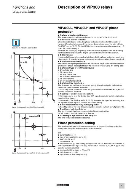
Functions andcharacteristicsDescription of VIP300 relaysDE10324DE10325See also c: indicator reset button.Curve 1: phase setting V IDMT low thresholdVIP300LL, VIP300LH and VIP300P phaseprotectionb 1: phase protection setting zoneThe phase protection settings are located in the top half of the front panel.b 2: threshold overrun indicatorWhen the red indicator blinks, the phase protection low threshold time delay isrunning. When this is the case, if the current does not decrease, the relay will trip.For IDMT curves (SI, VI, EI), the LED lights up when the current is greater than 1.2times the current setting Is.For the IDMT curve (RI), it lights up when the current is greater than the Is setting.For the definite time curve DT, it lights up when the low threshold is overrun.b 3: trip indicatorIt is normally black and turns yellow to indicate that the phase protection has given atripping order. It stays in the same status, even when the relay is no longer energized.b 4: choice of current setting IsThe current setting range depends on the sensor and range used: the selector switchgraduations should be adapted to suit the sensor and range using the setting label.b 5: choice of type of low threshold curvev DT: definite timev SI: inverse timev VI: very inverse timev EI: extremely inverse timev RI: specific curvev off: low threshold disabled.b 6: choice of low threshold I>The threshold is a multiple of the current setting. It is only active for definite timethresholds (selector switch 5 set to DT).If the tripping curve is selected with IDMT (selector switch 5 set to RI, SI, VI, EI), theselector switch has no effect.b 7: setting of low threshold time delay t>If the tripping curve is of the definite time (DT) type, the selector switch sets the lowthreshold time delay.If the curve is of the IDMT type (RI, SI, VI, EI), the value displayed is the tripping timefor a phase current equal to 10 times the current setting.b 8: low threshold time delay multiplying factorIn the x10 position, the time delay displayed on selector switch 7 is multiplied by 10.b 9: setting of high threshold I>>The high threshold is chosen as a multiple of the current setting.In "off" position, the high threshold is disabled.b 10: setting of high threshold time delay t>>The time delay is set directly in seconds.Phase protection settingThe numbers indicated on the curves opposite are those of the phase protectionsetting switches (refer to the diagram of the front view).Curve 2: phase setting V definite time low thresholdSet:b current setting Is (4)b type of low threshold I> curve (5)v IDMT: RI, SI, VI, EIv definite time: DTb low threshold I> (6). This setting is only active if the low threshold curve chosen isof the definite time DT type (curve 2). For the other choices, SI, VI, EI, RI (fig 1), theselector switch is disabled.b low threshold time delay t> (7) and (8)b high threshold I>> (9)b high threshold time delay t>> (10).5