Steca Solar MPPT 2010 - Manual
Steca Solar MPPT 2010 - Manual
Steca Solar MPPT 2010 - Manual
- No tags were found...

Create successful ePaper yourself
Turn your PDF publications into a flip-book with our unique Google optimized e-Paper software.
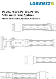
3. Description3.1 FunctionsThe solar charge controller• monitors the battery voltage,• controls the charging process,• controls the connection/disconnection of loads connected to the load output.This optimises battery use and significantly extends its service life.A battery charging algorithm protects the battery from harmful states. Activationof the three deep discharge functions (LVW, LVD and LVR) is dependentUocupon the battery voltage.3.1.1 MPP trackingThis solar charge controller meets the latest technological standards since UBat it isequipped with an optimal MPP tracking algorithm and thus can use at all timesthe maximum available output of the solar module. You will find more detaileddocumentation about MPP tracking in the technical manual; which can be accessedat www.stecasolar.com.10 20 30 40 50 60 70 80 90 100 110 1203.1.2 What is MPP tracking (<strong>MPPT</strong>)?Umpp<strong>MPPT</strong> stands for "Maximum Power Point Tracking". This describes a process bymeans of which the solar module is always operated at the point of maximumpossible power. Because the point the maximum power can vary dependingon the operating mode and the local conditions, and because it changes in thecourse of the day, the term "tracking" is used, i.e. the tracking of this point.3.1.3 When should charge controllers with MPP trackingbe used?Number of solar cells<strong>Solar</strong>zellenkonv. La<strong>MPPT</strong><strong>Solar</strong>zelleU mppU OC<strong>MPPT</strong>Standard chargecontrollerUocUmppU BatUBat010 20 30 40 50 60 70 80 90 100 110 120730.927 | 09.10
3.3 LED displaysLED Status MeaningInfo LED illuminates normal operationgreenflashes red a fault exists (see "Faults and remedies")Red LED flashes quickly battery emptywhen the battery continues to be dischargedthe deep-discharge deactivation is triggeredflashes deep-discharge deactivationYellow LED illuminates battery weakflashes switch-on threshold after deep-discharge deactivationhas not yet been reached1. green LED illuminates battery good2. green LED illuminates battery fullflashes quickly battery full, charge regulation active,i.e. charging current reduced4. InstallationWARNINGDanger of explosion from sparking! Danger of electric shock!<strong>Solar</strong> modules generate electricity under incident light. The full voltage ispresent, even when the incident light levels are low.The solar charge controller may only be connected to the local loads and thebattery by trained personnel and in accordance with the applicable regulations.Follow the installation and operating instructions for all components of thePV system.Ensure that no cables are damaged.At a voltage of > 75 V, particularly with regard to module open circuit voltage(over the entire temperature range), the entire solar energy system mustbe installed with protection class II.Protect the solar modules from incident light during installation, e.g. coverthem.Never touch uninsulated cable ends.Use only insulated tools.Ensure that all loads to be connected are switched off. If necessary, removethe fuse.Connections must always be made in the sequence described below (see4.2.2).730.927 | 09.10
4.1. Mounting the solar charge controller4.1.1 Mounting location requirements• Do not mount the solar charge controller outdoors or in wet rooms.• Do not subject the solar charge controller to direct sunshine or other sourcesof heat.• Protect the solar charge controller from dirt and moisture.• Mount upright on the wall (concrete) on a non-flammable substrate.• Maintain a minimum clearance of 10 cm below and around the device toensure unhindered air circulation.• Mount the solar charge controller as close as possible to the batteries (with asafety clearance of at least 30 cm).4.1.2 Fastening the solar charge controllerMark the position of the solar charge controller fastening holes on the wall.Drill 4 Ø 6 mm holes and insert dowels.Fasten the solar charge controller to the wall with the cable openings facingdownwards, using 4 oval head screws M4x40 (DIN 7996).4.2 Connection4.2.1 Preparing the wiringThe cross section of the connection cables must be suitable for the currents whichoccur.Modulstrom Batteriestrom Laststrom Querschnitt AWG Isolation18 A 20 A 10 A 10 mm 2 8 85°CThe table above applies to the following cable lengths:• 10 m solar module connection cable• 2 m battery connection cable• 5 m load connection cableConsult a dealer if the specified cable lengths are inadequate.An additional 30 A external fuse (not provided) must be connected to thebattery connection cable, close to the battery pole.The external fuse prevents dangerous situations due to cable short circuits. 730.927 | 09.10
4.2.2 Connection2 1 3WARNINGDanger of explosion from sparking! Danger of electric shock!At a voltage of > 75 V, particularly with regard to module open circuit voltage(over the entire temperature range), the entire solar energy system mustbe installed with protection class II.1st step: connect the batteryCAUTIONThe device will be destroyed if the battery is connected with the wrong polarity.Label the battery connection cables as a plus cable (A+) and aminus cable (A–).Lay the battery cables in parallel between the solar chargecontroller and the battery.Connect the battery connection cable with the correct polarity to the middlepair of terminalson the solar charge controller (with the battery symbol).Connect battery connection cable A+ to the positive pole of the battery.Connect battery connection cable A– to the negative pole of the battery.If the connection polarity is correct, the info LED illuminates green.If necessary, remove any external fuse.730.927 | 09.10
2nd step: connect the solar moduleCAUTIONThe connected modules may not exceed an open circuit voltage (VOC) of 100V, even at extremely low temperatures.Ensure that the solar module is protected from incident light.Ensure that the solar module does not exceed the maximumpermissible input current.Label the solar module connection cables as a plus cable (M+)and a minus cable (M–).Lay both solar module connection cables in parallel between the solar moduleand the solar charge controller.First connect the M+ solar module connection cable to the correct poleof the left pair of terminals on the solar charge controller (with the solarmodule symbol), then connect the M– cable.Remove the covering from the solar module.3rd step: connect loadsWARNINGDanger of explosion from sparking! Danger of electric shock! At a voltage of > 75 V, particularly with regard to module open circuit voltage(over the entire temperature range), the entire solar energy system mustbe installed with protection class II.Notes• Connect loads that must not be deactivated by the solar chargecontroller deep discharge protection, e.g. emergency lights orradio connection, directly to the battery.• Loads with a higher current consumption than the deviceoutput can be directly connected to the battery.However, the solar charge controller deep discharge protection will no longerintervene. Loads connected in this manner must also be separately fused. Loadsof this type can also be reliably connected via an additional output relay (e.g.<strong>Steca</strong> PA EV 200 A).Label the load connection cables as a plus cable (L+) and a minus cable (L–).Lay the load connection cables in parallel between the solar charge controllerand the load.10 730.927 | 09.10
First connect the L+ load cable to the correct pole of the right pair of terminalson the solar charge controller (with the lamp symbol), then connectthe L– cable.Replace the load fuse or switch on the load.4th step: final work Fasten all cables with strain relief in the direct vicinity of the solar chargecontroller (clearance of approx. 10 cm).4.2.3 GroundingThe components in stand-alone systems do not have to be grounded – this isnot standard practice or may be prohibited by national regulations (e.g.: DIN57100 Part 410: Prohibition of grounding protective low voltage circuits). Consultthe technical manual for more information.4.2.4 Lightning protectionIn systems subjected to an increased risk of overvoltage damage, we recommendinstalling additional lightning protection / overvoltage protection toreduce dropouts. Consult the technical manual for more detailed information.5. OperationThe solar charge controller immediately begins operation once the battery isconnected or the external fuse is inserted.The display of the solar charge controller shows the current operating mode.User intervention or user settings are not required.Protection functionsThe following integrated protection functions of the solar charge controllerensure that the battery is handled as gently as possible.The following protection functions are part of the basic function of the controller:• overcharge protection• deep discharge protection• battery undervoltage protection• solar module reverse current protectionThe following installation faults do not destroy the controller. After correctingthe fault, the device will continue to operate correctly:• protection from solar module short circuits / incorrect solar module polarity• protection from short circuits at the load output or excessive loadcurrent730.927 | 09.1011
• protection from solar module overcurrent• protection from device overtemperature• protection from overvoltage at the load output• protection from the wrong connection sequence6. MaintenanceThe solar charge controller is maintenance-free. All components of the PVsystem must be checked at least annually, according to the specifications of therespective manufacturers.Ensure adequate ventilation of the cooling element.Check the cable strain relief.Check that all cable connections are secure.Tighten screws if necessary.Terminal corrosion12 730.927 | 09.10
7. Faults and remediesFault Cause RemedyNo displayInfo LED flashesredLoad cannot beoperated or onlyfor a short time+info LED flashesred• Battery voltage too low Pre-charge the battery• The external fuse in the Replace the external fusebattery connection cablehas blown.• Battery is not connected 1. Unclamp all connections• Battery is defective. Connect a (new) batterywith the correct polarity3. Reconnect the solar moduleand loads• Battery is connected with Device may be defective;the wrong polarity Return device to specialistdealer• Charging interrupted due to Charging automaticallyexcessive charging current continues as soon as thecharging current lies withinthe permissible range• Optobus transfer faulty Repeat programming• Battery voltage too low Pre-charge the battery• Battery voltage too high Check installation• Load output is switched Reduce load current, ifoff due to excessive loadcurrentnecessary switch off ordisconnect loads Check loads• Load output is switched off 1. Disconnect loadsdue to short circuit at loadoutput. Correct the cause of theshort circuit3. Reconnect loads• Load output is switched off The load output automaticallyswitches on again oncedue to overheating of thesolar charge controller the solar charge controllerhas cooled down Improve the cooling aircirculation Remove any other heatsources Check the conditions of useand the mounting location730.927 | 09.1013
Load cannot beoperated+info LED flashesred+red battery LEDflashesLoad cannot beoperated+info LED flashesred+2. green LEDflashesLoad cannot beoperated+info LED illuminatesgreenBattery is notchargedBattery displayjumps quickly• Load output is switched The load output automaticallyswitched on again asoff due to too low batteryvoltagesoon as the battery voltagelies within the permissiblerange Pre-charge the battery Equip loads directly connectedto the battery withdeep discharge protection Check the battery andreplace if necessary• Load output is switched The load output automaticallyswitched on again asoff due to excessive batteryvoltagesoon as the battery voltagelies within the permissiblerange• External charging source is Check the external chargingnot voltage-limitedsource If necessary, switch offexternal charging sources• Defective load or installationerror Replace Connect load correctlyload• <strong>Solar</strong> module not connected Connect the solar module• <strong>Solar</strong> module connected Connect the solar modulewith incorrect polarity with the correct polarity• Short circuit at solar module Correct the cause of theinputshort circuit• Incorrect solar module Use a solar module of thevoltagespecified voltage• Device overheated Make sure the device is wellventilated• <strong>Solar</strong> module defective Replace the solar module• Large pulse current Tune the current consumptionto match the batterycapacity• Battery is defective Replace the battery14 730.927 | 09.10
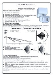
Efficiency example:100 %99 %98 %97 %96 %95 %94 %93 %92 %91 %90 %15 W40 W85 W120 W200 W280W320 W400 W730.927 | 09.1015
8. Technical data<strong>MPPT</strong> <strong>2010</strong>Characterisation of the operating behaviourSystem voltage 12 V (24 V)Rated output 250 W (500 W)Max. efficiency > 98 %Own consumption10 mADC input sideMPP voltage15 V (30 V) < U module 50 % / 12.5 V (25.0 V)Deep discharge protection* (SOC / LVD) < 30 % / 11.5 V (23.0 V)Application conditionsAmbient temperature -25 °C … +40 °CEquipment and designTerminal clamps (fine-wire / single wire) 16 mm 2 / 25 mm 2 - AWG 6 / 4Degree of protection IP 32Dimensions (X x Y x Z)187 x 153 x 68 mmWeightapprox. 900 g* see optionsTechnical data at 25 °C / 77 °F** .CAUTIONIf an open circuit voltage of more than 100 V is supplied to the connected solarmodule, the controller will be destroyed. When selecting the solar module, itis important to bear in mind that the open circuit voltage should never exceed100 V over the entire working temperature range.When using solar modules with a maximum open circuit voltage of between75 and 100 V (over the entire temperature range), all installation steps must becarried in accordance with protection class II.16 730.927 | 09.10
18 730.927 | 09.10
730.927 | 09.1019
730927