Refrigeration Manual - HVAC and Refrigeration Information Links
Refrigeration Manual - HVAC and Refrigeration Information Links
Refrigeration Manual - HVAC and Refrigeration Information Links

You also want an ePaper? Increase the reach of your titles
YUMPU automatically turns print PDFs into web optimized ePapers that Google loves.
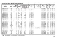
suction-cooled, water-cooled, high temperature, mediumtemperature, low temperature, R-12, R-22, or R-502applications as required. Obviously on many applicationsthere will be a greater safety factor than on others.This does not mean that every compressor may beoperated continuously at a load greatly in excess of itsnameplate rating without fear of failure. Motor amperageis only one factor in determining a compressor’s operatinglimitations. Discharge pressure <strong>and</strong> temperatures,motor cooling, <strong>and</strong> torque requirements are equallycritical. Safe operating limits have been establishedfor each compressor, <strong>and</strong> are published on compressorspecification sheets.VOLTAGE AND FREQUENCYAlthough electric energy distributed in the United Statesis 60 cycle, distribution voltages are not st<strong>and</strong>ardized.Single phase voltages may be 115, 208, 220, 230, or240, <strong>and</strong> most utilities reserve the right to vary thesupply voltage plus or minus 10% from the nominalrating. Three phase voltage may be 208, 220, 240, 440,460, or 480, again plus or minus 10%. Unless motorsare specifically designed for the voltage range in whichthey are operated, overheating may result.Most motors may be operated at the voltage on themotor nameplate, plus or minus 10% without dangerof overheating, but in order to allow more flexibility ofoperation, extended voltage range motors are now beingdeveloped where the usage warrants this action. Forexample, a three phase motor nameplated 208/240 voltsis satisfactory for operation from 187 volts to 264 volts,<strong>and</strong> a three phase motor nameplated 440/480 volts maybe operated from 396 volts to 528 volts.In many parts of the world, the electrical power supplyis 50 cycle rather that 60 cycle. If both voltage <strong>and</strong>frequency supplied to a motor vary at the same rate,operation of a given motor at the lower frequencycondition within narrow limits is satisfactory in somecases. For example, a 440 volt, 3 phase, 60 cycle motorwill operate satisfactorily on 380 volt, 3 phase, 50 cyclepower supply.However, in some 50 cycle applications, the relationshipbetween voltage <strong>and</strong> frequency is such that st<strong>and</strong>ard60 cycle motors cannot be used unless the motorcharacteristics are suitable for 50 cycle operation, <strong>and</strong>this can be determined only by test. On most singlephase 50 cycle applications, specially wound 50 cyclemotors are required.THREE PHASE MOTORSThree phase motors are wound with 3 separate windingsor phases. Each of the windings is 120° out of phase withthe other windings, which results in a very high startingtorque motor requiring no supplemental mechanismsor devices for starting. The direction of rotation ofthe motor may be changed by reversing any two lineconnections.Because three phase motors can utilize smaller wire sizes<strong>and</strong> therefore are smaller, they are used on almost allapplications larger than 5 HP, <strong>and</strong> if three phase poweris available, are frequently preferred for any load largerthan fractional horsepower applications.SINGLE PHASE MOTORSA single phase motor has but one running winding orphase, <strong>and</strong> basically is not a self starting motor. Oncestarted, it will run as a pure induction motor. In orderto provide starting torque, a second winding called thestarting winding is provided, which normally has greaterresistance than the running winding. The differentvariations of single phase motors are primarily due tothe different starting arrangements used.If the start winding remains in the circuit during operationit would be damaged by excessive heat. Therefore, thestarting winding is removed from the circuit as the motorapproaches rated speed by either a potential relay, acurrent relay, or a centrifugal switch.A current relay is normally open when de-energized,<strong>and</strong> the coil is wound so that the contacts will closewhen starting current is being drawn by the motor, butwill drop out when the current approaches normal fullload conditions. Therefore, the current relay is closedonly during the starting cycle.A potential relay is normally closed when de-energized,<strong>and</strong> the coil is designed to open the contacts only whensufficient voltage is generated by the start winding. Sincethe voltage or back-EMF generated by the start winding isproportional to the motor speed, the relay will open onlywhen the motor has started <strong>and</strong> is approaching normalrunning speed. The illustrations show the schematicwiring with the motor in operation so the potential relayis in the energized position.SPLIT PHASE MOTORSOn a split phase motor, the running winding <strong>and</strong> startwinding are in parallel, <strong>and</strong> are spaced 90° apart. The© 1967 Emerson Climate Technologies, Inc.All rights reserved.9-3