Section 10STARTING EQUIPMENT AND MOTOR PROTECTORSSince hermetic motors must operate under a wide rangeof operating conditions, <strong>and</strong> vary in size from fractionalhorsepower to 35 HP <strong>and</strong> larger, a wide variety of startingequipment is used.CONTACTORS AND STARTERSA contactor is a load current carrying device, which makes<strong>and</strong> breaks to start <strong>and</strong> stop the compressor motor. Astarter is merely a contactor with motor protective devicesmounted in a common enclosure.On single phase motors up to 3 HP in size, the motorcurrent is often low enough to be h<strong>and</strong>led by the contactsin the low pressure control or thermostat, <strong>and</strong> no separatecontactor is required. As the motor size increases, theamperage draw increases beyond the range of smallcontrol apparatus, <strong>and</strong> the motor current must be h<strong>and</strong>ledthrough the contacts of a starter or contactor, while thecontrol makes <strong>and</strong> breaks a pilot circuit which energizesthe coil of the contactor .For motor-compressors whose power requirementsare such that contactors are required, it is essentialthat the contactors used are adequately sized for theattached load. The rating of the contactor for both fullload amperes <strong>and</strong> locked rotor amperes must be greaterthan the nameplate rating of the motor-compressor plusthe nameplate rating of any fans or other accessoriesalso operated through the contactor .NEMA general purpose type contactors are built for themost severe industrial usage, <strong>and</strong> are designed for aminimum life of 2,000,000 cycles. Because they mustbe adaptable to any usage, general purpose contactorshave a large safety factor, <strong>and</strong> as a result are bothlarge <strong>and</strong> costly. For refrigeration <strong>and</strong> air conditioningapplications, a life of 250,000 cycles is entirely adequate,so the physical construction can be lighter, <strong>and</strong> the costof the contactor correspondingly less.To meet the specific needs of the refrigeration <strong>and</strong> airconditioning industry, electrical equipment manufacturershave developed definite purpose contactors. Thesecontactors are rated in amperes, <strong>and</strong> when selectedproperly for the load, are smaller <strong>and</strong> more economicalthan the general purpose contactor. Since compressorcontactors are frequently subjected to quick recycling,the contacts must be large enough for satisfactory heatdissipation in order to prevent contactor overheating.Overheating of the contacts may cause sticking <strong>and</strong>single phasing, <strong>and</strong> can cause a motor failure eventhough the motor overload protectors trip <strong>and</strong> open thecontrol circuit.In order to insure that definite purpose contactorsare properly applied to Copel<strong>and</strong>® br<strong>and</strong> motorcompressorswith pilot circuit protection, the contactormust meet Emerson Climate Technologies, Inc. minimumperformance requirements.CAPACITORSAn electrical capacitor is a device which stores electricalenergy. They are used in electric motors primarily todisplace the phase of the current passing through thestart winding. While a detailed study of electrical theoryis beyond the scope of this manual, capacitors in amotor circuit provide starting torque, improve runningcharacteristics <strong>and</strong> efficiency, <strong>and</strong> improve the powerfactor.The amount of electrical energy a capacitor will holddepends on the voltage applied. If the voltage isincreased, the amount of electrical energy stored in thecapacitor is increased. The capacity of a capacitor isexpressed in microfarads (MFD) <strong>and</strong> is dependent onthe size <strong>and</strong> construction of the capacitor.The voltage rating of a capacitor indicates the nominalvoltage at which it is designed to operate. Use of acapacitor at voltages below its rating will do no harm. Runcapacitors must not be subjected to voltages exceeding110% of the nominal rating, <strong>and</strong> start capacitors must notbe subjected to voltages exceeding 130% of the nominalrating. The voltage to which a capacitor is subjected is notline voltage, but is a much higher potential (often calledelectromotive force or back EMF) which is generatedin the start winding. On a typical 230 volt motor, thegenerated voltage may be as high as 450 volts, <strong>and</strong>is determined by the start winding characteristics, thecompressor speed, <strong>and</strong> the applied voltage.Capacitors, either start or run, can be connected eitherin series or parallel to provide the desired characteristicsif the voltage <strong>and</strong> MFD are properly selected. When twocapacitors having the same MFD rating are connectedin series, the resulting total capacitance will be one halfthe rated capacitance of a single capacitor. The formulafor determining capacitance (MFD) when capacitors areconnected in series is as follows:© 1967 Emerson Climate Technologies, Inc.All rights reserved.10-1
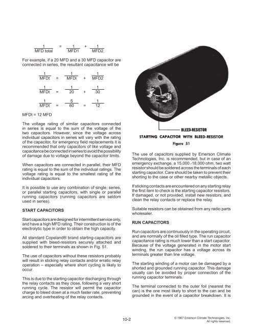
1 = 1 + 1MFD total MFD1 MFD2For example, if a 20 MFD <strong>and</strong> a 30 MFD capacitor areconnected in series, the resultant capacitance will beMFDt = 12 MFD1 1 1MFDt = MFDl + MFD21 1 1MFDt = 20 + 301 5 1MFDt = 60 = 12The voltage rating of similar capacitors connectedin series is equal to the sum of the voltage of thetwo capacitors. However, since the voltage acrossindividual capacitors in series will vary with the ratingof the capacitor, for emergency field replacements it isrecommended that only capacitors of like voltage <strong>and</strong>capacitance be connected in series to avoid the possibilityof damage due to voltage beyond the capacitor limits.When capacitors are connected in parallel, their MFDrating is equal to the sum of the individual ratings. Thevoltage rating is equal to the smallest rating of theindividual capacitors.It is possible to use any combination of single, series,or parallel starting capacitors, with single or parallelrunning capacitors (running capacitors are seldomused in series).START CAPACITORSStart capacitors are designed for intermittent service only,<strong>and</strong> have a high MFD rating. Their construction is of theelectrolytic type in order to obtain the high capacity.All st<strong>and</strong>ard Copel<strong>and</strong>® br<strong>and</strong> starting-capacitors aresupplied with bleed-resistors securely attached <strong>and</strong>soldered to their terminals as shown in Fig. 51.The use of capacitors without these resistors probablywill result in sticking relay contacts <strong>and</strong>/or erratic relayoperation – especially where short cycling is likely tooccur.This is due to the starting capacitor discharging throughthe relay contacts as they close, following a very shortrunning cycle. The resistor will permit the capacitorcharge to bleed down at a much faster rate, preventingarcing <strong>and</strong> overheating of the relay contacts.The use of capacitors supplied by Emerson ClimateTechnologies, Inc. is recommended, but in case of anemergency exchange, a 15,000 -18,000 ohm, two wattresistor should be soldered across the terminals of eachstarting capacitor. Care should be taken to prevent theirshorting to the case or other nearby metallic objects.If sticking contacts are encountered on any starting relaythe first item to check is the starting capacitor resistors.If damaged, or not provided, install new resistors, <strong>and</strong>clean the relay contacts or replace the relay.Suitable resistors can be obtained from any radio partswholesaler.RUN CAPACITORSRun capacitors are continuously in the operating circuit,<strong>and</strong> are normally of the oil filled type. The run capacitorcapacitance rating is much lower than a start capacitor.Because of the voltage generated in the motor startwinding, the run capacitor has a voltage across itsterminals greater than line voltage.The starting winding of a motor can be damaged by ashorted <strong>and</strong> grounded running capacitor. This damageusually can be avoided by proper connection of therunning capacitor terminals.The terminal connected to the outer foil (nearest thecan) is the one most likely to short to the can <strong>and</strong> begrounded in the event of a capacitor breakdown. It is10-2© 1967 Emerson Climate Technologies, Inc.All rights reserved.


