1301043905-SPACEAGE SWITCHGEARS.pdf - Industrial Products
1301043905-SPACEAGE SWITCHGEARS.pdf - Industrial Products
1301043905-SPACEAGE SWITCHGEARS.pdf - Industrial Products
- No tags were found...

Create successful ePaper yourself
Turn your PDF publications into a flip-book with our unique Google optimized e-Paper software.
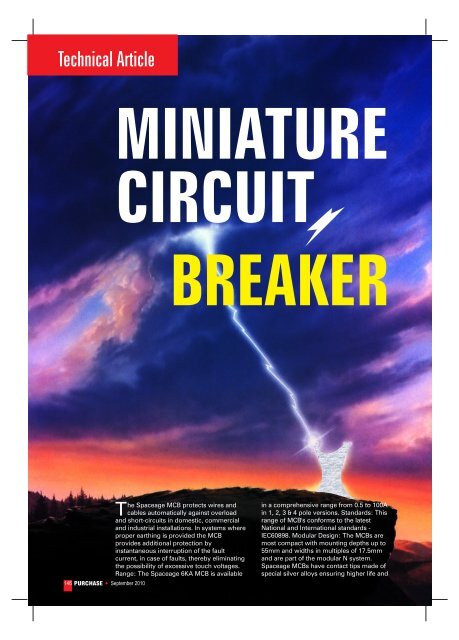
Electrical & ElectronicsIndustry Reviewmaximum safely against contact welding.These contacts have low contact resistanceresulting in reduced voltage drop and a verylow watt loss leading to energy savings.Short Circuit Breaking Capacity: 6 kA & 10 kAType Classification: B & CRated Voltage: 240 / 415 V: 50 HZRef. Ambient Temperature: 50ºC100 AMP MCB & 125 AMP ISOLATOR100 Amp MCB & 125 Amp ISOLATOR hasbeen designed keeping in mind thecustomer needs. The features are as underConforms to IEC 60898-95.We have maintained standard thicknessof 17.5mm, similar to lower rating of MCB(0.5 A to 63 A) to facilitate easy mounting inany Distribution Box.Box type terminal has been designed foreasy termination of cable up to 50 mm2.Heavy duty screws have been provided forbetter tightening of contacts.Heavy duty ETP copper terminals andextra thick silver inlaid contacts ensure lowtemperature rise and low watt loss.Causes of Short circuit and overloadscan be mounted on standard 35mm DIN Railby snap action. No time wastage in installingand replacing the MCB.SHOCK PROOF: Finger and hand touch safe.Tested as per IEC Pub 60898 (1995) & IEC-60898-1, 2002 protection against electricshock.HOUSING: The housing of <strong>SPACEAGE</strong> MCBis injection moulded from special grade PBTas per international specifications. Thehousing and other moulded components arefire retardant, anti-tracking and nonhygroscopic. The housing can with standhigh temperature and is impact resistant.CONTACTS: Contacts are made of specialsilver inlaid into copper strip, ensuringhigher life and maximum safety againstcontact welding and erosion. These contactshave low contact resistance resulting inreduced watt loss. The contacts aredesigned to have zero Bounce duringclosing operation.CURRENT LIMITING ACTION: The high speedcurrent limiting action ensures that the MCBoperate before the full prospective faultcurrent is allowed to develop. Under faultconditions, damage can be sustained to theinstallation and associated equipment due toSALIENT FEATURESCONFORMS TO LATEST STANDARD<strong>SPACEAGE</strong> MCB conform to the lateststandard IEC Pub 60898 (1995) in selectedratings. CE MARKING fulfills the requirementof global standards.ENERGY SAVING: The low power loss asstipulated in the IEC 60898/95 has beentaken care of in designing the <strong>SPACEAGE</strong>MCB. Low power loss figures of <strong>SPACEAGE</strong>MCB contributes significantly to the energysaving.DIN RAIL MOUNTING: <strong>SPACEAGE</strong> MCB'sthe amount of energy that passes before thecurrent is completely interrupted. The totalSeptember 2010 PURCHASE 147
Industry ReviewElectrical & Electronics148 PURCHASE September 2010energy Let through depends on the value ofcurrent and the time for which it flows, andis denoted by the symbol I2t. The high speedcurrent limiting action of <strong>SPACEAGE</strong> MCBensures that the energy let through and anysubsequent damage is minimized. Thisreduced LET THROUGH ENERGY (Class 3 asper BS EN 60898) assists greatly with bothback-up and discrimination considerations.OPERATING MECHANISM: <strong>SPACEAGE</strong> MCBhave a quick make & break Trip FreeMechanism. In the even t of an over currentor short circuit the MCB automaticallyinterrupts all poles even if the MCB toggle isheld in ON position, the handle alwaysindicates the correct contact position.MODERATE OVERLOAD CONDITION:Detection of moderate over load conditionsis achieved by the use of a Bimetal OverloadRelay, which deflects inresponse to the currentpassing through it. TheBimetal Relay movesagainst the trip barreleasing the tripmechanism.SHORT CIRCUITCONDITIONS: When thecurrent flowing through the MCB reaches apredetermined level, the solenoid inMagnetic Coil directly pulls in the plunger,which releases the trip mechanism.PERFECT CONNECTIONS: The design ofterminals makes the wiring easier.Combination box type terminals withcombination head screws on both sides withdeep serrations ensure sparkless and firmconnections. The bi-connection facilitysimplifies connection in various applicationareas.LOW WATT LOSS: <strong>SPACEAGE</strong> MCBs havebeen designed to minimize energy lossthrough unique contact configuration &reduction of hot spots. Watt loss per pole in<strong>SPACEAGE</strong> MCB is far lower than thatspecified in, IEC: 60898POTENTIAL FREE DIN CLIP: The allinsulated DIN clip ensures electrical safetyand high mechanical strength.WORKING PRINCIPLE: <strong>SPACEAGE</strong> MCB is ahigh fault capacity, thermal-magnetic type ofbreaker. It protects against overload andshort circuit. Over load protection isachieved with a thermal bi-metal strip whichgets heated in case of overload and in turnpushes the trip latch which releases thecontacts and the operating knob is switchedto Mid Trip Position clearly indicating thefault.In case of short circuit the high faultcurrent energizes the magnetic coil resultingin plunger striking the trip lever whichensures immediate release of trippingmechanism and the operating knob isswitched to Mid TripPosition.TRIPPINGCHARACTERISTICS:RECOMMENDEDAPPLICATIONS:B TYPE: forprotection ofResistive load suchas bulb, heater etc.C TYPE: forprotection of Inductive load such as motor,air conditioner etc.MCB - TPN 100 AMPAUXILIARY SWITCH<strong>SPACEAGE</strong> MCB with Auxiliary SwitchAuxiliary switch can be supplied factory
Electrical & ElectronicsIndustry ReviewWIRINGDIAGRAMfitted withany MCB(SP, SPN,DP, TP, TPN,and FP) togiveindicationof 'ON' or'OFF'position ofMCBFUNCTION:Theauxiliaryswitch isused forremote indication of the circuit condition(ON/OFF) of the MCB. All the connectingterminals are easily accessible from the topposition. The auxiliary switch is connected tothe tripping mechanism of MCB andoperates along with MCB. That it is switchedON and OFF together with the MCB throughthe connector. It is available in factory fittedmodule. This can be used in followingoutgoing combination modes dependingupon user requirement.ISOLATORSpecifications: IEC-60947-3, 1999Number of Poles: SP, DP, TP & FPUtilization Category: AC23ARated Voltage: 240 / 415 V ACRated Currents: 16 to 125 Amps.TECHNICAL DATASpecifications: IEC Pub 60898Number of Poles: 1, 1+N, 2, 3, 3+N & 4Tripping Characteristic & Rated: Bcharacteristics- 0.5A to 100 ACurrents (In): C characteristics - 0.5A to 100ARated breaking capacity (Icn): 10,000 AEnergy Limiting Class: Class 3 as per BS EN60898Rated Voltages (Ue) Single Pole: 240 / 415VACMulti Pole: 415 VACInsulation Voltage (Ui): 500VRated Frequencies: 50/60 HzImpulse withstands voltage (Uimp): 4 KV(1.2 μ)Impulse power frequency voltage: 2 KV (50Hz)Housing material: PolybutyleneTerephthalate in Grey colourDegree of Protection: IP 20 as per IEC 60529MountingPosition: AnypositionMounting: Quick snap to mounting rails, 35mmConnecting Terminals: Combination boxterminals on incoming and outgoing sides.Suitable for single-core, stranded andflexible conductors up to 25 sq mm,Combination crosshead screw, max.Tightening torque 2 NmElectrical Service Life: Min. 30,000make/break operationsAmbient Temperature: T max. : +55º C, Tmin.: -25º CImpactResistance:3g, At least2 impactsduration 13msTRIPPING CHARACTERISTICS CURVESSeptember 2010 PURCHASE 149
Industry ReviewElectrical & ElectronicsFrom: - Suresh Duggal (General Manager)<strong>SPACEAGE</strong> <strong>SWITCHGEARS</strong> LTD68, IDC, Mehrauli RoadGurgaon-122001150 PURCHASE September 2010