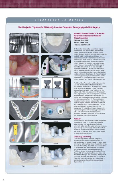
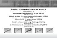
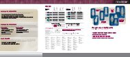
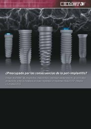
T E C H N O L O G Y I N M O T I O NThe Navigator System For Minimally Invasive Computed Tomography Guided SurgeryImmediate Provisionalization Of A Two-UnitRestoration In The Posterior Mandible:A Case Presentation† Michael Block, DMD‡ Marco Brindis, DDS+ Paulino Castellon, DDSFigure 1Figure 2Figure 3Figure 4Figure 5Figure 7Figure 8Figure 9Figure 10Figure 11CT (Computed Tomography) guided dental implantplacement has been introduced due to an elevatedinterest by clinicians to perform minimally invasiveimplant placement protocols thus reducing post-operativemorbidity and to provide patients with same dayrestorative solutions. In clinical situations where thereis limited bone height above the inferior alveolar canalor under the maxillary sinus, the accuracy by whichimplant placement can be performed with CT guidedimplant placement is a valuable tool. Additionally, theinformation derived from the CT scan affords theopportunity to fabricate a working cast with implantanalogs using the surgical guide. The position of theanalogs in the cast matches the predetermined implantpositions planned in the software. On this working cast,a laboratory processed provisional restoration can beprefabricated for immediate placement at the time ofimplant placement with minimal chairside adjustment.The Clinical Case Presentation to follow demonstratesa 58-year-old male patient who presented with anon-restorable mandibular left second premolar and firstmolar secondary to caries and fracture. The patientrequested treatment which would “minimize my timewithout teeth in this area, and avoid swelling and painwhich might keep me from my employment.” To realizethe patient’s goals, the teeth were extracted and thesockets were grafted with mineralized bone in anticipationof implant placement (Figure 1). Three months later,clinical examination revealed adequate ridge width andheight for implant placement. A CT scan was obtained,reformatted with virtual implants placed and a surgicalguide was fabricated. One month later, with theassistance of CT guided dental implant placement, twoimplants were placed and immediately provisionalizedwith a fixed, non-occlusally loaded provisionalrestoration. The patient was able to return to work thenext day without discomfort or swelling.TreatmentA sulcular incision was made with anterior and posteriorvertical release. Teeth #’s 19 and 20 were removedusing sectioning techniques because of ankylosisof the teeth to the bone. The buccal bone was preserved.Approximately 1cc of University of Miami Tissue Bankmineralized allograft bone (300-500 micron diameter)was placed into the sites, which was primarily coveredby advancing the buccal tissue.CT Scanning And PlanningThree months post tooth extraction and grafting(Figure 2), a CT scan was obtained with 1mm thickaxial sections and the occlusal plane at a 0 gantry angle,following the radiographic protocol of Materialise Dental,Inc. (Glen Burnie, MD). The DICOM data was placed ona CD, which was then processed using SimPlant ProInteractive CT Planning Software from Materialise.The inferior alveolar nerve was labeled on the CT scan(Figures 3 & 4). Two virtual implants were placed intothe reformatted images. The relationship of the plannedimplants to the nerve and cortical bone can be seen inFigure 5. A mandibular cast was sent to Materialise tofacilitate fabrication of a tooth borne surgical guide(Figures 6 and 7).Figure 6Figure 126
T E C H N O L O G Y I N M O T I O N C O N T I N U E DFabrication Of A Provisional RestorationThe appropriate diameter and length analog mounts wereselected from the Navigator Laboratory Kit. Two holeswere created in the master cast to accept the implantlaboratory analogs (Figure 8). The appropriate sized analogmounts were inserted into the master tubes. The analogswere attached and the rotational positioning grooves wereengaged with each analog mount to establish the properalignment of the hexes from the cast to the mouth. Thethumb screws on the analog mounts were tightened into theanalogs (Figure 9). The analogs were secured with stone tothe cast using the surgical guide to accurately position theanalogs. After the stone hardened, the thumb screws of theanalog mounts were loosened and the surgical guide wasremoved leaving the analogs in the cast (Figure10).PreFormance ® Posts consistent with the restorative seatingplatforms of the implants, were selected for use as interimabutments. The provisional abutments were placed into theanalogs in the cast (Figure 11). These were prepared onlyto locate the margins in the desired location (Figure 12).A two-unit fixed acrylic provisional restoration was thenfabricated without occlusal contacts (Figures 13 and 14).† Professor Department of Oral and Maxillofacial Surgery, Louisiana State University, School of Dentistry, New Orleans, LA‡ Senior Resident Department of Prosthodontics, Louisiana State University, School of Dentistry, New Orleans, LA+ Associate Professor Department of Prosthodontics, Louisiana State University, School of Dentistry, New Orleans, LAFigure 13Figure 19Implant Placement And ProvisionalizationThe keratinized gingiva on the crest was bisected and alimited periosteal reflection was made. Small vertical releaseincisions were made anteriorly and posteriorly, allowing afull thickness flap to be reflected to the buccal and lingualcrests. The flap was made to insure that the keratinizedgingiva would surround the implant abutments. A tissuepunch would have eliminated the 4mm wide band ofkeratinized gingiva.The surgical guide was placed over the teeth (Figure 15).It was stable and without movement. The Drill PositioningHandles and twist drills (Figure 16) were selected fromthe Navigator Surgical Kit using the drill sequenceinstructions from Materialise to prepare the osteotomies.The twist drills used in the premolar site were 2mm and3.25mm diameter for a 4mm diameter implant and in themolar site, 2mm, 3.25mm and 4.25mm diameter drills wereused for placement of a 5mm diameter implant (Figure 17).The proper implant mount for each implant was selectedfrom the kit and placed on the implants according to theinstructions received. A 4mm diameter x 11.5mm lengthfull OSSEOTITE ® Certain ® Implant was placed first in thepremolar site, followed by placement of a 5mm diameterx 11.5mm length implant in the molar site (Figure 18).The implants were placed with the rotational positioninggroove on the implant mounts aligned with the groovein the surgical guide master tubes to transfer the properalignment of the hexes from the master cast to themouth (Figure 19). The implant mounts were removedby loosening the retaining screw and the gentle elevationof the mount from the master tube. The surgical guidewas then removed (Figure 20).The prepared interim abutments were placed and securedwith titanium abutment screws, which were hand tightened(Figure 21). The fixed provisional restoration was tried inand found to fit without adjustment. There were no centric,working or balancing side contacts. A radiograph wastaken and the provisional restoration was cemented withtemporary cement (Figures 22 and 23). The flaps wereclosed using interrupted 4-0 chromic sutures. The patientwas dismissed with instructions to maintain a soft diet andoptimal self care.The patient was seen seven days following surgery for postoperativeevaluation (Figure 24). Healing was uneventful andthe patient required only ibuprofen for minor discomfort. Hewas able to return to work the day following surgery withoutpain, ecchymosis or swelling. The definitive prosthesis willbe placed in approximately four months.Figure 14Figure 15Figure 16Figure 17Figure 20Figure 21Figure 22Figure 23Figure 18Figure 247