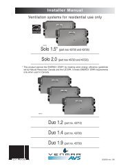
Installation Manual - Venmar
Installation Manual - Venmar
Installation Manual - Venmar

You also want an ePaper? Increase the reach of your titles
YUMPU automatically turns print PDFs into web optimized ePapers that Google loves.
5. INSTALL MOUNTING BRACKET! WARNINGWhen building framework, always follow all applicable construction codes andstandards.1. Modify ceiling stucture at hoodlocation. Install 2" x 4" crossframing between ceiling joistsusing ceiling mounting bracketdimensions shown at right. Theframework must be sized tosupport the total weight of thehood and should not be largerthan 9¾" x 9¾".10¼"FRAMING INNER EDGEMAX. 9¾"10¼"9 3 ⁄8" 10 3 ⁄8"9 3 ⁄8"10 3 ⁄8"HK0062ACEILINGJOISTS2. Finish ceiling surface. Be sure tomark the location of the ceilingjoists and cross framing. Bringhouse wiring through finishedceiling.CROSSFRAMINGHD0432HOUSEWIRING- 7 -
5. INSTALL MOUNTING BRACKET (CONT’D)8" ROUNDDUCTWORK3. Position the mounting bracket insuch a way that one of the sideswithout a “T” will be facing thefront of the hood. Secure mountingbracket to the ceiling using8 no. 10 x 1½" wood screws(2 for each corner). Make surescrews are driven into the centerof the framing for maximumstrength.FRONTOF THE HOODCEILINGMOUNTINGBRACKETHD0442- 8 -
6. ASSEMBLE ANGLE BRACKETS1. Assemble 4 angle brackets tothe ceiling mounting bracketusing at least two no.10-32 x 1/2"quadrex screws per angle bracket.NOTES: 1. Do not tighten thescrews yet.2. Depending on theheight needed (C)(previously determinedin section 4), theangle bracketsmight not touch theceiling as illustratedat right.2. If need be, assemble a secondset of 4 angle brackets to theinner side of the upper anglebracket set according to theheight needed (C) (previouslydetermined in section 4). Use atleast two no. 10-32 x 1/2" quadrexscrews and two no. 10-32 lock nutsper angle bracket connection.NOTE: Do not tighten thescrews yet.FOR 10-FT CEILINGS:Both lower and upper flues areincluded with the hood, but fora 10-ft ceiling, discard theprovided upper flue and usethe optional extension flue, partno. 19325 (sold separately).4 additional angle brackets andadditional mounting hardwareare included with the optionalextension flue.If need be, assemble a third setof 4 angle brackets to the secondangle bracket set according to theheight needed (C) (previouslydetermined in section 4). Useat least two no. 10-32 x 1/2"quadrex screws and two no. 10-32lock nuts per angle bracket.NOTE: Do not tighten thescrews yet.3. Attach blower box assembly tolower angle brackets using at leasttwo no. 10-32 x 1/2" quadrexscrews per angle bracket.FRONTOF THE HOODHD0444ELECTRICAL BOXFOR 10-FTCEILINGS(IF NEED BE)NOTES: 1. Make sure the blower box bottom is at the desired height (C) as previously determinedin section 4.2. Ensure electrical box is positioned in the back right corner.- 9 -
6. ASSEMBLE ANGLE BRACKETS (CONT’D)SIDE VIEWS OF THE BLOWER BOX4. Make sure all brackets are straightand blower box is level and square(as shown at right), then tighten allscrews.FRONTOF THEHOODFRONTOF THEHOODCORRECTINCORRECT7. CONNECT WIRINGHD0420! WARNINGRisk of electric shock. Electrical wiring must be done by qualified personnel inaccordance with all applicable codes and standards. Before connecting wires,switch power off at service panel and lock service disconnecting means toprevent power to be switched on accidentally.1. Remove electrical box cover both retainingscrews. Set cover and screws aside.SCREW LOCATIONSHD04412. Install wire clamp (included) on top ofblower box.Attach the adapter/damper to the blowerbox using 4 no. 8 x 3/8" quadrex screws(included). Remove tape on damper.(Angle brackets not illustrated to easeunderstanding).HJ0068- 10 -
7. CONNECT WIRING (CONT’D)3. Run house wiring through wire clamp andinto blower box electrical box. Tighten wireclamp to secure house wiring cable toblower box.4. Measure the required length of 8" roundmetal duct from the adapter/damper to theductwork rough-in in the ceiling. Connectthis section of duct to the adapter/damper,then connect to ceiling duct and seal bothjoints with metal foil duct tape.HOUSEWIRINGHD04345. Connect hood power cable to house wiringusing provided wire connectors: BLACK toBLACK, WHITE to WHITE and GREEN orBARE wire to GREEN ground screw. DONOT FORGET TO CONNECT THEGROUND.6. Reinstall electrical box cover using bothscrews previously removed.HE0126- 11 -
8. INSTALL GLASS PANELS (WG MODEL ONLY)The WG hood model glass panels are sold separately and have to be installed before completingthe hood installation.For each glass panel:1. Remove glass panel from its packaging.Remove glass panel nuts (factory installed) from both studs and set aside.2. Insert glass panel studs in appropriate hoodholes (some parts not illustrated to easeunderstanding).NOTE: Install the glass panel with the controlpictograms on the front of the hood.3. While holding glass panel, pre-tighten previouslyremoved nuts by hand. Ensure glass panel iscentered.Then, using a 3/8" socket, tighten nuts completely.NUTGLASS PANELSTUD9. INSTALL HOODHD0438! WARNINGBE CAREFUL when installing the decorative flue and hood, they may havesharp edges.CAUTIONDO NOT REMOVE the protective plastic film covering the decorative flue (upperand lower) yet.11. Slide the upper flue up to the ceiling and secure it tothe ceiling mounting bracket using 2 no. 8 x 1/2"quadrex screws.NOTE: Ensure upper and lower flue seams arealigned 1 .Carefully slide the lower flue over the upper flue upto the ceiling and have the second person hold it tothe ceiling 2 while performing step 2.2- 12 -HD0435
9. INSTALL HOOD (CONT’D)SCREW LOCATIONS2. Slide hood over blower box andattach to blower box using the4 screws previously removed fromstep 3.3 (some parts not illustrated toease understanding).NOTE: For more convenience, a total of16 holes (4 holes per section)are available to secure thehood, but only 1 screw persection is necessary.HD04333. Slide the lower flue down on topof the hood. Remove protectiveplastic film from flues.HE01254. Connect blower and power cord back.- 13 -
10.REINSTALL BAFFLE FILTERSCAUTIONRemove protective plastic film covering filters before reinstalling them.1. Using a Phillips no. 2 screwdriver, assembletwo knobs to each filter. The screws MUSTBE on filter tabs side. See illustration atright.HO01932. Rest rear filters edge on filter springs inthe range hood. Using knob, tilt up the filtersinto position. Make sure filter tabs aresecurely engaged in range hood frontedge after installation.FILTER TABS11. LIGHT BULBSHO0195This range hood requires two 120 V, 50 W max., type MR16 with GU10 base, shielded halogenbulbs (included).! WARNINGDo not touch lamps during or soon after operation. Burns may occur. In orderto prevent the risk of personal injury, only install shielded halogen lamps. Also,never install a cool beam, a dichroïc lamp, a lamp not suitable for use inrecessed luminaires or identified for use in enclosed fixtures.To replace bulbs:1. Gently push upward and turncounterclockwise to disengage bulbleads from their grooves.2. Place the new bulb leads into theirgrooves in the socket.3. Gently push upward and turnclockwise until secured.1 2 3NOTE: If need be, use a rubber dishwashing glove to add grip when removing the bulb.- 14 -
12. CARE!WARNINGBefore servicing or cleaning the unit, switch power off at service panel and lockservice panel to prevent power from being switched on accidentally. When theservice disconnecting means cannot be locked, securely fasten a prominentwarning device, such as a tag, to the service panel.BAFFLE FILTERSBaffle filters should be cleaned monthly. Remove baffle filters by pushing them towards the backof hood and rotating downward. Use a warm detergent solution to clean the filters. Let them dryand reinstall them.Baffle filters are dishwasher safe. Clean all-metal filters in the dishwasher using a non-phosphatedetergent. Discoloration of the filter may occur if using phosphate detergent or as a result of localwater conditions — but this will not affect filter performance. This discoloration is not covered bythe warranty.INTERIOR BLOWERRemove the filters in order to access the blower. Vacuum blower to clean. Do not immerse in water.STAINLESS STEELDo:• Regularly wash with clean cloth or ragsoaked with warm water and mild soap orliquid dish detergent.• Always clean in the direction of original polishlines.• Always rinse well with clear water (2 or 3times) after cleaning. Wipe dry completely.• You may also use a specialized householdstainless steel cleaner.Don’t:• Use any steel or stainless steel wool or anyother scrapers to remove stubborn dirt.• Use any harsh or abrasive cleansers.• Allow dirt to accumulate.• Let plaster dust or any other constructionresidues reach the hood. Duringconstruction/renovation, cover the hood tomake sure no dust sticks to stainless steelsurface.GLASS PANELHot water with mild soap or glass cleaner is all that is usually needed.When using mild soap, rinse with clear water. Wipe dry with a clean, soft cloth to avoid watermarks.Avoid when choosing a detergent:- Any cleaners that contain bleach will attack stainless steel.- Any products containing: chloride, fluoride, iodide, bromide will deteriorate surfaces rapidly.- Any combustible products used for cleaning such as acetone, alcohol, ether, benzol, etc., arehighly explosive and should never be used close to a range.13. OPERATIONAlways turn your blower on before you begin cooking to establish an air flow in the kitchen. Let theblower run for a few minutes to clear the air after you turn off the range.CAUTIONAfter a power failure or during the range hood power up, a 5-second bootingsequence is executed. Wait for the control backlighting to turn off before use.NOTE:Due to the particular sensitivity of the control interface, keep the glass panel clean as dirtand condensation may cause erratic operation of the hood blower and/or lighting. If thissituation occurs, wipe the glass panel and wait 90 seconds. Then, adjust the blowerand/or lighting at your convenience.- 15 -
13. OPERATION (CONT’D)A B C D E F GHC0052A) Blower Delay/Control Lock buttonB) Blower low speed button— LinkLogic ® Erase Link buttonC) Blower medium-low speed button— LinkLogic ® Master Link Mode buttonD) Blower medium-high speed button— LinkLogic ® Auto Link Mode buttonE) Blower high speed button— LinkLogic ® Activate/Exit Link Mode buttonF) Master ON/OFF buttonG) Light/Backlighting Color buttonA. DELAY BUTTON/CONTROL LOCK (DOUBLE FUNCTION BUTTON):i. When a blower speed is selected, press this button to activate the delay function. The delaybutton will light to its high intensity, then to its mid intensity to indicate this function is activated;the selected blower speed button will alternate every 2 seconds from its high intensity to itsmid intensity. The blower will continue to operate for 5 minutes and will stop automatically.Selecting another speed while the delay function is activated will not deactivate the functionor reset the timer. To cancel the delay function, press the delay button once again or theselected speed button which last case will also turn the blower off.ii. When blower is off, it is possible to lock the control interface in order to clean the glass panel.To lock the control interface: Press and hold the button for 3 seconds. The button will light toits high intensity and flash three times, it will then stay on its mid intensity to indicate that thecontrol interface is locked.To unlock the control interface: Press and hold the button for 3 seconds. The button will lightto its high intensity and flash 3 times, it will then fade out to its low intensity to indicate thatthe control interface is unlocked.B-E. SPEED SELECTION BUTTONS:Press the button corresponding to the desired blower speed (from 1 for low speed to 4 for highspeed). The chosen speed button will light to its high intensity then fade to its mid intensity. Toturn off the blower, press once more on the corresponding blower speed button; the button lightwill fade to its low intensity.NOTE: When blower is off, pressing on blower speed 1 button will cause the blower to start onsecond speed for a very short lapse of time, and then resume on speed 1.F. MASTER ON/OFF:When blower and lights are off, press this button to turn the hood on to the last memorizedspeed level and light intensity. If there are no memorized speed level and light intensity, speedwill be set at level 1 and light intensity at 4. To turn off the blower and the light simultaneously,press this button once.HEAT SENTRY: The hood is equipped with a HEAT SENTRY thermostat. When blower is ON atany speed and excessive heat is detected above the cooking surface, it sets theblower on third speed. The third speed button backlight will blink quickly to indicatethat the Heat Sentry has been activated.When the temperature level drops to normal,the blower will return to its original setting.NOTE: When Heat Sentry is activated, the communication coming from theLinkLogic device is disabled and the “DELAY OFF” function is inactivated.! WARNINGThe Heat Sentry can take control of the blower when excessive heat is detectedabove the cooking surface. If this situation occurs and you must stop the blower,press on the third speed button or on the master ON/OFF button.- 16 -
13. OPERATION (CONT’D)G. LIGHT BUTTON/BACKLIGHTING COLOR (DOUBLE FUNCTION BUTTON):i. This button allows four different lighting levels according to your needs. Press once for fullintensity, twice for intensity level 3, three times for intensity level 2 and once more fornightlight. To turn off the lights, press once more.If desired, when the lights are on, press and maintain the light button for 1 second; lights willbe turned off and the light level in use will be memorized.NOTE: When only lights are ON to any intensity and no interaction with the hood is detectedfor a 10-second period, the 7 buttons backlighting will fade to its low intensity, actingas a night light feature.ii. When lights are off, pressing and holding this button for 2 seconds will switch the backlightingcolor from white to blue or from blue to white (default backlighting color is white) and memorizeit. The button will flash three times to indicate that the color change has been made.LINKLOGIC® NETWORK COMPATIBILITYYour CIC700I16 Series range hood can be linked to LinkLogic network, if installed in your house.LINKLOGIC® LINKING INSTRUCTIONS1.INITIALIZE THE LINKLOGIC DEVICE TO BE LINKEDLift and release the Set button tab, then push it for 3 seconds or until “beep” is heard. Whenthe tab is released the remote control, confirms initialization by turning ON the backlight ofthe “Room Light ON and Off” button. Press the “Room Light OFF” button to stop theflashing. Initialization of the remote control is now completed.2.ACTIVATE THE LINK MODE OF THE RANGE HOODPush and hold button E for 3 seconds. After the 3-second hold, button E backlight blinks3 times quickly (low to high intensity) and then all 4 speed levels backlights start to oscillatebetween mid and low intensity.A B C D E F GHC0052ROOM LIGHTONFANFANOFFLIGHTLIGHTOFFLINK FOR LINKLOGICMODEL NO. ACW1WHACTIVATE THE LINK MODEOF THE LINKLOGIC ® DEVICEPush the Light Off button of theLinkLogic device for 10 seconds oruntil its backlight flashes(“beep” should also be heard).START THE AUTO-LINK PROCESSOF THE RANGE HOODPress and release button D to startthe Auto-link process, all 4 speedlevel backlights flash in rotation.SET BUTTONHC0053ROOM LIGHTOFFLINK OF ANOTHER LINKLOGIC ® DEVICEGo back to the appropriate first step ifanother LinkLogic deviceneeds to be linked.Otherwise, to exit Link mode, go to:Exit the Link mode of the range hood3.EXIT THE LINK MODE OF THE RANGE HOODPress and hold button E for 3 seconds. After the 3-second hold, button E backlight blinks3 times quickly (low to high intensity) and it exits the Link mode. Link mode remains activatedfor 4 minutes if no other operation is done.- 17 -
13. OPERATION (CONT’D)ERASE LINK PROCESS1.ACTIVATE THE LINK MODE OF THE RANGE HOODPush and hold button E for 3 seconds. After the 3-second hold, button E backlight blinks3 times quickly (low to high intensity) and then all 4 speed levels backlights start to oscillatebetween mid and low.2.ERASE ALL LINKED LINKLOGIC DEVICESPush and hold button B for 3 seconds to start the “Erase-link” process, all 4 speed levelsbacklights flash in rotation until links are erased (not visible when small number of linkeddevices).3.EXIT THE LINK MODE OF THE RANGE HOODPress and hold button E for 3 seconds. After the 3-second hold, button E backlight blinks3 times quickly (low to high intensity) and it exits the Link mode. Link mode remains activatedfor 4 minutes if no other operation is done.14.WARRANTYVENMAR VENTILATION FIVE-YEAR WARRANTY<strong>Venmar</strong> Ventilation Inc. warrants to the original consumer purchaser of the <strong>Venmar</strong> ConnaisseurCIC700 Series range hood that such product will be free from defects in materials or workmanship fora period of five (5) years from date of original purchase. This warranty includes in-home service for thefirst year and workshop service for the four (4) remaining years.THERE ARE NO OTHER WARRANTIES, EXPRESS OR IMPLIED, INCLUDING, BUT NOT LIMITEDTO, IMPLIED WARRANTIES OF MERCHANTABILITY OR FITNESS FOR A PARTICULAR PURPOSE.VENMAR VENTILATION INC. WILL NOT BE HELD RESPONSIBLE FOR ANY CLAIMS OVER THEORIGINAL PURCHASE PRICE OF A VENMAR CONNAISSEUR CIC700 SERIES RANGE HOODNOR HELD RESPONSIBLE FOR SUBSEQUENT DAMAGE OR INCIDENT.During the period stated above, <strong>Venmar</strong> Ventilation Inc. will, at its option, repair or replace withoutcharge any product or part which is found to be defective under normal use and service. THISWARRANTY DOES NOT EXTEND TO ANY LIGHT BULBS AND FILTERS.This warranty does not cover a) normal maintenance and service b) any products or parts which havebeen subject to misuse, negligence, accident, improper maintenance or repairs made by other than<strong>Venmar</strong> Ventilation Inc., or c) a faulty installation or installation contrary to recommended installationinstructions.Warranty service is to be completed by an authorized Service Center designated by <strong>Venmar</strong> VentilationInc. Where applicable, in-home service will be made available only in areas where a contractedservice provider offers service. If in-home service is not available, the product will be repaired orreplaced, at <strong>Venmar</strong>’s discretion, by the nearest authorized service provider. The unit removal andreinstallation works are under the customer responsibility, and <strong>Venmar</strong> cannot be charged for them.The duration of any implied warranty is limited to the 5-year period as specified for the expresswarranty. Some provinces do not allow limitation on how long an implied warranty lasts, so the abovelimitation may not apply to you.VENMAR VENTILATION INC'S OBLIGATION TO REPAIR OR REPLACE AT VENMARVENTILATION INC'S OPTION, SHALL BE THE PURCHASER'S SOLE AND EXCLUSIVEREMEDY UNDER THIS WARRANTY. VENMAR VENTILATION INC SHALL NOT BE LIABLE FORINCIDENTAL, CONSEQUENTIAL OR SPECIAL DAMAGES ARISING OUT OF OR IN CONNECTIONWITH PRODUCT USE OR PERFORMANCE. SOME PROVINCES DO NOT ALLOW THEEXCLUSION OR LIMITATION OF INCIDENTAL OR CONSEQUENTIAL DAMAGES, SO THE ABOVELIMITATION OR EXCLUSION MAY NOT APPLY TO YOU.This warranty gives you specific legal rights and you may also have other rights, which vary fromprovince to another. This warranty supersedes all prior warranties.To contact <strong>Venmar</strong> Ventilation Inc. warranty service call 1-800-567-3855 in Canada. In order to qualifyfor a warranty claim, the owner of a <strong>Venmar</strong> Connaisseur CIC700 Series range hood must have themodel and serial number along with a proof of the original purchase date. At the time of requestingservice, describe the nature of any defect in the product or part.<strong>Venmar</strong> Ventilation Inc., 550 Lemire Blvd., Drummondville, QC J2C 7W9 (1-800-567-3855)www.venmar.ca www.ispira.ca- 18 -
15.WIRING DIAGRAMCONTROL BOARDGRYFAN MOTORREDLOWMED LOWBLUWHTMED HIGHHIGHORGBLKBRNBLKJ4LAMP3YELYELLINEJ6LINE3BLKJ8NEUTRALJ5BLKWHTLAMP LAMPWHT WHT120 VACUSER INTERFACECOLOR CODEBLKBLUBRNGRYORGREDWHTYELBLACKBLUEBROWNGREYORANGEREDWHITEYELLOWHE0127ALINENEUTRALGROUND43BLUWHTORG212YELWHT WHT1BLK21BLK25 µFWHT- 19 -
16.SERVICE PARTS1215345HL015876891011141213REPLACEMENT PARTS AND REPAIRSIn order to ensure your unit remainsin good working condition, you mustuse <strong>Venmar</strong> Ventilation Inc. genuinereplacement parts only. <strong>Venmar</strong>Ventilation Inc. genuine replacementparts are specially designed foreach unit and are manufactured tocomply with all the applicablecertification standards and maintaina high standard of safety. Any thirdparty replacement part used maycause serious damage and drasticallyreduce the performance level ofyour unit, which will result in prematurefailing. <strong>Venmar</strong> Ventilation Inc.recommends to contact a certifiedservice depot for all replacementparts and repairs.KEY NO. PART NO. DESCRIPTION QTY.1 SV19232 CEILING MOUNTING BRACKET 12 SV19240 UPPER DECORATIVE FLUE 13 SV19239 LOWER DECORATIVE FLUE 14 SV08543 8” ROUND ADAPTER/DAMPER 15 SV09958XX** FRONT GLASS PANEL WITH CONTROL PICTOGRAM 16 SV09552 POWER UNIT 17 SV09550 ELECTRONIC CONTROL 18 SV05917 SOCKET 29 SV09435 SOCKET HOLDER 210 SV09434 LIGHT TRIM 211 SV05921 SHIELDED HALOGEN BULB (120 V, 50 W, GU10) 212 SV19249 BAFFLE FILTERS 13.56” X 5.06” X 0.625” (KNOBS AND SCREWS INCLUDED) 213 SV09959XX** BACK GLASS PANEL WITHOUT CONTROL PICTOGRAM 114 SV08582 INTERNAL BLOWER (INCLUDING CAPACITOR) 115 SV19253 ANGLE BRACKETS (SET OF 8) 1* SV08967 KNOBS AND SCREWS KIT (2 KNOBS AND SCREWS PER KIT) 2* SV09865 INSTALLATION GUIDE 1* SV09871PARTS BAG: 2 WIRE CONNECTORS, 1 WIRE CLAMP, 8 WASHERS, 8 XNO. 10 X 1½"WOOD SCREWS, 2 XNO. 8 X 1/2" QUADREX SCREWS, 10 XNO. 8 X 3/8" QUADREXSCREWS, 17 XNO. 10-32 LOCKNUTS, 50 XNO. 10-32 X 1/2" QUADREX SCREWS1*NOT SHOWN.**PART NUMBER ACCORDING TO GLASS PANEL COLOR.- 20 -