part nos 45720 and 45725 - Venmar
part nos 45720 and 45725 - Venmar
part nos 45720 and 45725 - Venmar

You also want an ePaper? Increase the reach of your titles
YUMPU automatically turns print PDFs into web optimized ePapers that Google loves.
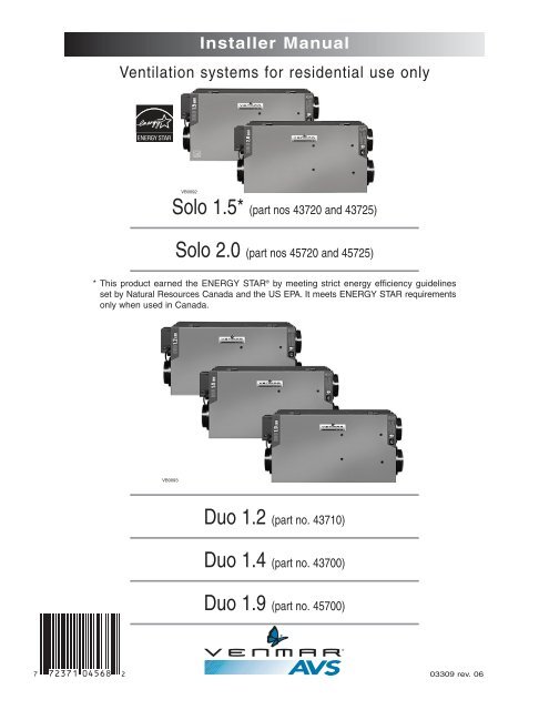
Table of Contents1. REFERENCES........................................................................................32. SERVICE ..............................................................................................42.1 3-D Drawing ..................................................................................................42.2 Parts Ordering Chart ....................................................................................52.3 Technical Support..........................................................................................53. SIZING ................................................................................................64. UNIT TYPE & DEFROST SETTING VS GEOGRAPHICAL LOCATION ................75. TECHNICAL DATA ................................................................................................85.1 Air Distribution (Normal Operation) ..............................................................85.2 Air Distribution (Defrost <strong>and</strong>/or Filtration Mode)............................................85.3 Defrost Cycles Tables ....................................................................................85.4 Dimensions....................................................................................................95.5 Controls <strong>and</strong> Link Options ............................................................................95.6 Specifications ................................................................................................96. TYPICAL INSTALLATIONS........................................................................106.1 Fully Ducted System ..................................................................................106.2 Exhaust Ducted System (Source Point Ventilation) ....................................106.3 Simplified (Volume Ventilation) ....................................................................107. INSTALLATION ................................................................................11-167.1 Locating <strong>and</strong> Mounting the Unit ..................................................................117.2 Planning of the Ductwork ............................................................................117.3 Calculating the Duct Size ............................................................................127.3.1 Example Calculation..........................................................................127.3.2 Example of a Design for a Fully Ducted System ..............................127.4 Installing the Ductwork <strong>and</strong> Registers....................................................13-147.4.1 Fully Ducted System ........................................................................137.4.2 Exhaust Ducted System (Source Point Ventilation) ..........................137.4.3 Simplified Installation (Volume Ventilation)........................................147.5 Connecting the Duct to the Unit ..................................................................157.6 Installing the Exterior Hoods ......................................................................167.7 Connecting the Drain (Solo only) ................................................................168. CONTROL DEVICES ........................................................................17-188.1 Main Controls ..............................................................................................178.2 Optional Controls ........................................................................................178.3 Other Features ............................................................................................182
Table of Contents (cont’d)9. INSTALLATION OF THE CONTROLS ....................................................18-229.1 Dimensions <strong>and</strong> Specifications ................................................................189.2 Installation of the Main Control ............................................................19-219.2.1 Altitude Main Control Installation ........................................................199.2.2 Deco-Touch Main Control Installation ..................................................209.2.3 Venta Main Control Installation ............................................................209.2.4 Main Control Electrical Connection......................................................219.3 Optional Controls Electrical Connection ..................................................219.4 Electrical Connection to the Furnace........................................................229.5 Furnace Interlock Types............................................................................2210. WIRING DIAGRAMS ........................................................................23-2411. AIR FLOW BALANCING ........................................................................2512. OVERALL VERIFICATION........................................................................2611.1 Main Controls............................................................................................2611.2 Optional Controls ......................................................................................2613. MAINTENANCE / INSTRUCTIONS FOR USER ............................................2714. TROUBLESHOOTING........................................................................27-28About this ManualThis manual uses the following symbols to emphasize <strong>part</strong>icular information:! WARNINGIdentifies an instruction which, if not followed, might cause serious personal injuries includingpossibility of death.CAUTIONDenotes an instruction which, if not followed, may severely damage the unit <strong>and</strong>/or its components.NOTE: Indicates supplementary information needed to fully complete an instruction.1. References• HVI, “Installation Manual for Heat Recovery Ventilators”, 1987 edition.• ASHRAE 1984 Systems H<strong>and</strong>book, chapter 11, “Air Distribution Design for Small Heating <strong>and</strong> Cooling Systems”.R 2000<strong>Venmar</strong> QualityAssurance3
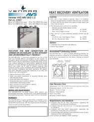
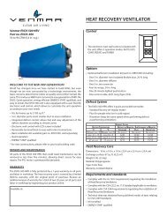
2. Service2.1 3-D DRAWING24232512Unit shown in normal position.41656222621208 10371112191317891816148171543VL0040
2. Service (cont’d)2.2 PARTS ORDERING CHARTNo. Description SOLO 1.5 SOLO 2.0 DUO 1.2 DUO 1.4 DUO 1.9(A) 43720 (A) <strong>45720</strong> 43710 43700 45700(B) 43725 (B) <strong>45725</strong>1 Double Collar Port no. 2 02257 02257 02257 02257 022572 Damper no. 1 (kit) 12454 12454 12454 12454 124543 Damper Rod (kit) 13037 13037 13037 13037 130374 Electronic Board & spacers (kit) 13038 13038 13039 13039 130395 Thermistor (kit) 12895 12895 12895 12895 128956 Door Latches & screws00886 (2) 00886 (2) 00886 (2) 00886 (2) 00886 (2)00601 (4) 00601 (4) 00601 (4) 00601 (4) 00601 (4)7 Damper Actuator Assembly 13734 13734 13734 13734 137348 Basic Filter 03308 03308 03308 03308 033089 Blower Assembly 12908 12912 12909 12909 1291110 Square Damper (kit) 13033 13033 13033 13033 1303311 Top Wheel 02238 02238 02238 02239 0223912 Motor 12109 12157 12109 12109 1215713 Bottom Wheel 02240 02240 02239 02239 0224014 Door Ass’y (including 15 & 16) 13346 13346 13346 13346 1334615 Door Latches (keeper) 00887 (2) 00887 (2) 00887 (2) 00887 (2) 00887 (2)& Screws 00601 (4) 00601 (4) 00601 (4) 00601 (4) 00601 (4)16 Hinge Ass’y (kit) 13036 13036 13036 13036 13036Pleated Optional Filter 03316 03316 03316 03316 0331617 Charcoal Optional Filter 03315 03315 03315 03315 03315Electronic Optional Filter 03314 03314 03314 03314 033141812’’ Cassette (incl. motor) N/A N/A - 15184 -14’’ Cassette (incl. motor) N/A N/A 15185 - 1518519 Recovery Core(A) 03322 (A) 03322(B) 03311 (B) 03311N/A N/A N/A20 Small Basic Filter* 09300 09300 N/A N/A N/A21 Balancing Double Collar Port 02256 02256 02256 02256 0225622 Balancing Damper 02253 02253 02253 02253 0225323 Snap Bushing DP-750 03324 (2) 03324 (2) 03324 (2) 03324 (2) 03324 (2)& O-Ring 03310 (4) 03310 (4) 03310 (4) 03310 (4) 03310 (4)24 Drain Connector (kit) 03203 03203 N/A N/A N/A25 Door Switch (SPST), E69 10A 01825 01825 01825 01825 0182526Media (14’’ Wheel) N/A N/A 15186 - 15186Media (12’’ Wheel) N/A N/A - 15187 -* On Solo units only, if an optinal filter is installed, discard the small basic filter.Please take note that <strong>part</strong>s not listed are not available; those <strong>part</strong>s require assembly knowledge that only manufacturer can guarantee.REPLACEMENT PARTS AND REPAIRIn order to ensure your ventilation unit remains in good working condition, you must use <strong>Venmar</strong> Ventilation Inc. genuinereplacement <strong>part</strong>s only. The <strong>Venmar</strong> Ventilation Inc. genuine replacement <strong>part</strong>s are specially designed for each unit <strong>and</strong>are manufactured to comply with all the applicable certification st<strong>and</strong>ards <strong>and</strong> maintain a high st<strong>and</strong>ard of safety. Anythird <strong>part</strong>y replacement <strong>part</strong> used may cause serious damage <strong>and</strong> drastically reduce the performance level of your unit,which will result in premature failing. Also, <strong>Venmar</strong> Ventilation Inc. recommends to contact a certified service depot forall replacement <strong>part</strong>s <strong>and</strong> repairs.TO ORDER PARTS: Contact your local distributor.2.3 TECHNICAL SUPPORT (FOR ASSISTANCE)For assistance, call on weekdays, 8:30 AM to 5:00 PM (Eastern St<strong>and</strong>ard Time).NOTE: Do not call this number for ordering <strong>part</strong>s.Canada & U.S.A.: 1-800-649-0372 (toll free)5
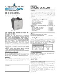
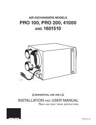
3. SizingThese are the two most common methods used to evaluate the ventilation needs of a house:CSA F326 <strong>and</strong> Canadian Building Code:• High speed: 10 cfm per room20 cfm for the master bedroom <strong>and</strong> the basement• Low speed:40-60% of high speedASHRAE St<strong>and</strong>ard 62-2001:• 0.35 air change per hourRefer to ventilation code of your area to determine which method to use.Example:Second floorMain floorMasterbedroomBathroomno. 1Bathroomno. 2Bedroomno. 2Living roomBathroomno. 3LaundryroomKitchenBedroom no.1Bedroomno. 31320 ft²BasementFamily roomDining room1320 ft²Basement1320 ft²VH0021ACSA F326ASHRAE St<strong>and</strong>ard 62-1989KitchenDining roomLiving roomFamily roomMaster bedroomBedroom no. 1Bedroom no. 2Bedroom no. 3Bathroom no. 1Bathroom no. 2Bathroom no. 3Laundry roomBasement(10 cfm)(10 cfm)(10 cfm)(10 cfm)(20 cfm)(10 cfm)(10 cfm)(10 cfm)(10 cfm)(10 cfm)(10 cfm)(10 cfm)(20 cfm)Volume of basementVolume of main floorVolume of second floorTotal volume10560 ft³10560 ft³10560 ft³31680 ft³x 0.35/h11090 ft³/h÷ 60 (min/h)Total150 cfmTotal185 cfm6
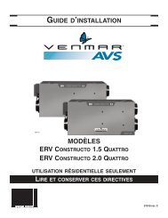
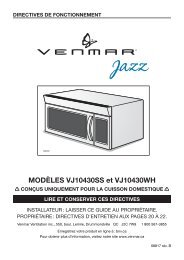
4. Unit Type & Defrost Setting vs Geographical LocationNORTH AMERICAYELLOWKNIFEWHITEHORSEHAY RIVERHORAGEFORT SMITHJUNEAUFORT MCMURRAYZONE APRINCE RUPERT GRANDE PRAIRIEGOOSE BAYEDMONTONPRINCE ALBERTLABRADOR CITYSASKATOONSEPT-ILESCHIBOUGAMAUZONE BCHICOUTIMIGASPÉMATANEBATHURSTQUÉBECCHARLOTTETOWNMONTRÉALST JOST-JOHN HALIFAXVAL-DORNORTH BAYOTTAWATIMMINSSUDBURYTORONTOCALGARYREGINAWINNIPEGLETHBRIDGEHELENABISMARCKSAULT STE MARIEST. PAULMADISONZONE CJASPERKAMLOOPSPENTICTONVICTORIAOLYMPIASALEMBOISERENOSACRAMENTO7DETROITDES MOINESBOSTONSALT LAKE CITYHARTFORDDENVERINDIANAPOLIS HARRISBURGSPRINGFIELDCOLUMBUSTOPEKAWASHINGTONNASHVILLESANTA FERALEIGHOKLAHOMA CITYCOLUMBIAATLANTAPHOENIXSYMPTOM SOLUTION(condensation)ZONE B & C SELECTION CHARTBÂTON ROUGEAUSTINZONE A Solo is recommended. Set :”extended defrost”according to Section 10.Indoor air quality problem DUO<strong>and</strong> / or Excess moisture problem DUO<strong>and</strong>/or Important excess moisture problem SOLOZONE B Solo is recommended but if a Duo unit is used, it has tobe oversized (because of its high humidity transfer efficiency).Set “extended defrost” according to Section 10.VN0001ZONE C Solo or Duo (any models). “Extended defrost” not required(factory defrost strategy pre-set).VQ0013
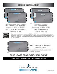
5. Technical Data5.1 AIR DISTRIBUTION (NORMAL OPERATION)STALE AIRTO OUTSIDEFRESH AIRTO BUILDINGSTALE AIRTO OUTSIDESTALE AIRFROM BUILDINGVF0016 SOLO VF0017DUOFRESH AIRFROM OUTSIDESTALE AIRFROM BUILDINGFRESH AIRFROM OUTSIDEFRESH AIRTO BUILDING5.2 AIR DISTRIBUTION (DEFROST AND/OR FILTRATION MODE)FILTERED AIRTO BUILDINGSTALE AIRFROM BUILDINGVF0018SOLOSTALE AIRFROM BUILDINGVF0019DUOFILTERED AIRTO BUILDING5.3 DEFROST CYCLES TABLESSOLO unitsOutside Temperature Defrost Cycles Extended Defrost CyclesCelcius (°C)-5-15-27Fahrenheit (°F)235-17Defrosting (min.)666Operation time (min.)between each defrost cycleDUO unitsOutside Temperature Defrost Cycles Extended Defrost CyclesCelcius (°C)-5-15-27Fahrenheit (°F)235-17Defrosting (min.)999603220Operation time (min.)between each defrost cycle603220Defrosting (min.)101010Defrosting (min.)101010Operation time (min.)between each defrost cycle302015Operation time (min.)between each defrost cycle302015NOTE:THE SOLO AND DUO PERFORMANCE CHARTS ARE LISTED ON THE SPECIFICATION SHEETS OF THESE UNITS.VISIT OUR WEBSITE AT WWW.VENMAR.CA TO ACCESS THOSE DOCUMENTS.8
5. Technical Data (cont’d)5.4 DIMENSIONS6” (152 mm)30¼” (768 mm)171/8” (435 mm)16½”(419 mm)VK0029A5.5 CONTROLS AND LINK OPTIONSMain controls:• Altitude• Deco-Touch• VentaOptional controls:• 20/40/60-minute push-button timer• 60-minute crank timer• DehumidistatLink option:• Furnace interlock(used with forced air systems)5.6 SPECIFICATIONSModel Solo 1.5 Solo 2.0 Duo 1.2 Duo 1.4 Duo 1.9Weight 65 lb (29.5 kg) 67 lb (30.4 kg) 71 lb (32.2 kg) 71 lb (32.2 kg) 73 lb (33.1 kg)Port Diameter 6” (152 mm) 6” (152 mm) 6” (152 mm) 6” (152 mm) 6” (152 mm)Drain Diameter 1/2” (12 mm) 1/2” (12 mm) N/A N/A N/AInstallationChains <strong>and</strong> springs (provided with the unit).Motor SpeedHigh <strong>and</strong> low speed factory set (optional increased or decreased low speed)Electrical supply 120 V, 60 Hz 120 V, 60 Hz 120 V, 60 Hz 120 V, 60 Hz 120 V, 60 HzPower Consumption 150 watts 240 watts 160 watts 160 watts 250 watts9
6. Typical Installations*Installations may vary according to the model number <strong>and</strong> the position (normal or reverse) inwhich the unit is installed.There are three (3) common installation methods.6.1 FULLY DUCTED SYSTEM(Primarily for homes with radiant hot water or electricbaseboard heating. See figure 1.)Moist, stale air is exhausted from the high humidity areas inthe home, such as bathrooms, kitchen <strong>and</strong> laundry room.Fresh air is supplied to bedrooms <strong>and</strong> principal living areas.If required, bathroom fans <strong>and</strong> a range hood may be used tobetter exhaust stale air.Homes with more than one level require at least one exhaustregister at the highest level.VH00026.2 EXHAUST DUCTED SYSTEM (SOURCE POINT VENTILATION)(For homes with forced air heating. See figure 2.)figure 1See 7.4.1for detailsMoist, stale air is exhausted from the high humidity areasin the home, such as bathrooms, kitchen <strong>and</strong> laundryroom. Fresh air is supplied to the cold air return or thesupply duct of the furnace. If required, bathroom fans <strong>and</strong>a range hood may be used to better exhaust stale air.Homes with more than one level require at least oneexhaust register at the highest level.NOTE: For this type of installation, it is not essentialthat the furnace blower runs when the unit isin operation, but we recommend it.VH0006figure 2See 7.4.2for details6.3 SIMPLIFIED (VOLUME VENTILATION)(For homes with forced air heating. See figure 3.)Fresh air <strong>and</strong> exhaust air flow through the furnace ductswhich simplifies the installation.The use of bathroom fans <strong>and</strong> a range hood is suggested toexhaust stale air.NOTE:For this type of installation, the furnace blowershould be running when the unit is in operation.VH0007figure 3See 7.4.3for details10
7. Installation! WARNINGWhen applicable local regulation comprises more restrictive installation <strong>and</strong>/or certificationrequirements, the aforementioned requirements prevail on those of this document <strong>and</strong> theinstaller agrees to conform to these at his own expenses.! WARNINGWhen performing installation, servicing or cleaning the unit, it is recommended to wear safetyglasses <strong>and</strong> gloves.INSPECT THE CONTENTS OF THE BOX• Inspect the exterior of the unit for shipping damage. Ensure that there is no damage to the door, door latches,door hinges, dampers, duct collars, cabinet, etc.• Inspect the interior of the unit for damage. Ensure that the fan motor assembly, recovery module, insulation,dampers, damper actuator <strong>and</strong> condensation tray (Solo) are all intact.• If the unit was damaged during shipping, contact your local distributor. (Claim must be made within 24 hours afterdelivery.)• Use checklist included with the unit to ensure that no <strong>part</strong>s are missing.7.1 LOCATING AND MOUNTING THE UNITNOTE: Please note that the unit can be installed in either the “normal” or “reverse” (upside down) position.Choose an appropriate location for the unit:• Within an area of the house where the temperature is kept above 10°C / 50°F<strong>and</strong> below 40°C/104°F.• Away from living areas (dining room, living room, bedroom), if possible.• So as to provide easy access to the interior cabinet for every three months <strong>and</strong>annual maintenance, <strong>and</strong> to the control panel on the side of the unit.• Close to an exterior wall, so as to limit the length of the insulated flexible duct to<strong>and</strong> from the unit.• Close to a drain. If no drain is close by, use a pail to collect run-off.VD0037(Solo models only.)figure 4• Away from hot chimneys, electrical panel <strong>and</strong> other fire hazards.• Allow for a power source (st<strong>and</strong>ard outlet).Hang the unit with the 4 chains <strong>and</strong> springs provided (see figures 4 <strong>and</strong> 5).VD0038figure 5CAUTIONMake sure the unit is level, with a 1/8’’ (3 mm) tilt backwards (seefigure 6).1/8”(3 mm)7.2 PLANNING OF THE DUCTWORKVD0039Afigure 6a) Follow the instructions in Section 6.3 next page to determine the appropriate duct diameters for your system.b) Keep it simple. Plan for a minimum number of bends <strong>and</strong> joints. Keep the length of insulated duct to a minimum.c) Do not use wall cavities as ducts. Do not use branch lines smaller than 4” Ø (102 mm Ø).d) Do not ventilate crawl spaces or cold rooms. Do not attempt to recover the exhaust air from a dryer or a rangehood. This would cause clogging of the recovery module. Use sheet metal for the kitchen exhaust duct.e) Be sure to plan for at least one exhaust register on the highest lived-in level of the house if it has 2 floors or more.11
7. Installation (cont’d)7.3 CALCULATING THE DUCT SIZEUse the table below to ensure that the ducts you intend to install will be carrying air flows at or under therecommended values. Avoid installing ducts that will have to carry air flows near the maximum values <strong>and</strong>never install a duct if its air flow exceeds the maximum value.DuctDiameterRecommended Air Flow Maximum Air Flow4” (102 mm) 40 cfm 19 l/s 68 m³/h 60 cfm 28 l/s 102 m³/h5” (127 mm) 75 cfm 35 l/s 127 m³/h 110 cfm 52 l/s 187 m³/h6” (152 mm) 120 cfm 57 l/s 204 m³/h 180 cfm 85 l/s 306 m³/h7” (178 mm) 185 cfm 87 l/s 314 m³/h 270 cfm 127 l/s 459 m³/h8” (203 mm) 260 cfm 123 l/s 442 m³/h 380 cfm 179 l/s 645 m³/hENDBRANCHES5”Ø70 CFMMAIN BRANCH6”Ø 140 CFMNOTE: Examples 7.3.1 <strong>and</strong> 7.3.2 use imperial measures.figure 7The same calculation applies to metric measures.7.3.1 Example of calculation:Problem: My installation requires two exhaust registers (one for the kitchen, one for the bathroom). I willconnect these registers to a main duct which will connect to the unit (high speed performance value of140 cfm). What size of duct should I use for the main exhaust duct <strong>and</strong> for the two end branches leadingto the registers? (See figure 7.)Solution: Simplified method. (For a more detailed method of calculating duct size refer to the ASHRAE orHRAI HANDBOOK).Main duct: Table above indicates a 6” Ø duct: Recommended air flow: 120 cfm; maximum air flow: 180 cfm.The high speed air flow of 140 cfm is close enough to the recommended value (120) <strong>and</strong> far enough awayfrom the maximum value (180). Therefore a 6” Ø duct or larger is an appropriate choice for the main exhaustduct.End branches: Each end branch will have to transport an air flow of 70 cfm (140 divided by 2). Table aboveindicates a 5” Ø duct: Recommended air flow: 75 cfm; maximum air flow: 110 cfm. The high speed air flowof 70 cfm is close enough to the recommended value (75) <strong>and</strong> far enough away from the maximumvalue (110). Therefore a 5” Ø duct or larger is an appropriate choice for the 2 end branches.NOTE: A 4” Ø duct would have been too small because the maximum acceptable value for a 4” Øduct is 60 cfm.VI00037.3.2 Example of a design for a fully ducted system for a unit having a high speed performanceof 222 cfm (see figure 8).5”5” Ø65 cfm6” Ø129 cfm6” Ø93 cfmVI00045” Ø64 cfm6”7” Ø 222 cfm4”4”4” Ø42 cfm6”4”7” 7”figure 84” Ø 42 cfm4”6” Ø 84 cfm7” Ø 222 cfm6”6” Ø 96 cfm6”6” Ø 138 cfm12
7. Installation (cont’d)7.4 INSTALLING THE DUCTWORK AND REGISTERS! WARNINGNever install a stale air exhaust register in a room where there is a combustion device, such as agas furnace, a gas water heater or a fireplace.CAUTIONThe ductwork is intended to be installed in compliance with all local <strong>and</strong> national codes that are applicable.7.4.1 Fully Ducted System (as illustrated in Section 6.1)Stale air exhaust ductwork:• Install registers in areas where contaminants are produced: Kitchen, bathrooms, laundry room, etc.• Install registers 6 to 12 inches (152 to 305 mm) from the ceiling on an interior wall OR install them inthe ceiling.• Install the kitchen register at least 4 feet (1.2 m) from the range.• If possible, measure the velocity of the air flowing through the registers. If the velocity is higherthan 400 ft/min. (122 m/min), then the register type is too small. Replace with a larger one.Fresh air distribution ductwork:• Install registers in bedrooms, dining room, living room <strong>and</strong> basement.• Install registers either in the ceiling or high on the walls with air flow directed towards the ceiling.(The cooler air will then cross the upper <strong>part</strong> of the room, <strong>and</strong> mix with room air before descending tooccupant level.)• If a register must be floor installed, direct the air flow up the wall.7.4.2 Exhaust Ducted System (Source Point Ventilation) (as illustrated in Section 6.2)Stale air exhaust ductwork: (same as for Fully Ducted System, described on point 7.4.1)Fresh air distribution:! WARNINGWhen performing duct connection to the furnace, installation must be done in accordance withall applicable codes <strong>and</strong> st<strong>and</strong>ards. Please refer to your local building code.CAUTIONWhen performing duct connection to the furnace supply duct, this duct must be sized to support theadditional airflow produced by the ERV/HRV. Also, use a metal duct. It is recommended that theERV/HRV is running when the furnace is in operation in order to prevent backdrafting inside ERV/HRV.There are two methods for connecting the unit to the furnace:Method 1: Supply side connection• Cut an opening into the furnace supply duct at least18 inches (0.5 m) from the furnace.• Connect this opening to the fresh air distribution port of theHRV/ERV (use metal duct, see figure 9).• Make sure that the HRV/ERV duct forms an elbow inside thefurnace ductwork.• If desired, interlock (synchronize) the furnace blower operationwith the HRV/ERV operation. (See Section 9.3).Metal ductMinimum18” (0.5 m)Method 2: Return side connection• Cut an opening into the furnace return duct not less than10 feet (3.1m) from the furnace (A+B).• Connect this opening to the fresh air distribution port of theHRV/ERV (see figure 10).NOTE: For Method 2, it is not essential that the furnaceblower runs when the unit is in operation, but werecommend it. If desired, synchronize the furnaceblower operation with the HRV/ERV operation.(See Section 9.3).13VD0172VD0108figure 9AA+B = not lessthan 10’ (3.1 m)figure 10B
7. Installation (cont’d)7.4 INSTALLING THE DUCTWORK AND REGISTERS (CONT’D)7.4.3 Simplified installation (Volume Ventilation) (as illustrated in Section 6.3)! WARNINGWhen performing duct connection to the furnace, installation must be done in accordance withall applicable codes <strong>and</strong> st<strong>and</strong>ards. Please refer to your local building code.CAUTIONWhen performing duct connection to the furnace ducts (Method 1), these ducts must be sized tosupport the additional airflow produced by the ERV/HRV. Also, the supply duct must be a metalduct. It is recommended that the ERV/HRV is running when the furnace is in operation in order toprevent backdrafting inside ERV/HRV.There are two methods (figures 11 <strong>and</strong> 12) for connecting the unit to the furnace:Method 1: return-supplyMethod 2: return-returnMetal ductMinimum 18”(0.5 m)AABVD0171A+B = not lessthan 10’ (3.1 m)Bfigure 11figure 12Stale air intake:• Cut an opening into the furnace return duct (not less than 10 feet (3.1 m) from the furnace).• Connect this opening to the stale air intake port on the HRV/ERV as shown.VD0111Minimum 3’(0.9 m)A+B = not lessthan 10’ (3.1 m)Fresh air distribution: (same instructions as for Method 1 or Method 2, Section 7.4.2).CAUTIONIf using Method 2, make sure the furnace blower operation is synchronized with the unit operation!See Section 9.3.For Method 2 (return-return) make sure there is a distance of at least 3 feet (0.9 m) between the2 connections to the furnace.NOTE: For Method 1, it is not essential to synchronize the furnace blower operation with the unit operation,but we recommend it.14
7. Installation (cont’d)7.5 CONNECTING THE DUCTS TO THE UNITInsulated flexible ductUse the following procedure for connecting the insulated flexible duct to the ports on the unit (exhaust to outside <strong>and</strong>fresh air from outside).a) Pull back the insulation to expose the flexible duct.b) Connect the interior flexible duct to the port using a duct tie.c) Carefully seal the connection with duct tape.d) Pull the insulation over the joint <strong>and</strong> tuck it between the inner <strong>and</strong> outer rings of the double collar.e) Pull the vapor barrier over the insulation <strong>and</strong> over the outer ring of the double collar.f) Apply duct tape to the joint making an airtight seal. Avoid compressing the insulation when you pull the tape tightlyaround the joint. Compressed insulation loses its R value <strong>and</strong> causes water dripping due to condensation on theexterior surface of the duct.CAUTIONMake sure that the vapor barrier on the insulated ducts does not tear during installation to avoidcondensation within the duct.a) b) c) d), e) f)VJ0001VJ0002VJ0003 VJ0004 VJ0005Rigid ductUse duct tape to connect the rigid ducts to the ports.CAUTIONDo not use screws to connect rigid ducts to the ports.Make sure that the 2 balancing dampers are left in a fully open position before connecting the ducts to these ports(fresh air distribution port <strong>and</strong> stale air exhaust port as shown on figure 13).VJ0007figure 1315
7. Installation (cont’d)7.6 INSTALLING THE EXTERIOR HOODSChoose an appropriate location for installing the exteriorhoods:• at a minimum distance of 6 feet (1.8 m) between thehoods to avoid cross-contamination• at a minimum distance of 18 inches (457 mm) from theground! WARNINGMake sure the intake hood is at least 6 feet (1.8 m)away from any of the following:• Dryer exhaust, high efficiency furnace vent,central vacuum vent• Gas meter exhaust, gas barbecue-grill• Any exhaust from a combustion source• Garbage bin <strong>and</strong> any other source of contaminationRefer to figure 14 for connecting the insulated duct to thehoods. Place the “FRESH AIR INTAKE” sticker, provided inthe installation kit, on corresponding hood. An “Anti-GustIntake Hood” should be installed in regions where a lot ofsnow is expected to fall.EXHAUSTHOOD18”(457 MM)OPTIONAL DUCTTAPE AND DUCT TIE LOCATIONCAULKINGINTAKEHOOD6” Ø(152 MM)6’18”(1.8 M) (457 MM)6’(1.8 M)18”(457 MM)7.7 CONNECTING THE DRAIN (SOLO ONLY)VD0028figure 14Inside view± 12"(± 305 mm)± 12"(± 305 mm)VO0010To install the drain fittings, punchthe 2 knock-out sections located atthe bottom of the unit.VO00081 2In order to keep the drain pan intact,h<strong>and</strong> tighten the 2 plastic drain fittingsto the unit using the gaskets, washers<strong>and</strong> nuts as shown.VO0005A3Cut 2 sections of plastic tubing,about 12” (305 mm) long <strong>and</strong> attachthem to each drain fitting. Join the 2short sections to the “T” junction<strong>and</strong> main tube as shown.TIE-WRAPVO0011TO DRAINMake a water trap loop in the tube toprevent the unit from drawing unpleasantodors from the drain source. Make surethis loop is situated BELOW the “T” asshown. This will prevent water frombeing drawn back up into the unit incase of negative pressure. Run the tubeto the floor drain or to an alternativedrain pipe or pail. Be sure there is aslight slope for the run-off.4 VD0231A± 1”If using a pail to collect water, locatethe tube end approximately 1” fromthe top of the pail in order to preventwater from being drawn back upinto the unit.16Inside viewVO00125 6From the inside, install 2 snap bushingson top of the unit. Do not punchthe 2 knock-out sections.
8. Control Devices8.1 MAIN CONTROLSALTITUDE modelDECO-TOUCH modelVENTA modelMODEPREFSETSMARTVC0101VC0117VENTAVC0010MODELS ALTITUDE DECO-TOUCH VENTADETECTORINDICATORS TYPESMODESSWITCHESOff Position X X XIntermittent exchange OR OFF (ON - OFF or ON - Recirculation) X XLow speed continuous exchange X X XHigh speed continuous exchange X X XRecirculation (manual mode performing air recirculation inside the house) X XProgram (programs the desired ventilation according to the period of the day) XSMART (entirely automatic mode optimizing ventilation)XIndoor TemperatureXOutdoor TemperatureXIndoor Relative HumidityXMode indicator X XUnit statusXSpeed indicator X XMaintenance indicator X XDay <strong>and</strong> Hour indicatorsXSliding buttonXPush-button X X8.2 OPTIONAL CONTROLS20/40/60-MINUTE PUSH-BUTTON TIMER:This remote illuminated switch is typically installed in bathrooms, kitchen <strong>and</strong> laundry room to provide 20, 40 or 60 minutesof high speed ventilation at the push of a button.60-MINUTE CRANK TIMER:This timer allows up to 60 minutes of high speed operation to be selected from a remote location.DEHUMIDISTAT:This optional control helps control maximum humidity level during fall, winter <strong>and</strong> spring.You will find a relative humidity % scale meant to reduce the window condensation problems.17
8. Control Devices (cont’d)8.3 OTHER FEATURESFURNACE INTERLOCK (FOR FORCED AIR HEATING SYSTEM)The furnace can be interlocked so that it will run simultaneously with the ERV or HRV to ensure proper distribution offresh air throughout the house.PERMANENT MEMORYOur Altitude <strong>and</strong> Deco-Touch controls have a default memory feature in the event of a power outage. Even the date ofthe last service reminder is maintained as a convenience to the homeowner.NOTE: If the power failure duration is more than 4 hours, the day <strong>and</strong> hour settings must be reprogrammed (onAltitude control only).CONTROL UPGRADESAll controls can be used on any unit, so a Venta control can be upgraded to a Deco-touch or Altitude in the future.9. Installation of the Controls9.1 DIMENSIONS AND SPECIFICATIONS (MAIN CONTROLS)VOLTAGE:ALTITUDE12 volts DCVOLTAGE:DECO-TOUCH12 volts DC4¼" (107 mm)1"(26 mm)2¾" (70 mm)4½" (114 mm)4" (102 mm)VC0105AFRONT VIEWSIDE VIEWVC0118AVOLTAGE:5" (127 mm)VENTA12 volts DC1³/8"(35 mm)5" (127 mm)VC0016AFRONT VIEWSIDE VIEW18
9. Installation of the Controls (cont’d)9.2 INSTALLATION OF THE MAIN CONTROL! WARNINGAlways disconnect the unit before making any connections. Failure in disconnecting power couldresult in electric shock or damage of the wall control or electronic module inside the unit.CAUTIONFailure to comply with the following can cause erratic operation of the unit:• Never install more than one main wall control per unit.• Keep control low voltage wiring at least 1 foot (305 mm) away from motors, lighting ballast,light dimming circuit <strong>and</strong> power distribution panel. Do not route control wiring alongside housepower wiring.• Ensure the wires are securely connected.9.2.1 Altitude Main Control Installation1. Route the cable from the unit to a convenient locationfor the wall control.2. Detach the front modulefrom the mounting plateby pulling the bottom <strong>part</strong>.3. Run the cable (4 wires)through the central openingof the mounting plate <strong>and</strong>mount this plate to thewall using screws (notincluded). If needed, usewall anchors (not included).VC0102VC01034. Splice back the end of thecable to access the 4wires. Strip the end ofeach wire. Connect eachwire to its correspondingterminal on the back of thefront module: YELLOWwire to “Y”, RED wire to“R”, GREEN wire to “G”<strong>and</strong> BLACK wire to “B”.REDWIREGREENWIREVE01735. Reinstall the front module over the back plate.YELLOWWIREBLACKWIRECAUTIONBe careful not to pinch wires when reinstallingthe front module on its back plate.9.2.2 Deco-Touch Main Control Installation1. Cut a 2 7 /8” x 1 ³/8” hole inwall at a convenientlocation for the wall control.Route the cable from theunit to this hole.NOTE: Dimensions shownare for an installationwithout wall box.4. Strip the end of the cableto access the 4 wires. Stripthe end of each wire. Usinga small flat blade screwdriver,connect each wire to itscorresponding terminal onthe back of the wallcontrol: YELLOW wire to“Y”, RED wire to “R”,GREEN wire to “G” <strong>and</strong>BLACK wire to “B”.YRGBVE02432. Temporarily place theswitch over the hole <strong>and</strong>mark both mountingscrew hole positions.3. Remove the switch, drillboth screw holes (Ø 3/16”)in wall <strong>and</strong> insert wallanchors (included).VC0116AØ 3/16”, typ.5. Mount the wall control tothe wall.VC011519
9. Installation of the Controls (cont’d)9.2 INSTALLATION OF THE MAIN CONTROL (CONT’D)9.2.3 Venta Main Control Installation1. Route the cable from the unit to the location of the control. The Venta wall control must be installed in a centrallocation on the main floor. Typical locations for this control are kitchen, main hallways <strong>and</strong> family room.2. Remove the buttons <strong>and</strong> the cover plate of the control.VC01062"(5 cm)3. Install the wall control 60 inches (1.5 m) from the floor <strong>and</strong> leave afree space of at least 2 inches (5 cm) to the right of the control toallow user to slide out the control instructions.Use the template provided in the control box to position the wirehole <strong>and</strong> the screw holes. Use the screws <strong>and</strong> the plastic anchorsprovided in the installation kit to secure the control.60" (1.5 m)4. Connect the wires to the main control.Y R GBVE01245. Make sure the instruction pull-out is in the occupant’s language. If not, turn it tothe other side.VC00616. Re-install the cover plate <strong>and</strong> the buttons.20
9. Installation of the Controls (cont’d)9.2 INSTALLATION OF THE MAIN CONTROL (CONT’D)9.2.4 Main Control Electrical Connection1. Connect the wires to their corresponding position inside the electricalcom<strong>part</strong>ment. Make sure the connections of the unit <strong>and</strong> of the wall controlcorrespond exactly.VE0084F F I OCOL YRG B2. Connect the optional controls (if applicable) by referring to section 9.3.3. Do the appropriate connection to the furnace (if applicable) by referring to Section 9.4.4. NOTE:If you are in a cold region (zone A or B, as defined in Section 4), set up “extended defrost” by removing jumperJU1F on the main circuit board inside the electrical com<strong>part</strong>ment (see Section 10).5. Plug in the unit <strong>and</strong> do the “overall verification” of the system as described in Section 12.9.3 OPTIONAL CONTROLS ELECTRICAL CONNECTIONMAIN PC BOARDOLOCIJ3987654321J11 4 72 5 83 6 90L 0C IVE0176ADEHUMIDISTAT orCRANK TIMERPUSH-BUTTON SWITCHESREAR VIEW21
9. Installation of the Controls (cont’d)9.4 ELECTRICAL CONNECTION TO THE FURNACE! WARNINGNever connect a 120-volt AC circuit to the terminals of the furnace interlock (st<strong>and</strong>ard wiring).Only use the low voltage class 2 circuit of the furnace blower control.For a furnace connected to cooling system:On some older thermostats, energizing the “R” <strong>and</strong> “G” terminals at the furnace has the effect of energizing “Y” at thethermostat <strong>and</strong> thereby turning on the cooling system. If you identify this type of thermostat, you must use the“alternate furnace interlock wiring”. An additional control relay will then have to be installed.St<strong>and</strong>ard furnace interlock wiringAlternate furnace interlock wiringFOURWIRESTWO WIRESheating onlyWRGCYFURNACE24-VOLTTERMINAL BLOCKVE0010AW R G YTHERMOSTATTERMINALSUNIT CONTROL CONNECTORJ3TWO WIRES987654321F FI OC OL Y R G BCOOLING SYSTEM4 WIRES2 WIRES(heating only)WRGCYW R G YTHERMOSTATTERMINALwiringnutsREDGREENBLUENCNOCOM*FURNACE INTERLOCKRELAYUnit Control Module9-PIN AMP PLUGJ1123456789GRAYBROWNFURNACE24-VOLTTERMINAL BLOCK2 WIRESCOOLING SYSTEMVE0009A *FURNACE INTERLOCK RELAY, PART NO. 126589.5 FURNACE INTERLOCK TYPESThe new TII (Timed Intermittent Interlock) function consists in 2 modes: the st<strong>and</strong>ard mode <strong>and</strong> the special mode.Therefore, the electronic board terminal of the Solo <strong>and</strong> Duo units has now 2 additional jumpers intalled across C <strong>and</strong>D terminals.STANDARD MODEThe st<strong>and</strong>ard mode is the default mode (the interlock function stay as it was). On st<strong>and</strong>ard mode, the jumper positionson terminal C <strong>and</strong> D keep them non-active:SOLO UNITSDUO UNITSVE0125A B C D E F G A B C D E F GSPECIAL MODEThe special mode drives the furnace interlock relay independently than the HRV/ERV operation. The K4 relay isactivated for 10 minutes, <strong>and</strong> then is deactivated for a 20-minute period, no matter the HRV/ERV comm<strong>and</strong>, even ifthe HRV/ERV is stopped. To perform the special mode, unplug the unit <strong>and</strong> change the jumper locations as shownbelow:SOLO UNITSDUO UNITSVE0126A B C D E F G A B C D E F GNOTE: For both Solo <strong>and</strong> Duo units, C <strong>and</strong> D terminals are now activated.22
A110. Wiring Diagrams! WARNINGRisk of electric shocks. Before performing any maintenance or servicing, always disconnect theunit from its power source. This product employs overload protection (fuse). A blown fuse indicatesan overload or short-circuit situation. If the fuse blows, unplug the product from the outlet.Replace the fuse as per the servicing instructions (follow product marking for proper fuse rating)<strong>and</strong> check the product. If the replacement fuse blows, a short-circuit may be present <strong>and</strong> the productshould be discarded or returned to an authorized service facility for examination <strong>and</strong>/or repair.ConnectionModels: SOLO 1.5 <strong>and</strong> 2.0NEUTRALJ1 2120V 60HzBKGRYRBKFROM MAINNOTES 1, 5S1LogicWALL CONTROLWALL CONTROLWALL CONTROLWALL CONTROLM1J1 1FANMOTORMEDNCHIGHLOWJ1 6NOTE 5OPTIONALOVERRIDE SWITCHOVERRIDE SWITCHOVERRIDE LEDYJ1 3J1 4NOTES 5, 6OPTIONALFURNACE BLOWERINTERLOCKCOLOR CODEBK BLACK NC NO CONNECTIONBL BLUE O ORANGEBN BROWN R REDG GREEN W WHITEGY GREY Y YELLOWM2K2RELAYK1RELAYJ1 9NOTE 4J1 8DAMPERMOTORK5RELAYA1J3 1FURNACE BLOWER INTERLOCKCLASS 2 CIRCUIT ONLYK4RELAYJ3 2ELECTRONIC ASSEMBLYJU121ABCDEFG4 5 6 7 8 9DEFROSTTEMPERATURESENSORJ4VE0018AFF IOCOLY RGB1 2 3R1M1NEUTRALHIGHLOWMEDIUMFAN MOTORT1X1GYOGRBLJ3GY 12OG3NCBNC1BNGYJU 1DEFROST TIMEJUMPERS TABLE MO 21DEFROST/VENTILATIONA B C D E F GTYPE MINUTES23°F 5°F -22°FJU1A JU1B JU1C JU1D JU1E JU1F JU1G -5°C -15°C -27°CIN OUT OUT OUT IN IN OUTSTANDARD MODE43720, <strong>45720</strong>,43725, <strong>45725</strong>6/60 6/32 6/20IN OUT OUT OUT IN OUT OUTEXTENDED DEFROSTSTANDARD MODE10/30 10/20 10/15OUT IN IN IN IN IN OUTSPECIAL MODE43720, <strong>45720</strong>,43725, <strong>45725</strong>6/60 6/32 6/20OUT IN IN IN IN OUT OUTEXTENDED DEFROSTSPECIAL MODE10/30 10/20 10/15. .RR(NOTE 2)741J12BL3BL96X2 M2OBKWELECTRONIC ASSEMBLYBLBLG DAMPER MOTOR12BLBL233GGLINE VOLTAGEMAIN EARTHINGPOINTLOW VOLTAGE ANDFIELD WIREW1GW120VNOCOMBKNEUTRALLINE F1NOTE 7BKFUNCTION TABLE RELAYMODE K1 K2 K4* K5Intermittent 0 0 0 1Exchange Low 1 0 1 0Exchange High 1 1 1 0Circulation Low 1 0 1 1Circulation High 1 1 1 1Defrost Cycle 1 1 1 1Off 0 0 0 1NEMA-15P5-15 PLUGDOOR INTERLOCKSWITCH S1VE0017ANOTES1- Controls available. See Section 8.0 (Low voltage only, 12VDC)2- The factory set wiring for blower speed selection is high <strong>and</strong> low. Medium speedcan be selected instead of low speed. Disconnect the RED wire from the motorRED tap <strong>and</strong> connect it to the motor BLUE tap.3- If any of the original wire, as supplied, must be replaced, use the same orequivalent wire.0 = Relay coil is de-energized1 = Relay coil is energized* On special mode, K4 is cycling 10 min. ON <strong>and</strong> 20 min. OFF4- Use the factory supplied protective tubing.5- The field wiring must comply with applicable codes, ordinances <strong>and</strong> regulations.6- The furnace fan circuit must be class 2 circuit only.7- SPECIFIED UL LISTED/CSA CERTIFIED LINE FUSE.LittelFuse (225 003), 2AG Fast-Acting Fuse. 224/225 Series, Rating: 3A.
123411234123123WARNER ELECTRIC23Models: DUO 1.2, 1.4 <strong>and</strong> 1.9BK410. Wiring Diagrams (cont’d)! WARNINGRisk of electric shocks. Before performing any maintenance or servicing, always disconnect theunit from its power source. This product employs overload protection (fuse). A blown fuse indicatesan overload or short-circuit situation. If the fuse blows, unplug the product from the outlet.Replace the fuse as per the servicing instructions (follow product marking for proper fuse rating)<strong>and</strong> check the product. If the replacement fuse blows, a short-circuit may be present <strong>and</strong> the productshould be discarded or returned to an authorized service facility for examination <strong>and</strong>/or repair.ConnectionNEUTRALJ1 2120V 60HzFROM MAINWALL CONTROLWALL CONTROL NOTE 5WALL CONTROLWALL CONTROLOVERRIDE SWITCHOVERRIDE SWITCH NOTE 5OVERRIDE LED OPTIONALFURNACE BLOWER NOTE 6INTERLOCK OPTIONALGRYS1LogicA1RBKYM1LOWFANMOTORNCHIGHMEDIUMJ1 6THERMAL WHEELASSEMBLYJ1 1J1 3J1 4 J9 1M3K2RELAYK1RELAYX3NOTE 4G GROUNDW NEUTRALR LINEBK CAPACITORDRIVING MOTORRT1GRT1YA121J1 8BYPASSTHERMAL ACTUATORSEE BOXES BELOWR2 C2VBNVVBYPASS THERMAL ACTUATORABCDEFGOLY R G B4 5 6 7 8 9DEFROSTTEMPERATURESENSORM3JU1J2 1 DRIVINGMOTORK5 RELAYJ1 7J2 3J2 2J4F F I1 2 3R1J1 5M2K3RELAYDAMPERMOTORM1FAN MOTORNEUTRALHIGHBNLOWMEDIUMBNYT12 3GYOGRBLX1GYOG NCBNJ31J2J3 1BNGYFURNACE BLOWER INTERLOCKCLASS 2 CIRCUIT ONLYK4RELAYC1RR74J3 2ELECTRONIC ASSEMBLY1X2 M2J12VE0020ABKV3Y96YOGBLBLGBKWBLELECTRONIC ASSEMBLYJU 12JUMPERS TABLE 1MODELA B C D E F GDAMPER MOTOR. .JU1A JU1B JU1C JU1D JU1E JU1F JU1GIN IN OUT OUT IN IN OUT STANDARD MODE 43700, 45700, 43710IN IN OUT OUT IN OUT OUT STANDARD MODE EXTENDED DEFROSTIN IN IN IN IN IN OUT SPECIAL MODE 43700, 45700, 43710MAIN EARTHINGPOINTGW1NEUTRALWCOM NOF1120V 60 HzLINEBKBKDOOR INTERLOCK NOTE 7NEMA-15PSWITCH S15-15 PLUGM3X3M3G GROUNDG GROUNDW NEUTRALW NEUTRALR LINER LINEBK CAPACITORCAPACITORR2/R3BKC2R2 C2DRIVING MOTORDRIVING MOTORRT1RT1VVLINE VOLTAGELOW VOLTAGE ANDFIELD WIRE24X3IN IN IN IN IN OUT OUT SPECIAL MODE EXTENDED DEFROSTVBYPASS THERMAL ACTUATORVBYPASS THERMAL ACTUATORBODINE OR EASTERN AIR DEVICESFUNCTION TABLE RELAY DEFROSTMODE K1 & K4* K2 K3 K5Intermittent 0 0 0 0Continuous Low 1 0 1 0Continuous High 1 1 1 0 K5 active only (-15°C
11. Air Flow BalancingWHAT YOU NEED TO BALANCE THE UNIT• A magnehelic gauge capable of measuring 0 to 0.5 inch of water(0 to 125 Pa) <strong>and</strong> 2 plastic tubes.• The balancing chart provided with the unit.PRELIMINARY STAGES TO BALANCE THE UNIT• Seal all the unit ductwork with tape. Close all windows <strong>and</strong> doors.• Turn off all exhaust devices such as range hood, dryer <strong>and</strong> bathroomfans.• Make sure the balancing dampers are fully open.• Make sure all filters are clean (if it is not the first time you balance theunit).BALANCING PROCEDURE1. Set the unit to high speed:Make sure that the furnace blower is ON if the installation is in any wayconnected to the ductwork of the cold air return. If not, leave furnace blowerOFF. If the outside temperature is below 0°C / 32°F, make sure the unit isnot running in defrost while balancing. (By waiting 10 minutes afterplugging the unit in, you are assured that the unit is not in a defrost cycle.)Disconnect the wire of the bypass damper (Duo only).2. Place the magnehelic gauge on a level surface <strong>and</strong> adjust it to zero.3. Connect tubing from gauge to EXHAUST air flow pressure taps (see diagram).Be sure to connect the tubes to their appropriate high/low fittings. If thegauge drops below zero, reverse the tubing connections.NOTE: It is suggested to start with the exhaust air flow readingbecause the exhaust has typically more restriction than thefresh air, especially in cases of fully ducted installations orsource point ventilation. Place the magnehelic gaugeupright <strong>and</strong> level. Record equivalent AIR FLOW of thereading according to the balancing chart.4. Move tubing to FRESH air flow pressure taps (see diagram). Adjust thefresh air balancing damper until the fresh air flow is approximately thesame as the EXHAUST air flow. If fresh air flow is less than exhaust airflow, then go back <strong>and</strong> adjust the exhaust balancing damper to equal thefresh air flow.5. Secure both dampers in place with tape or with a fastening screw.VP0009VD0051SOLOVP0010DUOVP0011Fresh air flowExhaust air flowExhaust air flowFresh air flow6. Write the required air flow information on a label <strong>and</strong> stick it near the unitfor future reference (date, maximum speed air flows, your name, phonenumber <strong>and</strong> business address). Connect the wire of the bypassdamper (Duo only).VE0021NOTE:Always unplug bypass wire whilebalancing a Duo.NOTE:The unit is considered balanced even if there is a difference of± 10 cfm or ± 5 l/s or 17 m³/h between the two air flows.VD005225
12. Overall Verification12.1 MAIN CONTROLSThis procedure allows the installer to verify that all modes of operation are fully functional.During the verification of a main control, make sure that all optional remote controls are inactive.ALTITUDEDECO-TOUCHAt its very start-up, theAltitude wall control willperform a bootingsequence before beingready to operate. The bootingsequence is donewhen the hour display isflashing.Refer to the installation sheetincluded with the Deco-Touch wallcontrol.Refer to the installationVC0101sheet included with theAltitude wall control for more details in programming <strong>and</strong>setting preferences.MODEPREFSETSMARTVC0117VENTA (6 different control scenarios to be tested)Set the slider Set dehumidistat Results expectedswitch to dial to fan speed / damper1 OFF maximum counterclockwise motor off / closed2 OFF maximum clockwise motor off / closed3 MIN. maximum counterclockwise low speed / open4 MIN. maximum clockwise high speed / open5 MAX. maximum counterclockwise high speed / open6 MAX. maximum clockwise high speed / openVENTAVC001012.2 OPTIONAL CONTROLSFirst, turn OFF the main control device before checking the remote optional controls.20/40/60-MINUTE PUSH-BUTTON TIMER:Activate the push-button. Within2 seconds, push one time for20 minutes, two times for40 minutes or three times for a60-minute activation.20 min.40 min.DEHUMIDISTAT:Turn dial to the maximumclockwise position (20%).Result expected:Motor speed changes to high.60 min.Results expected:1. Motor speed: High for 20, 40or 60 minutes.2. Indicator light goes “ON” <strong>and</strong>VC0007flashes every 5 seconds (onetime to indicate a 20-minute operation, two timesfor a 40-minute, <strong>and</strong> three times for a60-minute operation).NOTE: To stop activation, push one more time.60-MINUTE CRANK TIMER:Activate the timer.Results expected:Motor speed: High for up to60 minutes.VC0009OFFTurnHOLDPast106020504030MINUTESVC001726
13. Maintenance / Instructions for User! WARNINGRisk of electric shocks. Before performing any maintenance or servicing, always disconnect theunit from its power source.• Review with the user the steps required for the regular maintenance of her/his ventilation system. These steps aredescribed in detail in the user manual:FOUR TIMES A YEAR:• Inspect the intake hood, <strong>and</strong> clean if needed.• Clean the filters.• Clean the interior of the cabinet <strong>and</strong> clean the door.• Clean the condensation tray <strong>and</strong> inspect the drain tubing (SOLO only).ONCE A YEAR:• Clean the recovery module (core or thermal wheel).• Clean the blades of the blower wheels if needed.• Warn the user of the necessity to rebalance the system following a major house renovation or following theinstallation of any extra registers.• Make sure the user underst<strong>and</strong>s how to use the main control as described in the user manual.CAUTIONDo not oil the motor. It is already permanently lubricated.14. TroubleshootingIf the unit does not work properly, reset the unit by unplugging it for one minute <strong>and</strong> then replug it. If it stillnot working properly, refer to table below.NOTE: Be sure to unplug <strong>and</strong> inspect the unit before proceeding with these steps.Problems Possible causes You should try this1. The error code E1 isdisplayed on Altitude orDeco-Touch wall controlscreen.2. There is no outsidetemperature displayedon Altitude wall controlscreen .3. Altitude or Deco-Touchwall control screenalternates betweennormal display <strong>and</strong> E3.4. On Altitude wall control,there is an importantdifference betweentemperature displayed<strong>and</strong> real temperature.5. The damper actuatordoes not work.• The wires may be inreverse position.• The wires may be broken.• The wires may have abad connection.• The unit thermistoris defective.• The Altitude orDeco-Touch wall controlis defective.• The unit thermistor isdefective.• The unit damper hasbeen blockedor broken.• The 9-pin connectormay have a looseconnection.• The damper actuatormay be defective.• The circuit board maybe defective.• Ensure that the color coded wires have been connected totheir appropriate places.• Inspect every wire <strong>and</strong> replace any that are damaged.• Ensure the wires are correctly connected.NOTE: At its very start-up or after a power failure, it takessome minutes before the outside temperatureappears on screen. The delay duration dependson which operation mode the wall control is set.The shortest delay is obtained when the wallcontrol is set on MIN or MAX in VENT Mode.• Replace the unit thermistor.• Replace the Altitude or Deco-Touch wall control.• Replace the unit thermistor.• Check for the proper operation of the unit damper;replace if necessary.• Unplug the unit <strong>and</strong> check to make sure all the crimpconnections are secured. Check the damper actuatorconnections as well.• Feed 120 V directly to the damper actuator. If the problempersists, replace the damper actuator.• Replace the circuit board if the problem is not solvedby the above.27
13. Troubleshooting (cont’d)Problems Possible causes You should try this6. Unit doesn't work. • The circuit board maybe defective.• Unplug the unit. Disconnect the main control<strong>and</strong> the optional control(s) (if need be).Jump B <strong>and</strong> G (BLACK <strong>and</strong> GREEN)terminals. Plug the unit. If the motor runson high speed <strong>and</strong> the damper opens,the circuit board is not defective.BG7. The wall control doesnot work.8. The Dehumidistat doesnot work OR the20/40/60-min.push-button timer doesnot work or is indicatorlight does not stay on.9. The defrost cyclet doesnot work (the fresh airduct is frozen OR thefresh air distributed isvery cold).• The power cord fusemay be blown.• The wires may be inreverse position.• The wires may be broken.• There may be a short-circuit.• The wire in the wallOR the wall controlmay be defective.• The circuit board maybe defective.• The dehumidistat ORpush-button may bedefective,• Ice deposit may behindering the damperoperation.• The damper rod or theport damper itself maybe broken.• The damper actuatormay be defective.• The circuit board maybe defective.• The thermistor may bedefective.• Unplug the unit. Unscrew the fuse holder(grey circle on illustration beside).Check if the fuse is blown (the str<strong>and</strong> isbroken). If it is blown, replace the fuseaccording to the specifications on theunit power cord tag.• Ensure that the color coded wires have been connectedto their appropriate places.• Inspect every wire <strong>and</strong> replace any that are damaged.• With the help of a multimeter, check for continuity.• Jump B <strong>and</strong> G (BLACK <strong>and</strong> GREEN) terminals. If unitswitches to high speed, remove the wall control <strong>and</strong> testit right beside the unit using another shorter wire. If thewall control works there, change the wire. If it doesn’t,change the wall control.• If the unit does not switch to high speed, replace thecircuit board.• Jump the OL <strong>and</strong> OC terminals. If unitswitches to high speed, remove theDehumidistat or push-button <strong>and</strong> test itright beside the unit using anothershorter wire. If it works there, changethe wire. If it doesn’t, change theDehumidistat or push-button.• Remove the ice.• Inspect these <strong>part</strong>s <strong>and</strong> replace if necessary.• Plug in the unit <strong>and</strong> select “MIN” or “MAX”. Press the doorswitch <strong>and</strong> see if the port damper opens. If it doesn’topen, feed 120V directly to the damper actuator. If theport damper still doesn’t open, replace the damper actuator.• Unplug the unit. Unplug the defrost sensor wire (see J4on electrical diagram Section 9). Plug the unit back in.Select “MIN” <strong>and</strong> make sure the unit is adjusted for lowspeed operation (turn all Humidity Controls maximumcounterclockwise).Wait 3 minutes. The unit should switchto high speed <strong>and</strong> the damper at the fresh air intakeport should close (defrost mode). If this doesn’t happen,then replace the circuit board.• If the defrost mode works well after having disconnectedthe thermistor wire (above test), this means the thermistoris probably defective. You should replace it.VE0082VE0194VE0067OLOC