part nos 45720 and 45725 - Venmar
part nos 45720 and 45725 - Venmar
part nos 45720 and 45725 - Venmar

Create successful ePaper yourself
Turn your PDF publications into a flip-book with our unique Google optimized e-Paper software.
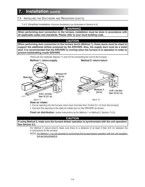
7. Installation (cont’d)7.4 INSTALLING THE DUCTWORK AND REGISTERS (CONT’D)7.4.3 Simplified installation (Volume Ventilation) (as illustrated in Section 6.3)! WARNINGWhen performing duct connection to the furnace, installation must be done in accordance withall applicable codes <strong>and</strong> st<strong>and</strong>ards. Please refer to your local building code.CAUTIONWhen performing duct connection to the furnace ducts (Method 1), these ducts must be sized tosupport the additional airflow produced by the ERV/HRV. Also, the supply duct must be a metalduct. It is recommended that the ERV/HRV is running when the furnace is in operation in order toprevent backdrafting inside ERV/HRV.There are two methods (figures 11 <strong>and</strong> 12) for connecting the unit to the furnace:Method 1: return-supplyMethod 2: return-returnMetal ductMinimum 18”(0.5 m)AABVD0171A+B = not lessthan 10’ (3.1 m)Bfigure 11figure 12Stale air intake:• Cut an opening into the furnace return duct (not less than 10 feet (3.1 m) from the furnace).• Connect this opening to the stale air intake port on the HRV/ERV as shown.VD0111Minimum 3’(0.9 m)A+B = not lessthan 10’ (3.1 m)Fresh air distribution: (same instructions as for Method 1 or Method 2, Section 7.4.2).CAUTIONIf using Method 2, make sure the furnace blower operation is synchronized with the unit operation!See Section 9.3.For Method 2 (return-return) make sure there is a distance of at least 3 feet (0.9 m) between the2 connections to the furnace.NOTE: For Method 1, it is not essential to synchronize the furnace blower operation with the unit operation,but we recommend it.14