part nos 45720 and 45725 - Venmar
part nos 45720 and 45725 - Venmar
part nos 45720 and 45725 - Venmar

You also want an ePaper? Increase the reach of your titles
YUMPU automatically turns print PDFs into web optimized ePapers that Google loves.
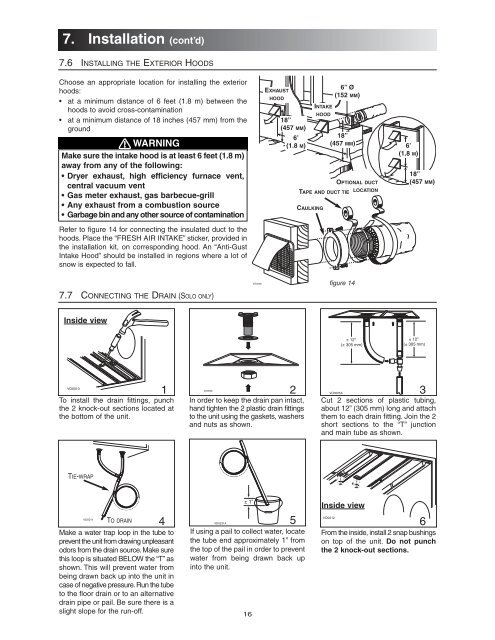
7. Installation (cont’d)7.6 INSTALLING THE EXTERIOR HOODSChoose an appropriate location for installing the exteriorhoods:• at a minimum distance of 6 feet (1.8 m) between thehoods to avoid cross-contamination• at a minimum distance of 18 inches (457 mm) from theground! WARNINGMake sure the intake hood is at least 6 feet (1.8 m)away from any of the following:• Dryer exhaust, high efficiency furnace vent,central vacuum vent• Gas meter exhaust, gas barbecue-grill• Any exhaust from a combustion source• Garbage bin <strong>and</strong> any other source of contaminationRefer to figure 14 for connecting the insulated duct to thehoods. Place the “FRESH AIR INTAKE” sticker, provided inthe installation kit, on corresponding hood. An “Anti-GustIntake Hood” should be installed in regions where a lot ofsnow is expected to fall.EXHAUSTHOOD18”(457 MM)OPTIONAL DUCTTAPE AND DUCT TIE LOCATIONCAULKINGINTAKEHOOD6” Ø(152 MM)6’18”(1.8 M) (457 MM)6’(1.8 M)18”(457 MM)7.7 CONNECTING THE DRAIN (SOLO ONLY)VD0028figure 14Inside view± 12"(± 305 mm)± 12"(± 305 mm)VO0010To install the drain fittings, punchthe 2 knock-out sections located atthe bottom of the unit.VO00081 2In order to keep the drain pan intact,h<strong>and</strong> tighten the 2 plastic drain fittingsto the unit using the gaskets, washers<strong>and</strong> nuts as shown.VO0005A3Cut 2 sections of plastic tubing,about 12” (305 mm) long <strong>and</strong> attachthem to each drain fitting. Join the 2short sections to the “T” junction<strong>and</strong> main tube as shown.TIE-WRAPVO0011TO DRAINMake a water trap loop in the tube toprevent the unit from drawing unpleasantodors from the drain source. Make surethis loop is situated BELOW the “T” asshown. This will prevent water frombeing drawn back up into the unit incase of negative pressure. Run the tubeto the floor drain or to an alternativedrain pipe or pail. Be sure there is aslight slope for the run-off.4 VD0231A± 1”If using a pail to collect water, locatethe tube end approximately 1” fromthe top of the pail in order to preventwater from being drawn back upinto the unit.16Inside viewVO00125 6From the inside, install 2 snap bushingson top of the unit. Do not punchthe 2 knock-out sections.