Page 10NOTE The light fixture may be replaced without removing water from the pool or spa.1. Turn off the main electrical switch or circuit breaker, as well as the switch, which operates theunderwater light.2. To remove the light assembly, remove the special pilot screw at top of the face ring, remove the lightassembly from the niche, and place the assembly on the deck.WARNINGBe sure to keep the special pilot screw from this underwater light. This screw mounts and electricallygrounds the housing securely to the mounting ring and wet niche. Failure to use the screw providedcould create an electrical hazard, which could result in death or serious injury to pool or spa users,installers or others due to electrical shock.3. Remove Junction Box cover, disconnect the light fixture wires and strain relief, and then pull the cordout of the conduit from the niche.4. Feed the new light fixture cord through the conduit from the niche to the Junction Box.NOTE Depending on the length of the conduit, special tools may be required to pull the cord through the conduit.5. Leave at least 4 feet of cord to coil around the light fixture; see Figure 1 (or Figure 2, for spa). Thisallows the light to be serviced after the pool or spa is filled with water.6. Cut the cord at the Junction Box, leaving at least 6 inches of cord to make connections.7. Strip 6 inches of the outer cord jacket from the cord to expose the three insulated wires. Be careful notto damage the insulation on the three inner wires.8. Install the strain relief over the cord jacket and connect all three wires to the corresponding circuitwires in the Junction Box, black wire to power, white wire to <strong>com</strong>mon, and green wire to ground.Install the Junction Box cover.9. Replace light assembly into the niche and tighten the special pilot screw.WARNINGUse only the special pilot screw provided with this underwater light. This screw mounts andelectrically grounds the housing securely to the mounting ring and wet niche. Failure to use the screwprovided could create an electrical hazard, which could result in death or serious injury to pool or spausers, installers or others due to electrical shock.10. Fill the pool or spa until the underwater light is <strong>com</strong>pletely submerged in water before operating thelight for more than 10 seconds. Turn on main switch or circuit breaker, as well as the switch, whichoperates the underwater light, to check for proper operation. Refer to Section 6, Operating Instructions.WARNINGNever operate this underwater light for more than 10 seconds unless it is totally submerged in water.Without total submersion, the light assembly will get extremely hot, which may result in seriousburns or in breakage of the bulb or lens. This may result in serious injury to pool or spa users,installers, or bystanders or in damage to property.
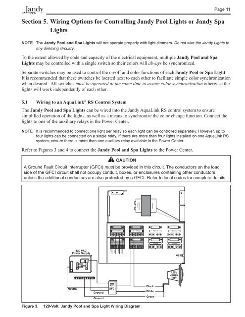
Page 11Section 5. Wiring Options for Controlling Jandy Pool Lights or Jandy SpaLightsNOTE The Jandy Pool and Spa Lights will not operate properly with light dimmers. Do not wire the Jandy Lights toany dimming circuitry.To the extent allowed by code and capacity of the electrical equipment, multiple Jandy Pool and SpaLights may be controlled with a single switch so their colors will always be synchronized.Separate switches may be used to control the on/off and color functions of each Jandy Pool or Spa Light.It is re<strong>com</strong>mended that these switches be located next to each other to facilitate simple color synchronizationwhen desired. All switches must be operated at the same time to assure color synchronization otherwise thelights will work independently of each other.5.1 Wiring to an AquaLink ® RS Control SystemThe Jandy Pool and Spa Lights can be wired into the Jandy AquaLink RS control system to ensuresimplified operation of the lights, as well as a means to synchronize the color change function. Connect thelights to one of the auxiliary relays in the Power Center.NOTE It is re<strong>com</strong>mended to connect one light per relay so each light can be controlled separately. However, up tofour lights can be connected on a single relay. If there are more than four lights installed on one AquaLink RSsystem, ensure there is more than one auxiliary relay available in the Power Center.Refer to Figures 3 and 4 to connect the Jandy Pool and Spa Lights to the Power Center.CAUTIONA Ground Fault Circuit Interrupter (GFCI) must be provided in this circuit. The conductors on the loadside of the GFCI circuit shall not occupy conduit, boxes, or enclosures containing other conductorsunless the additional conductors are also protected by a GFCI. Refer to local codes for <strong>com</strong>plete details.120 VACPower Supply120VJandyLightNeutralGroundGroundGFCIBlackWhiteGreenFigure 3.120-Volt Jandy Pool and Spa Light Wiring Diagram