P - Transmission
P - Transmission
P - Transmission

Create successful ePaper yourself
Turn your PDF publications into a flip-book with our unique Google optimized e-Paper software.
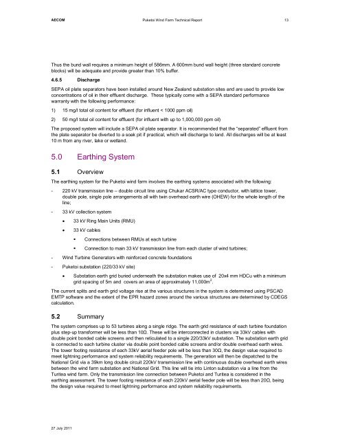
AECOMPuketoi Wind Farm Technical Report13Thus the bund wall requires a minimum height of 586mm. A 600mm bund wall height (three standard concreteblocks) will be adequate and provide greater than 10% buffer.4.6.5 DischargeSEPA oil plate separators have been installed around New Zealand substation sites and are used to provide lowconcentrations of oil in their effluent discharge. These typically come with a SEPA standard performancewarranty with the following performance:1) 15 mg/l total oil content for effluent (for influent < 1000 ppm oil)2) 50 mg/l total oil content for effluent (for influent with up to 1,000,000 ppm oil)The proposed system will include a SEPA oil plate separator. It is recommended that the “separated” effluent fromthe plate separator be diverted to a soak pit if practical, which will discharge to land. All discharges will be at least10 m from any river, lake or wetland.5.0 Earthing System5.1 OverviewThe earthing system for the Puketoi wind farm involves the earthing systems associated with the following:- 220 kV transmission line – double circuit line using Chukar ACSR/AC type conductor, with lattice tower,double pole, single pole arrangements all with twin overhead earth wire (OHEW) for the whole length of theline;- 33 kV collection system33 kV Ring Main Units (RMU)33 kV cables• Connections between RMUs at each turbine• Connection to main 33 kV transmission line from each cluster of wind turbines;- Wind Turbine Generators with reinforced concrete foundations- Puketoi substation (220/33 kV site)Substation earth grid buried underneath the substation makes use of 20x4 mm HDCu with a minimumgrid spacing of 5m and covers an area of approximately 11,000m 2 .The current splits and earth grid voltage rise at the various structures in the system is determined using PSCADEMTP software and the extent of the EPR hazard zones around the various structures are determined by CDEGScalculation.5.2 SummaryThe system comprises up to 53 turbines along a single ridge. The earth grid resistance of each turbine foundationplus step-up transformer will be less than 10. These will be interconnected in clusters via 33kV cables withdouble point bonded cable screens and then reticulated to a single 220/33kV substation. The substation earth gridis connected to each turbine cluster via double point bonded cable screens and/or double overhead earth wires.The tower footing resistance of each 33kV aerial feeder pole will be less than 30, the design value required tomeet lightning performance and system reliability requirements. The generation will then be dispatched to theNational Grid via a 39km long double circuit 220kV transmission line with continuous double overhead earth wiresbetween the wind farm substation and National Grid. This line will tie into Linton substation via a line from theTuritea wind farm. Only the transmission line connection between Puketoi and Turitea is considered in theearthing assessment. The tower footing resistance of each 220kV aerial feeder pole will be less than 20, beingthe design value required to meet lightning performance and system reliability requirements.27 July 2011