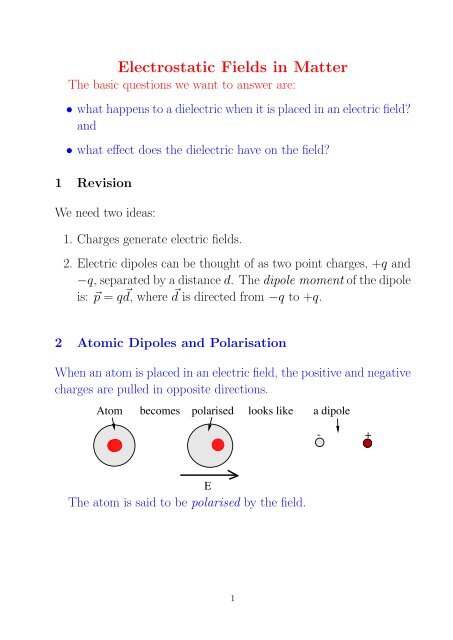
Electrostatic Fields in Matter
Electrostatic Fields in Matter
Electrostatic Fields in Matter

You also want an ePaper? Increase the reach of your titles
YUMPU automatically turns print PDFs into web optimized ePapers that Google loves.
3 Polarisation MechanismsThere are 3 mechanisms <strong>in</strong>volved <strong>in</strong> the polarisation of atoms andmolecules:1. Electronic polarization - displacement of electrons from their normalposition <strong>in</strong> molecules.2. Ionic polarization (or atomic polarization) - the displacement ofions from their normal positions with<strong>in</strong> molecules.3. Dipolar polarization - alignment of permanent molecular dipolesby the field.The size of the effect is largest for 3, then 2 then 1. However effects3 and 2 are not always present.4 Frequency Dependence (non-exam<strong>in</strong>able)The polarisation generated by an alternat<strong>in</strong>g field varies with frequencyand temperature.• Dipole polarisation occurs only at relatively low frequencies (upto high radio frequencies) and disappears at low temperatures.• Atomic polarisation extends to the <strong>in</strong>frared.• Electronic polarisation occurs for virtually all frequencies.The refractive <strong>in</strong>dex is due to electronic polarisation.3
5 Parallel Plate Capacitor.A parallel plate capacitor is a useful model for demonstrat<strong>in</strong>g someof the basic ideas about dielectrics.The figure shows two parallel conduct<strong>in</strong>g plates. A charge Q hasbeen transferred from the bottom plate to the top and the plates arenow isolated.+QAdE-QVFrom Gauss’s law ⃗ E = σ ɛ 0= Q/Aɛ 0(5)V =∫⃗E · ⃗ds = Ed (6)C = Q V = ɛ 0Ad(7)These equations are based on the assumption that the field betweenthe plates is constant, which is reasonable if the plates areclose together.What happens when a dielectric is placed between the plates?The orig<strong>in</strong>al field, produced by the charges on the plates, pushesthe +ve charges <strong>in</strong> the dielectric down and -ve charges up. Thedielectric becomes polarised.4
This leaves a layer of negative charge on the top surface of thedielectric and a positive layer at the bottom.The orig<strong>in</strong>al charge Q, which was placed on the capacitor plates,is referred to as free charge.The charge <strong>in</strong>duced on the dielectric surface is called bound charge.The bound charge generates a new field, <strong>in</strong> the opposite directionto the orig<strong>in</strong>al field. This new field is called the depolarisation field.The total field <strong>in</strong> the dielectric is the sum of the orig<strong>in</strong>al field (fromthe free charges) and the depolarisation field - it will be smaller thanthe orig<strong>in</strong>al field.Bound chargesFree chargesDepolarisation fieldOrig<strong>in</strong>al fieldLook<strong>in</strong>g at equations (6) and (7), we see that when a dielectricis placed between charged plates which are not connected, then Qrema<strong>in</strong>s constant while V decreases; hence C <strong>in</strong>creases. The factorby which C <strong>in</strong>creases is called the dielectric constant K (or therelative permittivity, ɛ r ).-5
6 Bound Charges• Detailed derivation: Griffiths section 4.2.1, page 166 (non-exam<strong>in</strong>able)• Simpler derivation: Griffiths section 4.2.2, page 170.The follow<strong>in</strong>g is similar to Griffith’s simpler derivation.When a dielectric is polarised, the movement of charge createsregions <strong>in</strong> the dielectric which can have a net charge. We will deriveexpressions for the densities of these bound charges.The electric field produced by a polarised dielectric is calculatedsimply by calculat<strong>in</strong>g the field due to the bound charges.6.1 Surface Bound Charge DensityThe diagram shows a small area da at the surface of a polariseddielectric. This area is represented by a vector da, ⃗ normal to thesurface. The polarisation at this po<strong>in</strong>t is at some angle θ to thesurface normal.In each atom the positive charges have been displaced by d ⃗ relativeto the negative, so ⃗p = Qd ⃗ (and remember P ⃗ = n⃗p).PθdatThe charges move <strong>in</strong> the direction of ⃗ P . At the surface this leavesa layer of uncompensated charge, with a thickness t = d cos θ.6
The amount of charge <strong>in</strong> the element <strong>in</strong> the diagram is the productof the element’s volume and the charge per unit volume:i.e. the charge is: (da×t)×(nQ) = nQd cos θda = n⃗p· ⃗da = ⃗ P · ⃗da(8)The surface charge density (i.e. the charge per unit area) is thus:σ b = ⃗ P · ˆn (9)where ˆn is a unit vector, perpendicular to the surface and po<strong>in</strong>t<strong>in</strong>gout of the surface.6.2 Volume Bound Charge DensityWe saw above, that the net charge flow<strong>in</strong>g across a surface when adielectric is polarised is P ⃗ · ⃗da. If the volume is enclosed by a surface,then the net charge which flows out of that volume is given by :∮Q out = ⃗P · ⃗da (10)areaThe charge left beh<strong>in</strong>d <strong>in</strong> the volume is just −Q out .∮∮−Q out = − ⃗P · ⃗da = − ∇ · ⃗P dτ (11)areaThe last step uses Gauss’ theorem.What this tells us is that the net charge density <strong>in</strong>side the volumeelement is :volρ b = −∇ · ⃗P (12)Note that s<strong>in</strong>ce the volume charge density depends on spatialderivatives of the polarisation, it will be zero <strong>in</strong>side a uniformly polariseddielectric.7
7 Permittivity and SusceptibilityThe permittivity (and dielectric constant) are related to the susceptibility.For simplicity we consider the case of a constant field, as foundbetween parallel plates. We can then omit the vector nature of thefield.From Gauss’s lawUs<strong>in</strong>g (9) and (4):E = σ f − Pɛ 0E = σ f − σ bɛ 0(13)= σ f − ɛ 0 χ e Eɛ 0giv<strong>in</strong>g E = σ fɛ 011 + χ e(14)The field is reduced by the factor χ e + 1. The capacitance is<strong>in</strong>creased by the same factor. Keep<strong>in</strong>g <strong>in</strong> m<strong>in</strong>d the def<strong>in</strong>ition of thedielectric constant, we have:K = ɛ r = χ e + 1 (15)The permittivity of a dielectric is : ɛ = ɛ r ɛ 0Equation (14) could be written <strong>in</strong> a variety of ways:E =σ fɛ 0 (1 + χ e ) = σ f= σ fɛ r ɛ 0 ɛ(16)Equation (16) illustrates an important po<strong>in</strong>t. In dielectrics it isusually possible to use the normal equations for calulat<strong>in</strong>g electricfields due to free charges by replac<strong>in</strong>g ɛ 0 by ɛ.8
This could all get confus<strong>in</strong>g!Remember• ɛ will be a very small number (s<strong>in</strong>ce ɛ 0 = 8.84 × 10 −12 ).• Relative permittivity and dielectric constant are the same th<strong>in</strong>g,with values usually between 1 and 100 (although 50,000 is possible).• χ e is one less than ɛ r . (So what is its value for free space?).8 Electric DisplacementThe differential form of Gauss’s law is:∇ · ⃗E = ρ ɛ 0(17)We now th<strong>in</strong>k of the charge as two parts: ρ = ρ f + ρ b .This means that ∇ · ⃗E = ρ f + ρ bɛ 0= ρ f − ∇ · ⃗Pɛ 0and this gives us ∇ · (ɛ 0⃗ E + ⃗ P ) = ρf (18)We now def<strong>in</strong>e a new quantity, the electric displacement vector⃗D, def<strong>in</strong>ed as⃗D = ɛ 0⃗ E + ⃗ P (19)(This also means that ⃗ D = ɛ ⃗ E) (20)We then have ∇ · ⃗D = ρ f (21)We can th<strong>in</strong>k of equation (21) as Gauss’s law <strong>in</strong> a dielectric.9
¨¨© ©© ©¨⃗D is convenient because it depends only on the free charge. Youcan calculate ⃗ D <strong>in</strong> the same way as you calculate ⃗ E, except thatyou only need <strong>in</strong>clude the free charge and there will be an ɛ 0 miss<strong>in</strong>gsomewhere.The <strong>in</strong>tegral form of equation (21) would be:∮⃗D · ⃗da = Q fenc (22)In a dielectric then, we have two equations:∇ · ⃗D = ρ f and ∇ × ⃗ E = 0 (23)ExampleA parallel plate capacitor with plates 5 mm apart is filled withpolythene, which has ɛ r = 2.26. The capacitor is connected to a 9 Vbattery.1. Calculate ⃗ E, ⃗ P , σ b , ⃗ D and σ f <strong>in</strong> the dielectric.2. Calculate the field due to the free charge and the depolaris<strong>in</strong>gfield.3. What extra <strong>in</strong>formation would you need if you wished to calculate⃗p, the atomic dipole moment?¢ ¢ £ £ £ ¢¡ ¡ ¡ ¡ ¡ ¡ ¡ ¡ ¡ ¡ ¡ ¡ ¡ ¡ ¡ ¡ ¡E P D¤ ¤ ¤ ¤ ¤ ¤ ¤ ¤ ¤ ¤ ¤ ¤ ¤ ¤ ¤ ¤¥ ¥ ¥ ¥ ¥ ¥ ¥ ¥ ¥ ¥ ¥ ¥ ¥ ¥ ¥ ¥ ¥¤¤ ¤ ¤ ¤ ¤ ¤ ¤ ¤ ¤ ¤ ¤ ¤ ¤ ¤ ¤ ¤¥ ¥ ¥ ¥ ¥ ¥ ¥ ¥ ¥ ¥ ¥ ¥ ¥ ¥ ¥ ¥ ¥¤¦ ¦ ¦ § § § § ¦10
SolutionS<strong>in</strong>ce <strong>in</strong> this simple geometry, all the vector quantities are <strong>in</strong> thesame direction, we will ignore their vector nature.1.E = V d =P = ɛ 0 (K − 1)E9 V5 mm = 1.8 × 10³ Vm −1= 8.85 × 10 −12 (2.26 − 1)1.8 × 10 3= 2.01 × 10 −8 Cm −2σ b = P = 2.01 × 10 −8 Cm −2D = ɛ 0 E + P= 8.85 × 10 −12 × 1.8 × 10 3 + 2.01 × 10 −8= 3.60 × 10 −8 Cm −2σ f = D = 3.60 × 10 −8 Cm −211
2. For a sheet of charge, with charge per unit area of σ, Gauss’slaw gives the field as σ/ɛ 0 .So E free = σ fɛ 0= 4.07 × 10 3 Vm −1and E bound = σ bɛ 0= 2.27 × 10 3 Vm −13. The polarisation ⃗ P is def<strong>in</strong>ed as the total dipole moment per unitvolume. In order to calculate ⃗p, the moment of an <strong>in</strong>dividualdipole, we would need to know the number of dipoles per unitvolume.12
9 Boundary Conditions.What happens at the junction of two dielectrics?In the figure, the dielectric above the horizontal l<strong>in</strong>e has permittivityɛ 1 , while below the l<strong>in</strong>e it is ɛ 2 .ε1ε2Dn1Dn2Et1Et2Take the Gaussian pill-box on the left <strong>in</strong> the figure and imag<strong>in</strong>eits height goes to zero. If there is no free charge at the boundary,there is no net flux of ⃗ D out of the pill-box. Hence the boundarycondition for ⃗ D is:D n1 = D n2 (24)We also know that the l<strong>in</strong>e <strong>in</strong>tegral of the electric field aroundthe rectangle on the right must be zero (s<strong>in</strong>ce ∇ × ⃗ E = 0). As weimag<strong>in</strong>e the rectangle shr<strong>in</strong>k<strong>in</strong>g to an <strong>in</strong>f<strong>in</strong>itesimal size, we see that:E t1 = E t2 (25)i.e. across the boundary of 2 dielectrics, the normal component of⃗D is cont<strong>in</strong>uous and the tangential component of ⃗ E is cont<strong>in</strong>uous.13
10 Force on a DielectricIn general, an electric field will exert a torque on a dipole which isnot parallel to the field and a force on a dipole if the two centres ofcharge are at po<strong>in</strong>ts where the field is different.We will not look at this <strong>in</strong> detail, although it is covered <strong>in</strong> Griffiths.However there is an <strong>in</strong>terest<strong>in</strong>g example, which shows how lateralth<strong>in</strong>k<strong>in</strong>g can sometimes get answers out of apparently difficultsituations.Consider the situation shown below.Lx+QA parallel plate capacitor with a slab of dielectric partly <strong>in</strong>sertedbetween the plates. The plates are isolated, so Q, the free charge onthe plates, is constant.Our task is to calculate the force on the dielectric slab. The situationis complex. The field is not constant and hence the polarisationwill also vary with position.The method used is to consider the energy. If the slab moves adistance dx <strong>in</strong>to the capacitor, the energy changes s<strong>in</strong>ce the capacitancechanges. From conservation of energy we know that the workdone by the force mov<strong>in</strong>g the dielectric must be equal to the change<strong>in</strong> the stored energy.( 1 Q 2 ) (i.e. F dx = ∆ = − 1 Q 2 )dC =(− 1 )2 C 2 C 2 2 V 2 dC (26)14-Q
Take the length of the plates to be L and the distance the dielectric<strong>in</strong>trudes <strong>in</strong>to the space between the plates to be x. The totalcapacitance is thus:C = ɛ 0A L − xd L+ Kɛ 0A xd L = ɛ 0Ad+ ɛ 0A (K − 1)xd LIf x changes by dx, then the change <strong>in</strong> C will be:(27)dC = ɛ 0A (K − 1)dx (28)d LComb<strong>in</strong><strong>in</strong>g equations (26), (27) and (28) gives f<strong>in</strong>ally:F = − 1 2 V 2ɛ 0A (K − 1)(29)d LThe expression itself is not particularly important. The <strong>in</strong>terest<strong>in</strong>gpo<strong>in</strong>t is that it is possible to calculate the force <strong>in</strong> a complex situation<strong>in</strong> such a simple way.15
11 Energy <strong>in</strong> a Dielectric.The follow<strong>in</strong>g represents a simple derivation, although the result obta<strong>in</strong>edis quite general.We know that the energy stored <strong>in</strong> a charged capacitor isW = 1 2 CV 2 (30)For a parallel plate capacitor C = Kɛ o A/d and V = Ed.Thus W = 1 2 Kɛ oAdE 2 (31)The energy per unit volume stored <strong>in</strong> the capacitor is thus:U = 1 2 Kɛ 0E 2 = 1 2 ɛE2 = 1 2 ⃗ D · ⃗E (32)The energy stored <strong>in</strong> a dielectric, for a given field, is K times largerthen the energy stored <strong>in</strong> a vacuum. The extra energy comes fromthe polarization of the dielectric.16
12 SummaryThe state of a dielectric is characterised by three vector quantities:The electric field ⃗ EThe polarisation ⃗ P (= total dipole moment per unit volume).The displacement ⃗ D def<strong>in</strong>ed by ⃗ D = ɛ 0⃗ E + ⃗ P .There are relations between these quantities.⃗D = ɛ ⃗ E = ɛ r ɛ 0⃗ E and ⃗ P = ɛ0 χ e⃗ EThe polarisation gives rise to bound charges:σ b = ⃗ P · ˆn and ρ b = −∇ · ⃗PThe displacement D ⃗ is determ<strong>in</strong>ed by the free charges.∮∇ · ⃗D = ρ f (<strong>in</strong> <strong>in</strong>tegral form this is ⃗D · ⃗da = Q fenc )The field E ⃗ is determ<strong>in</strong>ed by ALL the charges (i.e.bound)free plusAt a dielectric boundary the normal component of ⃗ D and thetangential component of ⃗ E are cont<strong>in</strong>uous.The energy density <strong>in</strong> a polarised dielectric is 1 2 ⃗ D · ⃗E.17
ExampleA hollow dielectric sphere, with <strong>in</strong>ner radius R 1 and outer radiusR 2 has susceptibility χ e . A charge Q is spread uniformly over the<strong>in</strong>ner surface of the sphere’1. F<strong>in</strong>d ⃗ D, ⃗ E and ⃗ P <strong>in</strong> the three regions r < R1 , R 1 ≤ r ≤ R 2and r > R 2 .2. Calculate the bound charges.++++ ++++ + + 18+++R+ + ++1R+++2+++